background image

CUSTOMER

SUPPORT

INFORMATION

Order 

toll-free

in the U.S.: Call 

877-877-BBOX

(outside U.S. call 

724-746-5500

)

FREE technical support 24 hours a day, 7 days a week: Call 

724-746-5500

or fax 

724-746-0746

Mailing address: 

Black Box Corporation

, 1000 Park Drive, Lawrence, PA 15055-1018

Web site: 

www.blackbox.com

•   E-mail: 

info@blackbox.com

MAY 1997

IC714A-449-R2

IC714AE-449-R2

IC714A-48-449-R2

IC714A-530-R2

IC714AE-530-R2

IC714A-48-530-R2

IC714A-V35-R2

IC714AE-V35-R2

IC714A-48-V35-R2

IC714A-X21-R2

IC714AE-X21-R2

IC714A-48-X21-R2

G.703 Codirectional Converter

G.703

V.35 CODIRECTIONAL

PWR

TD

RD

LOS

TEST

ERR

PATT

REM

ANA

DIG

Summary of Contents for IC714A-449-R2

Page 1: ...dress Black Box Corporation 1000 Park Drive Lawrence PA 15055 1018 Web site www blackbox com E mail info blackbox com MAY 1997 IC714A 449 R2 IC714AE 449 R2 IC714A 48 449 R2 IC714A 530 R2 IC714AE 530 R2 IC714A 48 530 R2 IC714A V35 R2 IC714AE V35 R2 IC714A 48 V35 R2 IC714A X21 R2 IC714AE X21 R2 IC714A 48 X21 R2 G 703 Codirectional Converter G 703 V 35 CODIRECTIONAL PWR TD RD LOS TEST ERR PATT REM AN...

Page 2: ...ent is operated in a commercial environment Operation of this equipment in a residential area is likely to cause interference in which case the user at his own expense will be required to take whatever measures may be necessary to correct the interference Changes or modifications not expressly approved by the party responsible for compliance could void the user s authority to operate the equipment...

Page 3: ... El aparato eléctrico debe ser montado a la pared o al techo sólo como sea recomendado por el fabricante 8 Servicio El usuario no debe intentar dar servicio al equipo eléctrico más allá a lo descrito en las instrucciones de operación Todo otro servicio deberá ser referido a personal de servicio calificado 9 El aparato eléctrico debe ser situado de tal manera que su posición no interfiera su uso La...

Page 4: ...r una antena externa deberá ser localizada lejos de las lineas de energia 16 El cable de corriente deberá ser desconectado del cuando el equipo no sea usado por un largo periodo de tiempo 17 Cuidado debe ser tomado de tal manera que objectos liquidos no sean derramados sobre la cubierta u orificios de ventilación 18 Servicio por personal calificado deberá ser provisto cuando A El cable de poder o ...

Page 5: ... this publication and make changes without obligation to notify any person of such revisions and changes The manufacturer shall not be liable for any direct indirect special incidental or consequential damages whether based on contract tort or any legal theory SAFETY WARNING Always observe standard safety precautions while installing operating or troubleshooting this product To avoid the possibili...

Page 6: ...ng 17 2 2 4 G 703 Codirectional Rules 17 2 3 Rate Conversion Rules 19 2 4 Physical Description 19 3 Installation 20 3 1 Unpacking 20 3 2 Site Requirements 20 3 3 Setting Jumpers 21 3 3 1 Overview 21 3 3 2 The Jumper Setting Procedure 23 3 4 Installation in 19 Inch Racks 23 3 4 1 Overview 23 3 4 2 Installing a Single Unit in a 19 Inch Rack 24 3 4 3 Installing Two Units in a 19 Inch Rack 25 3 5 Conn...

Page 7: ...ating Instructions 33 4 2 1 Turn On Procedure 33 4 2 2 Activating Loops 33 4 2 3 Turn Off Procedure 33 4 3 Diagnostic Loops 33 4 3 1 The Modem Self Test 34 4 3 2 Local Analog Loopback 35 4 3 3 Remote Digital Loopback 36 4 3 4 Local Digital Loopback 37 4 4 Calling Black Box 38 4 5 Shipping and Packaging 39 Appendix Pinouts 42 ...

Page 8: ...ss Less than 20 dB up to 128 kHz Less than 14 dB up to 384 kHz Pulse Amplitude 1 0 V nominal Zero Amplitude 0 V 0 1 V max Clock Frequency 64 kHz Frequency Tracking 500 ppm Connector 5 screw terminal block Jitter Performance To G 823 requirements 1 2 Data Communications Interface Type Models with 449 affix EIA RS 530 adapted to EIA RS 449 ITU TSS V 11 V 36 EIA RS 422 423 Models with 530 affix EIA R...

Page 9: ...ntain required violations DCD 48 or 56 kbps When the Rx pair contains the required violations the DCD signal reflects the state of the remote RTS DCD is always OFF when no violations are detected CTS output ON after RTS ON with delay OFF when RTS OFF or during Loss of Signal condition DSR output ON V when power is available Clock Source From G 703 Receive pair LBT from DCE EXT or from internal sou...

Page 10: ...l solder contact to connect grounds Loopback tests can also be triggered by interface signals from local DTE Diagnostics Local digital loopback local analog loopback V 54 Loop 3 remote digital loopback V 54 Loop 2 511 bit V 52 BERT all user initiated and user terminated Indicators 6 Front mounted LEDs Power PWR Receive Data RD Transmit Data TD Loss of Signal LOS Test TEST and Error ERR Power IC714...

Page 11: ...ansformer primary and frame ground also 1500 VAC betwen AC mains transformer primary and each of these data communication interface and frame ground NOTE This measurement was derived by testing for one minute Maximum Altitude 8000 ft 2348 4 m Temperature Tolerance 32 to 122 F 0 to 50 C Humidity Tolerance Up to 95 noncondensing Enclosure High impact plastic Size 1 8 H x 7 6 W x 9 6 D 4 6 x 19 3 x 2...

Page 12: ... to a 37 pin D subminiature DB37 female interface connector Models whose product codes include 530 support the EIA RS 530 physical electrical interface with ITU TSS V 11 compatible signal levels they have a 25 pin D subminiature DB25 female interface connector Models whose product codes include V35 support the ITU TSS V 35 physical electrical interface they have a 34 pin M block M 34 female interf...

Page 13: ... end Async devices Transmit Data to Converters RTS and Receive Data to CTS As a 1200 bps asynchronous secondary channel for connecting additional DTE units over the same link You can use the Converter s front panel LEDs to continuously monitor the main channel s activity and synchronization The Converter provides V 54 diagnostic capabilities with local digital and analog and remote digital loopbac...

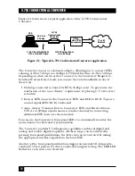
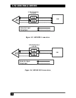
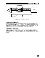
Page 14: ...eive Timing Used for G 703 Transmit Timing When G 703 receive timing is used for G 703 transmit timing three timing options for the data communication side associated with the loopback timing LBT on the G 703 side are available Receive Clock and Transmit Clock are both outputs from the Converter which serves as a DCE see Figure 2 3 on the next page X 21 interface only Receive Clock and Transmit Cl...

Page 15: ...onnection Figure 2 4 LBT DCE21 Connection Information Signal Timing Signal Information Signal Timing Signal G 703 Codirectional Converter Elastic Buffer Elastic Buffer DCE PCM Equip Elastic Buffer Elastic Buffer G 703 Codirectional Converter DCE PCM Equip ...

Page 16: ...ceive and the transmit directions of transmission Figure 2 6 on the next page shows this timing mode Internal Clock Timing Mode The Converter s internal oscillator is usually used as the source for G 703 transmit timing for testing purposes only but can also be used with systems that do not have a clock source Figure 2 7 on the next page shows this timing mode Information Signal Timing Signal Elas...

Page 17: ...e Figure 2 7 Internal Clock Timing Mode Information Signal Timing Signal Information Signal Timing Signal DCE G 703 Codirectional Converter PCM Equip Elastic Buffer Elastic Buffer G 703 Codirectional Converter DTE or DCE PCM Equip Elastic Buffer Elastic Buffer Oscillator ...

Page 18: ...03 codirectional signals in each direction of transmission are coded as follows The composite timing data signal conveys the 64 KHz bit timing information the 8 KHz octet information by introducing violations into the signal and the 64 kbps data pattern A binary one 64 kbps bit period is coded as a block of the four bits 1100 A binary zero 64 kbps bit period is coded as a block of the four bits 10...

Page 19: ... 703 Code Conversion 6 7 8 1 2 3 4 5 6 7 8 1 0 0 0 1 1 0 1 0 1 1 1 0 G 703 Codirectional Converter G 703 Line Tail End Circuit TC TD RD RC TD EXTC EXTC RD RC Modem V 35 V 36 RS 530 Modem Line Side of Office Terminal Bit Number 64 kbps data Binary Data Three Level Data Violated Data ...

Page 20: ...nc channel North American T1 1 544 Mbps applications require that this bit position be set to a binary 1 You can do this easily by leaving the RTS pin open not connected 48 to 64 kbps conversion is performed by suppressing bit positions number 7 and 8 The suppressed bits are used in the same way as those suppressed for 56 to 64 kbps conversion 2 4 Physical Description The G 703 Codirectional Conve...

Page 21: ... rack 3 1 Unpacking Unpack the equipment this way Carefully take the G 703 Codirectional Converter out of the box it came in and place the Converter on a clean surface Inspect the unit for damage Immediately report any damage you find to your carrier and to Black Box 3 2 Site Requirements An AC powered G 703 Codirectional Converter should be installed within 5 feet 1 5 m of a grounded AC outlet ca...

Page 22: ...d For example the JP1 jumper is in fact partially obscured by the interface module in the AC powered models Also in both AC and DC powered models the JP1 label is partially or completely covered by material that helps secure the board to the rear panel There is also a second element labeled JP1 on the interface module itself Just like the other JP1 this element will also serve to connect chassis g...

Page 23: ...rom the RS 422 V 35 external source INT The Tx pair and transmit timing are from the internal source LBT DTE DTE Connection to DTE with transmit and receive timing derived from the unit s recovered clock DCE Connection to DCE while both the DCE and the unit operate with external transmit timing DCE 21 Connection to X 21 DCE The unit s transmit and receive timing are derived from the DCE BAUD 64 64...

Page 24: ... This releases the unit s drawer mechanism now you can pull the screws as if they were the knobs on a drawer and expose or remove the unit s circuit board Identify the jumpers s refer to Figure 3 1 on page 21 Move the jumper s to your desired position s Replace the circuit board and screw the rear panel screws back in 3 4 Installation in 19 inch Racks 3 4 1 OVERVIEW The G 703 Codirectional Convert...

Page 25: ...re the Converter for rack installation attach the two brackets to the sides of the unit Do this by inserting screws and flat washers into the two holes at the front of each side of the Converter nuts are already in place inside the unit After attaching the brackets install the unit in your 19 inch rack by fastening the brackets to the rack s side rails with four screws not included in the kit two ...

Page 26: ...er unit using the four included screws and flat washers The rails must be attached so that they oppose each other The narrow flange of the first rail must face the wide flange of the second rail 2 Using four included screws and flatwashers for each bracket attach the two short brackets to the vacant sides of the Converters 3 Slide the two Converters side rails into each other fastening the two uni...

Page 27: ...26 G 703 CODIRECTIONAL CONVERTER Figure 3 3 Installing two units in a 19 inch rack ...

Page 28: ...d control signals between the Converter and the DCE for more detailed information refer to the Appendix The terminal block has five screws for connecting transmit and receive ITU TSS CCITT G 703 lines the transmit pair where XMT is indicated for data output from the unit the receive pair where RCV is indicated for data input to the unit and chassis ground where GND is indicated Connect power and d...

Page 29: ...re that you replace it only with a fuse rated for the required amount of current You must avoid using repaired fuses or short circuiting the fuse holders The fuse and one replacement fuse are located in the top part of the mains connector on the Converter s rear panel The nominal current value of the fuse is 0 125 A for 230 VAC operation or 0 25 A for 115 VAC operation Whenever it is likely that t...

Page 30: ...V The unit is auto detecting and non polarity sensitive XMT line equipment to RCV Converter XMT line equipment to RCV Converter RCV line equipment to XMT Converter RCV line equipment to XMT Converter Optional Ground line equipment to ground Converter the rightmost terminal Figure 3 6 Wire insertion details XMT RCV GND 1 Insert screwdriver into square hole 2 Raise inserted screwdriver putting press...

Page 31: ...o a standard DB37 female The pinouts of these connectors of the RS 530 to RS 449 adapter cable and of cables you can run to DTE and DCEs are listed in the Appendix To connect the Converter to a DTE or DCE use an appropriate cable that is pinned correctly straight through for DTE crossed for DCE consult the Appendix Run this cable from the other device to the Converter and attach it to the Converte...

Page 32: ...you what to do if there is a problem with the unit 4 1 Front Panel Controls and LEDs Six LEDs are visible through the front panel see Figure 4 1 below Each LED s function is described in Table 4 1 on the next page Four pushbuttons are available for activating diagnostic tests as described in Table 4 1 Figure 4 1 Front panel of the G 703 Codirectional Converter PWR DIG ANA REM PATT TD RD LOS TEST E...

Page 33: ...t at receive Receive Data output and goes off when a steady mark is present LOS Red LED Lights when the RX pair does not contain Loss of Signal the violations required TEST Red LED Lights when a loopback is performed Test ERR Red LED Lights when errors are detected in the test pattern Active only after PATT button is pressed DIG Pushbutton Activates local digital loopback ANA Pushbutton Activates ...

Page 34: ...2 3 TURN OFF PROCEDURE The Converter can be turned off only by disconnecting its power NOTE Always disconnect the power cord from the AC outlet before you disconnect it from the Converter 4 3 Diagnostics The G 703 Codirectional Converter provides local loopback and remote digital loopback in compliance with the V 54 standard These loopbacks can be activated manually from the unit s front panel On ...

Page 35: ... functionally disconnected 4 3 1 THE MODEM SELF TEST To verify that the G 703 Codirectional Converter itself is operating correctly initiate the modem self test by depressing the PATT and ANA buttons refer to Figure 4 3 on the next page 1 Press ANA to start local analog loopback The TEST LED should light 2 Press PATT to begin test pattern transmission Verify that the TEST LED is still lit and that...

Page 36: ... the V 36 RS 449 models This test checks the performance of the local Converter s modem the local DTE and the connections between them Perform this test separately at the local and remote sites refer to Figure 4 4 below 1 Press ANA or raise Local Loopback to start local analog loopback The TEST LED should light The Converter s G 703 transmit output should be connected to its own receiver Figure 4 ...

Page 37: ...PBACK Activate the remote digital loopback test by depressing the REM button or by raising the level of the Remote Loopback signal received by the Converter s DTE side connector on DB25 Pin 21 on the RS 530 models M 34 Pin HH on the V 35 models or DB37 Pin 14 on the V 36 RS 449 models This test involves creating an outbound loopback at the remote Converter see Figure 4 5 on the next page The test ...

Page 38: ...or had initiated a remote digital loopback at the remote site With this test the remote operator can check the performance of the remote and local Converters and the lines between them 1 Press DIG the local Converter will signal the remote unit and will start local digital loopback The TEST LED should light on both units The local Converter s G 703 receive input should be connected to its own tran...

Page 39: ... is malfunctioning do not attempt to alter or repair the unit It contains no user serviceable parts Contact Black Box Technical Support at 724 746 5500 the problem might be solvable over the phone Before you do make a record of the history of the problem We will be able to provide more efficient and accurate assistance if you have a complete description including the nature and duration of the pro...

Page 40: ...efully We recommend that you use the original container If you are shipping the Converter for repair make sure you include its power cord and for V 36 RS 449 models the adapter cable you re using with it If you are returning the Converter make sure you include its manual as well Before you ship contact Black Box to get a Return Authorization RA number ...

Page 41: ...Pin RS 449 Pin Pin s 101 A 1 1 1 102 B 7 19 20 8 37 103 P 2 4 2 S 14 22 9 104 R 3 6 4 T 16 24 11 105 C 4 7 3 19 25 10 Table A 1 Interface Connector Pinouts Description Chassis ground Can be isolated from Signal Ground or tied to it Common ground for signaling and for the DC power supply Can be isolated from Shield or tied to it Serial digital data from the DTE The data transitions must occur on th...

Page 42: ... is lost or DSRgoes low An serial data rate clock input to the Converter from a data source Positive clock transitions must correspond to data transitions A serial data rate clock output from the Converter to a data source Positive clock transitions correspond to data transitions Signal Names Clear to Send CTS CS Data Set Ready DSR DCE Ready DCER Data Mode DM Received Line Signal Detector RLSD Rec...

Page 43: ... transitions correspond to data transitions The DTE can raise this signal to the Converter to force it into local analog loopback see Section 4 3 2 The DTE can raise this signal to the Converter to force it into remote digital loopback see Section 4 3 3 The Converter raises this signal to the DTE during any test mode Signal Names Serial Clock Rcv SCR Rcv Tim ing RT Rec ver Signal Element Timing DC...

Page 44: ...r DCE M 34 C RTS D CTS E DSR F DCD P TRANSMITTED DATA A S TRANSMITTED DATA B R RECEIVED DATA A T RECEIVED DATA B Y TRANSMITTER TIMING A AA TRANSMITTER TIMING B V RECEIVER TIMING A X RECEIVER TIMING B A PROTECTIVE GND B SIGNAL GND HH REMOTE LOOPBACK JJ LOCAL LOOPBACK KK TEST MODE C D E F P S R T Y AA V X A B HH JJ KK ...

Page 45: ...4 G 703 Codirectional Converter DCE M 34 C RTS F DCD P TRANSMITTED DATA A S TRANSMITTED DATA B R RECEIVED DATA A T RECEIVED DATA B V RECEIVER TIMING A X RECEIVER TIMING B A PROTECTIVE GND B SIGNAL GND U TRANSMITTER TIMING DTE SOURCE A W TRANSMITTER TIMING DTE SOURCE B H DTR F C R T P S U W A B V X E ...

Page 46: ... A 3 Connecting an X 21 DTE to an X 21 Converter X 21 DTE DB15 G 703 Codirectional Converter DCE DB15 8 Ga 5 Ia 12 Ib 3 Ca 10 Cb 2 Ta 9 Tb 4 Ra 11 Rb 6 Sa 13 Sb 1 G Ga 8 Ia 5 Ib 12 Ca 3 Cb 10 Ta 2 Tb 9 Ra 4 Rb 11 Sa 6 Sb 13 G 1 ...

Page 47: ...d 3 3 for this type of connection to work X 21 DCE DB15 G 703 Codirectional Converter DTE DB15 5 INDICATION A 12 INDICATION B 3 CONTROL A 10 CONTROL B 2 TRANSMITTED DATA A 9 TRANSMITTED DATA B 4 RECEIVED DATA A 11 RECEIVED DATA B 6 SIGNAL ELEMENT TIMING A 13 SIGNAL ELEMENT TIMING B 8 SIGNAL GND 1 SHIELD Ca 3 Cb 10 Ia 5 Ib 12 Ra 4 Rb 11 Ta 2 Tb 9 Sa 6 Sb 13 Ga 8 G 1 ...

Page 48: ...for G 703 Codirectional Converter DCE DB37 1 SHIELD 19 20 37 SG RC SC 7 RS a 25 RS b 13 RR a 31 RR b 9 CS a 27 CS b 11 DM a 29 DM b 5 ST a 23 ST b 8 RT a 26 RT b 4 SD a 22 SD b 6 RD a 24 RD b 10 LL 14 RL 18 TM SHIELD 1 SG RC SC 19 20 37 RS a 7 RS b 25 RR a 13 RR b 31 CS a 9 CS b 27 DM a 11 DM b 29 ST a 5 ST b 23 RT a 8 RT b 26 SD a 4 SD b 22 RD a 6 RD b 24 LL 10 RL 14 TM 18 ...

Page 49: ...6 DCE OR RS 449 DCE DB37 Adapter Cable for G 703 Codirectional Converter DCE DB37 19 20 37 SG RC SC 12 TR a 30 TR b 7 RS a 25 RS b 13 RR a 31 RR b 17 TT a 35 TT b 8 RT a 26 RT b 4 SD a 22 SD b 6 RD a 24 RD b 1 SHIELD SG RC SC 19 20 37 DM a 11 DM b 29 RR a 13 RR b 31 RS a 7 RS b 25 RT a 8 RT b 26 TT a 17 TT b 35 RD a 6 RD b 24 SD a 4 SD b 22 SHIELD 1 ...

Page 50: ... Codirectional Converter DB25 1 SHIELD 19 20 37 SG RC SC 7 RS a 25 RS b 13 RR a 31 RR b 9 CS a 27 CS b 11 DM a 29 DM b 5 ST a 23 ST b 8 RT a 26 RT b 4 SD a 22 SD b 6 RD a 24 RD b 10 LL 14 RL 18 TM SHIELD 1 SIGNAL GND 7 RTS a 4 RTS b 19 DCD a 8 DCD b 10 CTS a 5 CTS b 13 DSR a 6 DSR b 22 TC a 15 TC b 12 RC a 17 RC b 9 TD a 2 TD b 14 RD a 3 RD b 16 LL 18 RL 21 TM 25 ...

Page 51: ... 36 DCE OR RS 449 DCE DB37 G 703 Codirectional Converter DCE DB25 19 20 37 SG RC SC 12 TR a 30 TR b 7 RS a 25 RS b 13 RR a 31 RR b 17 TT a 35 TT b 8 RT a 26 RT b 4 SD a 22 SD b 6 RD a 24 RD b 1 SHIELD SIGNAL GND 7 DSR a 6 DSR b 22 DCD a 8 DCD b 10 RTS a 4 RTS b 19 RC a 17 RC b 9 EXTC a 24 EXTC b 11 RD a 3 RD b 16 TD a 2 TD b 14 SHIELD 1 ...

Page 52: ... SIGNAL GND 6 DSR a 22 DSR b 5 CTS a 13 CTS b 4 RTS a 19 RTS b 8 DCD a 10 DCD b 15 TC a 12 TC b 17 RC a 9 RC b 2 TD a 14 TD b 3 RD a 16 RD b 18 LL 21 RL 25 TM 1 SHIELD SIGNAL GND 7 DSR a 6 DSR b 22 CTS a 5 CTS b 13 RTS a 4 RTS b 19 DCD a 8 DCD b 10 TC a 15 TC b 12 RC a 17 RC b 9 TD a 2 TD b 14 RD a 3 RD b 16 LL 18 RL 21 TM 25 SHIELD 1 ...

Page 53: ...703 Codirectional Converter DCE DB25 7 SIGNAL GND 20 DTR a 23 DTR b 4 RTS a 19 RTS b 8 DCD a 10 DCD b 24 EXTC a 11 EXTC b 17 RC a 9 RC b 2 TD a 14 TD b 3 RD a 16 RD b 1 SHIELD SIGNAL GND 7 DSR a 6 DSR b 22 DCD a 8 DCD b 10 RTS a 4 RTS b 19 RC a 17 RC b 9 EXTC a 24 EXTC b 11 RD a 3 RD b 16 TD a 2 TD b 14 SHIELD 1 ...

Page 54: ...1000 Park Drive Lawrence PA 15055 1018 724 746 5500 Fax 724 746 0746 Copyright 1997 Black Box Corporation All rights reserved ...

Reviews: