


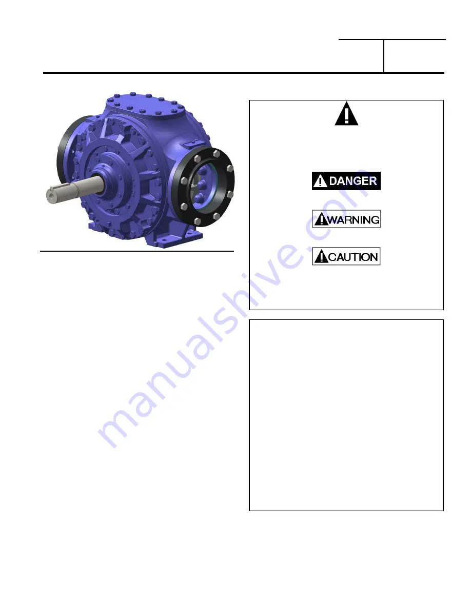
BLACKMER POWER PUMPS
960253
INSTRUCTIONS NO. 701-D00
INSTALLATION OPERATION AND MAINTENANCE INSTRUCTIONS
MODELS: CRL8A
Section
Effective
Replaces
701
Mar 2016
Jan 2014
PUMP DATA
Technical
Data
.......................................................
2
Initial Pump Start Up Information ........................... 2
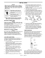
INSTALLATION
Pre-Installation
Cleaning
........................................ 3
Location
and
Piping
...............................................
3
Pump
Mounting
...................................................... 3
Coupling
Alignment
................................................ 4
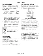
Pump
Rotation
.......................................................
4
To Change Pump Rotation .................................... 4
Check
Valves
.........................................................
4
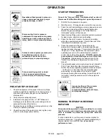
OPERATION
Pre-Start Up Check List ......................................... 5
Start Up Procedures .............................................. 5
Running the Pump in Reverse Rotation ................ 5
Flushing the Pump ................................................. 6
Relief Valve Setting and Adjustment ..................... 6
MAINTENANCE
Torque
Table
.........................................................
7
Scheduled
Maintenance
........................................
7
Strainers .......................................................... 7
Lubrication ....................................................... 7
Pump
Disassembly
................................................
8
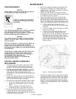
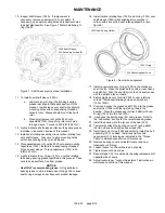
Seal/Bearing
Replacement
....................................
8
Complete Pump Disassembly .............................. 10
Pump
Assembly
...................................................
11
TROUBLE SHOOTING
................................................. 14
Numbers in parentheses following individual parts
indicate reference numbers on the Blackmer CRL8A
Parts List 701-D01.
Blackmer pump manuals and parts lists may be obtained
from Blackmer's website (www.blackmer.com) or by
contacting Blackmer Customer Service.
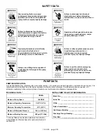
SAFETY DATA
This is a SAFETY ALERT SYMBOL.
When you see this symbol on the product, or in the
manual, look for one of the following signal words and be
alert to the potential for personal injury, death or major
property damage
Warns of hazards that WILL cause serious personal
injury, death or major property damage.
Warns of hazards that CAN cause serious personal
injury, death or major property damage.
Warns of hazards that CAN cause personal injury
or property damage.
NOTICE:
Indicates special instructions which are very
important and must be followed.
NOTICE:
Blackmer Power Pumps
MUST
only be installed in
systems, which have been designed by qualified
engineering personnel. The system
MUST
conform to all
applicable local and national regulations and safety
standards.
This manual is intended to assist in the installation and
operation of Blackmer Power pumps, and
MUST
be kept
with the pump.
Pump service shall be performed by qualified technicians
ONLY
. Service shall conform to all applicable local and
national regulations and safety standards.
Thoroughly review this manual, all instructions and
hazard warnings,
BEFORE
performing any work on the
pump.
Maintain
ALL
system and pump operation and hazard
warning decals.


