background image

THE POND MASTERS GUIDE TO 


POWERSAFE 2/3/4/5 


OUTLET 

SWITCHBOXES 


Congratulations on buying a Blagdon Powersafe Switchbox. The Powersafe range of 

switchboxes has been specifically designed to protect your pond equipment from failure. Each 

individual double pole switch gives total electrical isolation when switched off. Each switch 

features the unique at-a-glance power status indication system, which enables quick 

identification of power on, power on standby and power failure due to a blown fuse. Each switch 

has an individual fuse to provide overload protection ensuring that even if one or more items of 

equipment fail, the other essential pond equipment is still able to function. 


IMPORTANT 


Please attach proof of purchase to this manual and file in a safe place. 


CONTENTS 


Getting to know 


your Powersafe Switchbox

...................


Wiring diagram

 ............ 

inside front cover 


Parts description

 ........... 

inside front cover 


Spares codes

 .................................


Technical specification

 ......................


Installation

 ............................... 

3 - 7 


Mounting the Switchbox

 .....................


Electrical installation

 .................... 

4 - 7 


Maintenance

 ................................. 


Replacing a fuse

 ............................ 


Maintenance

 ................................ 


Faults problems procedure

 .................. 


Consumer advice contact details

 ............. 


Returning a faulty Switchbox

 ................ 

Summary of Contents for POWERSAFE 2

Page 1: ...ailure due to a blown fuse Each switch has an individual fuse to provide overload protection ensuring that even if one or more items of equipment fail the other essential pond equipment is still able to function IMPORTANT Please attach proof of purchase to this manual and file in a safe place CONTENTS Getting to know your Powersafe Switchbox 2 Wiring diagram inside front cover Parts description in...

Page 2: ...1 ...

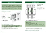
Page 3: ... Maximum power output 1 1000W 1000W 1000W 1000W Maximum power outputs 2 5 1x300W 2x300W 3x300W 4x300W POND PUMP FOR WATERFALLS FILTERS AND FOUNTAINS MAINS POWER SUPPLY AIR PUMP RCD SOCKET OR PLUG HOUSE SHED or GARAGE INPOOL LIGHTING Example shown is 5 way Powersafe Switchbox Power status indicator lights NO LIGHT Switch on or off Fuse has blown no power RED LIGHT Switch off power supply on standby...

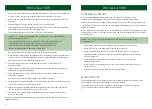
Page 4: ... supply is off and isolated Remove the Switchbox from the mounting bracket Unscrew the four screws at the back of the box to remove the Switchbox cover Place in a safe location INSTALLATION CIRCUIT BOARD REMOVAL Remove the circuit board by unscrewing the locating screws and wire each appliance before replacing and locating into the box 1 Prepare the cable see cable preparation diagram inside front...

Page 5: ...x 14 Identify the appliances installed with the labels provided in the recess above the relevant switch to enable clear identification when the box is in use 15 The unit can now be placed on the fixing bracket provided by sliding the box vertically down onto the bracket See power status indicator lights diagram page 2 for status of the Switchbox when the power is supplied to the unit INSTALLATION ...

Page 6: ...mary Fax 01306 876712 E mail customercare interpet co uk GUARANTEE This product is guaranteed against defects in material and workmanship for 2 years from the date of purchase under normal usage The guarantee DOES NOT APPLY in case of improper use negligence lack of maintenance or accidental damage to the Switchbox If the Switchbox fails due to a manufacturing fault within this period it will be e...

Reviews: