background image

www.blondertongue.com

Broad

B

and 

r

eference 

Guide

Rev 8.0

one Jake Brown road, old Bridge, nJ  08857

(732) 679-4000 

 fax (732) 679-4353

www.blondertongue.com

$8.95 u.S.a.

BLonder TonGue LaBoraTorieS, inc.

BroadBand


reference Guide

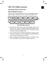
Summary of Contents for AMM-806

Page 1: ...ndertongue com Broadband Reference Guide Rev 8 0 One Jake Brown Road Old Bridge NJ 08857 732 679 4000 Fax 732 679 4353 www blondertongue com 8 95 U S A BLONDER TONGUE LABORATORIES INC BROADBAND REFERENCE GUIDE ...

Page 2: ...ious versions of the reference guide on the Blonder Tongue website We welcome any suggestion for further improvement simply e mail feedback blondertongue com Bob Pallé President One Jake Brown Road Old Bridge NJ 08857 732 679 4000 Fax 732 679 4353 www blondertongue com 2008 Blonder Tongue Laboratories Inc All rights reserved Specifications are subject to change without notice Trademarks are the pr...

Page 3: ...Set Up Instruction Guide 36 DAP Digital to Analog Processor 37 DAP Quick Set Up Instruction Guide 49 QT Modular QPSK QAM Transcoder 50 QPSK QAM Transcoders 53 Broadband Amplifier Specifications Chart 58 Directional Couplers Insertion Loss 59 MegaPort Components 60 Addressable Products 68 Jamming Capability 69 VMI System Design 70 TVCB Systems Design 72 TVCB Installation 75 TVCB PC Parental Control...

Page 4: ...100 20 Log Function Derate Chart 113 10 Log Function Derate Chart 114 Combining Two X MOD or CTB Performance Ratings 20 Log 115 Combining Two CNR or SSO Performance Ratings 10 Log 115 Beat Packet Quantity 116 Fiber Optics 118 Frequency Charts 125 CATV Channels North America 126 CATV QAM Channel Center Frequency 54 MHz to 860 MHz 130 Off Air Channels North America CCIR Standard M NTSC 132 PAL B Cha...

Page 5: ...Aeronautical Band Frequencies 151 North American Satellite C Ku Band 152 Programming Services 153 Conversion Factors 155 Ohm s Law Joule s Law 155 Table of Conversions 156 Return Loss Reflection Coefficient and Voltage Standing Wave Ratio VSWR 158 Return Loss Ratio RLR 159 Conversion Factors 160 Temperature Conversion Nomograph 164 Wire Gauge Data AWG 165 Current Ratings for Electronic Cables 166 ...

Page 6: ...tants 177 75 Ohm Attenuator Table Equations 177 Ghosts 179 Echo Rating Graph 180 Signal to Interference Limits Non Coherent Carriers 181 Error Corrections Chart 182 Heterodyne Modulator Analog 183 Heterodyne Processor Analog 184 Broadband RF Network Powering 185 FCC Rules 187 Cumulative Leakage Index 187 Maximum Leakage Levels 189 Highlights of FCC Rules Regulations Part 76 192 Broadband Communica...

Page 7: ...7 Antenna Stacking 208 Antenna Spacing 209 Antenna Spacing Chart 210 Antenna Phasing 211 Pre Amp Noise Figure vs Carrier To Noise 212 System Planning 213 Headend HVAC Considerations 213 Digital Signal Analysis 215 Station List 224 Acronyms 274 How to Reach Blonder Tongue 277 Table Of Contents cont vi ...

Page 8: ...oing research and development efforts to enable the delivery of such services over packet based Internet Protocol networks of the future The Company serves both the franchised and private cable markets and is a provider of integrated network solutions to all of the related video markets including the multi dwelling unit MDU market the lodging hospitality market and the institutional market consist...

Page 9: ...ch as 8VSB QAM Demodulators Digital to Analog Processors QPSK QAM Transcoders Integrated Receiver Descramblers Commercial Satellite Receivers Commercial Digital Satellite Receivers Agile Audio Video Modulators Channelized Audio Video Modulators Channelized Agile Audio Video Modulators Modular Headend Systems Agile Heterodyne Processors Agile Audio Video Demodulators Stereo Encoders Combiners 8VSB ...

Page 10: ... 90 Channelized No 55 dBmV Maximum Frequency Broadband IF Output Analog MHz Noise Type Loops Level Modulators Processors AP 60 550B 806 550 76 Agile Single 60 dBmV AP 60 750B 806 750 76 Agile Single 60 dBmV AP 40 550B 806 550 76 Agile Single 40 dBmV AP 40 750B 806 750 76 Agile Single 40 dBmV Maximum Frequency MHz Broadband IF Output Analog Input Output Noise Type Loops Level AQM 860 75 Agile No 40...

Page 11: ...orresponding value of the switch The values are then added and equated into a channel number by the unit microprocessor A simple chart shown on the next page gives the corresponding switch position for numbers 1 to 12 The user then sets the Tens section and the Ones section together to reflect the desired channel Example For CH 116 you set 11 Tens and 6 ones for 116 For single digit channels the T...

Page 12: ...1 5 6 7 8 9 10 11 12 8 4 2 1 SWITCH 2 Tens Ones 00 12 0 9 8 4 2 1 Examples CH 2 CH 58 CH 87 CH 116 For previous AP AD 1 model switch settings see the Reference Card with the unit or please visit our website www blondertongue com switchsettings Below are examples of the switch settings ...

Page 13: ...put to permit the easy interface with any equipment which accepts baseband video audio inputs such as TV displays or existing Blonder Tongue analog modulators Features 8VSB QAM 64 QAM 256 Annex B Modulated RF Input Transport Streams Supported Modular Compact Units Permit High Density 8 Modules in 3 Rack Height Easy Set up Configuration via Front Panel LCD Controls Remote Computer Control Capabilit...

Page 14: ...ck to the RF input signal Flashing Green LED Indicates Not Locked or Scanning in process 2 Backlit LCD 1 6 character 2 line Liquid Crystal Display screen used to interact with user to display unit information 3 Push Button Navigation Controls B uttons used to navigate between menus and operate the units 4 9 Pin RS 232 Connector U sed for Future AQD Module upgrade only ...

Page 15: ... RS232 Serial Data Ports U sed to plug into and daisy chain AQD units for remote monitoring and configuration 5 Power IN 12 pin female connector used to plug in the optional Standby Power unit 6 Video OUT NTSC Composite Video output via F Connector 7 8VSB QAM INPUT R F Connector for feeding appropriate 8VSB off air or QAM modulated RF input signal 8 Left Right Audio OUT RCA Connectors for Left Rig...

Page 16: ...unique module address that is set at the factory which is displayed immediately following the primary or secondary power source status This address is used for remote software capability only 2 Each module status is identified and reported on the LCD If a module is identified it is listed as PRESENT or NOT PRESENT if not connected or identified by the PCM 3 Upon completion of the boot up sequence ...

Page 17: ...e any of the arrow keys The diagram is divided into 8 rows to reflect the eight respective modules that can populate the rack chassis Information for Modules Not Present is not displayed during the loop sequence AQD Left Right Sequence The Left Right Sequence will display two basic LCD screens for each installed module This information will be displayed when a user depresses the t L or u R arrow n...

Page 18: ...ally being detected NO SIGNAL indicates that the input signal was not detected no RF input PLEASE SCAN indicates a scan was not performed or is required again AUDIO ONLY indicates no video signal NO AUDIO indicates no audio signal present SCRAMBLED PRG indicates the signal has encryption NOTE The AQD Not Present message will be displayed when the optional Remote Configuration Server RCS Module is ...

Page 19: ...eys on the front of the control module The user may scroll through the menu screens depicted by continuing to press the up and down navigation keys The following diagram depicts the available variables with the modify options listed below See the following page for specific variable function details AQD LCD Interactive Variable Sequence ...

Page 20: ...g cursor is displayed 4 After the blinking cursor is displayed the user simply presses the UP or DN arrow buttons to increment or decrement to the appropriate desired value 5 When the user reaches the desired value the user should press the ENTER button again to apply the change to the PCM memory The PCM then programs the corresponding module to the new setting 6 The LCD displays an affirmative re...

Page 21: ...atically set when the QAM B mode is selected in the Demod Mode command menu Reception is limited to CATV center frequencies o It is only required to choose the HRC or IRC option when these frequency off sets are used with the CATV plan NOTE See Appendix for additional details SCAN MENU The scan menu command allows the AQD module to auto search for available programming It is required that each mod...

Page 22: ...riefly display a banner at the top of the screen The banner contains the major minor sub channel designation and the time time displayed comes from the broadcast stream AQD STATUS The AQD Status command screen displays valuable status information on the selected program channel Signal Status A LOCK is indicated when a valid signal acquisition has been achieved by the AQD module as well as the sign...

Page 23: ...and left right to fit the screen ZOOM 1 has a vertical horizontal cut with black bars ZOOM 2 has a vertical horizontal cut without black bars SMART ZOOM 1 is a modified version of Zoom 1 to adjust to differences in the picture shape data sent by a broadcaster SMART ZOOM 2 expands the image to fit the screen while cropping some images on the left right and presents without black bars NOTE See Appen...

Page 24: ...ndard for Closed Captioning for NTSC Broadcasts in the United States An operator can globally enable or disable closed captioning for each module eliminating the need to adjust individual TV viewing locations AQD PWR RESET The AQD Power Reset command allows an operator to reset the power or cold boot an individual or all the modules installed in a rack To perform a reset for a single module naviga...

Page 25: ...re connected to the correct location on the PCM and the respective modules to ensure proper communication 3 Program the appropriate DEMOD MODE for each module 8VSB or QAM Refer to page 16 for detailed variable instructions 4 Program the appropriate CHANNEL PLAN for each module Broadcast Standard CATV HRC or IRC 5 Perform a SCAN on each or all modules itisnotrecommended to operate the unit when a s...

Page 26: ...s a custom design approach utilizing the latest generation technology available to ensure extremely low phase noise and a highly stable output signal This eliminates the hassles and potential for problems caused by module based interconnects especially when using products without integrated upconverters The AQM is easily accommodated in Blonder Tongue s standard HE Series of micro modular rack cha...

Page 27: ...r to deliver power 2 ASI IN BNC connector for ASI Asynchronous Serial Interface input 3 RF OUT 75 Ohm QAM RF Output Unit Front Panel Unit Rear Panel Boot Up Display Sequence When the unit is in Normal Mode and is first plugged in for use the AQM checks for the presence of input data If data is not detected it displays the appropriate module condition on the LCD readout as depicted below If unit is...

Page 28: ...l the core module programming is performed This sequence is accessed anytime a user depresses one of the t L or u R and UP DN arrow navigation keys The following diagram depicts the LCD screens available in the main interactive sequence Note Factory Reset Default values depicted in illustration ...

Page 29: ...e then the corresponding AQM module stores the new information Interactive Sequence Detail QAM Mode The AQM can be set to comply with the ITU TJ 83 Annex A Annex B specifications ITU A is used for DVB operation ITU B is used for DigiCiper II operation Encoder The Encoder selection is only used in ITU A Mode If set to ITU B Mode then the Encoder shows NONE QAM The QAM modulation type is user select...

Page 30: ...is fed to the module via the BNC connector on the rear panel ASI Asynchronous Serial Interface data is typically used The unit is also programmed with the ability to generate a PRBS Pseudo Random Binary Sequence test signal The PRBS signal is a polynomial sequence that is determined by the Input Selection choice The following settings are available PRBS 25M PRBS 23 PRBS 15M PRBS 15 These selection...

Page 31: ... decrement to the appropriate desired value for each digit press and hold the button to quickly scroll QAM Out The unit has three QAM modes NORMAL The NORMAL QAM mode outputs a QAM modulated signal OFF The OFF QAM mode outputs no signal from the module CW The CW QAM mode outputs a CW signal that is very useful for measuring the output level of the unit See the QAM Signal Level Testing section for ...

Page 32: ...tory default setting To perform this function press and hold the ENTER and DN arrow navigation keys simultaneously until the LCD displays Factory Reset and then release This will cause the unit to reset the programmed information to the factory default settings shown in the Main Interactive Sequence illustration on page 10 Factory Reset This will reset all programming information for the unit and ...

Page 33: ...nt RF QAM channel Complete regeneration of a QAM input for optimal MER performance Convert one off air ATSC 8VSB signal to a QAM output Features 8VSB 16VSB Annex A QAM 16 32 64 128 256 and Annex B QAM 64 256 Modulated RF Input Transport Streams Supported Modular Compact Units Permit High Density 8 Modules in 3 Rack Height Easy Set up Configuration via Front Panel LCD Controls Remote Computer Contr...

Page 34: ...tes valid lock to the RF input signal and valid lock to the RF output Flashing Green LED I ndicates not locked status on either RF input or RF output 2 Backlit LCD 1 6 character 2 line Liquid Crystal Display screen used to interact with user to display unit information 3 Push Button Navigation Controls B uttons used to navigate between menus and set variables ...

Page 35: ...female connector Use supplied power data cables to connect the PCM unit to the appropriate module ensure proper wiring by module number slot 4 R S232 Serial Data Ports Used to plug into and daisy chain AQT PCM units for remote monitoring and configuration 5 S tandby Power In 12 pin female connector used to plug in the optional Standby Power unit 6 Q AM RF Out RF Connector with QAM modulated output...

Page 36: ...is identified and reported on the LCD If a module is identified it is listed as PRESENT or NOT PRESENT if not connected or identified by the PCM 3 The AQT NOT PRESENT message will be displayed when the optional Remote Configuration Server RCS Module is installed in a particular chassis slot 4 Upon completion of the boot up sequence the AQT PCM is ready for use and will proceed to the loop display ...

Page 37: ...ny of the arrow keys In the loop sequence the back light LCD is off however after pressing any navi gationbuttonthebacklightautomaticallyturnsonforeaseofviewing During the loop sequence the LCD displays 3 valuable parameters for each installed present AQT module Modules not present will not have information displayed during the loop sequence Input Displays the actual input signal to noise ratio SN...

Page 38: ... Details The Left Right sequence is where the core variables of the AQT are programmed It is accessed when a user depresses the t L or u R arrow navigation keys There are 4 main adjustable variables for each module AQT LCD Left Right Variable Sequence ...

Page 39: ... o NORMAL The NORMAL QAM mode outputs a 6 MHz QAM modulated signal and must be used with 8VSB input o OFF The OFF QAM mode outputs no signal from the module When a module is placed in the QAM off mode the status LED indicator will blink o CW The CW carrier wave mode outputs a CW signal that is very useful for measuring the output level of the unit the CW signal is a true representation of the QAM ...

Page 40: ... the t L or u R arrow navigation keys to scroll to the installed module you desire to adjust 2 Press the UP or DN arrow navigation keys to scroll to the desired interactive variable 3 When a user arrives at a screen whose variable needs to be changed the user should depress and hold the ENTER button until the blinking cursor is displayed 4 After the blinking cursor is displayed the user simply pre...

Page 41: ...the adjustable settings are issued to the particular module that is actively displayed Some variables are global for the unit and not module specific The user may scroll through the menu screens depicted by continuing to press the up and down navigation keys The following diagram depicts the available advanced variables with the modify options listed below AQT LCD Interactive Variable Sequence ...

Page 42: ...e appropriate alpha setting to match the output QAM mode INTERLEAVER permits the entry of the appropriate interleaver setting to match the output QAM mode OUT BD RATE permits the entry of the desired output QAM baud rate The QAM output baud rate is automatically set to the corresponding values for the respective input baud rate as listed in the chart below AQT ATSC to QAM Transcoder VSB 8 5 3811 M...

Page 43: ...ignal acquisition range is 20 to 20 dBmV 10 to 10 dBmV is the desired optimum level 3 Program the desired Input Frequency for each appropriate module Tuning Range 54 864 MHz 4 Program the desired Output Channel for each appropriate module Tuning Range CATV 2 135 a 40 dBmV is recommended for optimum level for SNR performance 5 Verify the Module Lock state Press the u R arrow key until the SNR value...

Page 44: ...daisy chained in the headend The DAP supports standard EIA CATV IRC HRC and Broadcast channel plans in the 54 864 frequency range All channel frequency information with appropriate FCC offsets is pre programmed and tuned electronically via microprocessor The unit is also equipped with the Emergency Alert System EAS feature which can also be used as an alternate IF input Features Decodes HDTV or SD...

Page 45: ...ural carrier is over 25 kHz 6 A udio Modulation Level Adjusts aural carrier modulation 7 A ural Carrier Controls amplitude of aural RF carrier relative to visual RF carrier 8 V ideo Modulation Level Adjust percentage of modulation 9 V ideo Over Modulation LED Lights when modulation is above 87 5 10 E thernet Link Receive and Transmit LED LED indicator for optional ethernet connectivity The LED s w...

Page 46: ...t 6 IF OUT F Connector IF Output 7 EAS ALT IF F Connector for Emergency Alert System ALT IF 8 EAS ALT IF Terminal Strip Terminal Connector for Auto Manual EAS 9 O ptional RS232 Computer Control RJ 11 Connector used to daisy chain DAP for optional computer control Requires Remote Network Card not shown to be installed in one DAP unit per headend 10 8 VSB QAM INPUT RF Connector for feeding appropria...

Page 47: ... which is displayed immediately following the power status initialization This address is used for remote software capability only 2 Upon completion of the boot up sequence the DAP is ready for use and will proceed to the loop display sequence DAP Digital to Analog Processor Boot Up Display Sequence DO NOT push any switches on the control module during this sequence as it will NOT respond until it...

Page 48: ...sed in dB The following are the desired input SNR ranges for the appropriate signal modulation type NO SIGNAL indicates that the input signal was not detected no RF input PLEASE SCAN indicates a scan was not performed or is required again AUDIO ONLY indicates no video signal NO AUDIO indicates no audio signal present SCRAMBLED PRG indicates the signal has encryption NO PROGRAM will be displayed if...

Page 49: ...tive menu is easily accessible by depressing the p UP or q DN arrow keys on the front of the DAP unit The user may scroll through the menu screens depicted by continuing to press the up and down navigation keys The following diagram depicts the available variables with the options listed below See the following page for specific variable function details DAP Digital to Analog Processor DAP Left Ri...

Page 50: ...emory The control board then programs the unit to the new setting 5 The LCD displays an affirmative response after information is entered correctly for several of the variables The controller will display the Entry Accepted response as demonstrated below Variable Details INPUT DEMOD MODE The DAP is capable of locking to a terrestrial off air 8VSB or CATV QAM Annex B modulated RF input signal The s...

Page 51: ...red to choose the HRC or IRC option when these frequency off sets are used with the CATV plan SCAN MENU The scan menu command allows the DAP unit to auto search for available programming It is required to perform a scan in order to function properly YES The YES command performs a scan of the incoming available signals by the DAP unit STATUS The STATUS command displays the channels found during the...

Page 52: ...The LCD will show the ENTRY ACCEPTED message and all TV s will briefly display a banner at the top of the screen The banner contains the major minor sub channel designation and the time time displayed comes from the broadcast stream INPUT STATUS The Input Status command screen displays valuable status informa tion on the selected program channel Signal Status A INPUT LOCK is indicated when a valid...

Page 53: ...lack bars SMART ZOOM 1 is a modified version of Zoom 1 to adjust to differences in the picture shape data sent by a broadcaster OUTPUT AUDIO The output volume can be adjusted within a range of 0 to 100 AUDIO LANGUAGE The audio language command allows for the selection of an available primary or secondary audio program Primary only Detects only a primary audio feed Primary Plus Language The unit wi...

Page 54: ...t used in typically deployments and only intended for special applications such as PAL usage OUTPUT LEVEL The RF OUTPUT level is user adjustable by pressing the p UP or q DN arrow buttons The output level is not changed until the ENTER button is pressed The level increments in 0 2 dB steps Pressing and holding the p UP or q DN buttons will allow for faster scrolling The display range is 48 62 dBmV...

Page 55: ...the highlights white portions of the picture to become washed out AUDIO LEVEL Turn the Audio Level adjust control clockwise until the Audio Overmodulation light just flashes slightly on the loudest peaks of the audio program material AURAL CARRIER To adjust the aural to visual carrier ratio adjust the Aural Carrier control to obtain the desired Aural Carrier level Recommended ratio is 15 dB EAS AL...

Page 56: ...ppropriate DEMOD MODE for each module 8VSB or QAM Refer to page 13 for detailed variable instructions 3 Program the appropriate CHANNEL PLAN for each module Broadcast Standard CATV HRC or IRC 4 Perform a SCAN it is not recommended to operate the unit when a scan is in process a A scan must also be performed each time the DEMOD MODE is changed 5 Program the appropriate desired channel in the TUNE C...

Page 57: ... to a 6 MHz wide QAM modulated IF signal and translates it to any CATV RF channel assignment in the 54 864 MHz frequency band The QT Series features a back lit LCD display with front panel accessible push button controls providing access to all vital unit information facilitating easy set up and troubleshooting Interfacing the QT with Blonder Tongue s QCentral computer software provides off site r...

Page 58: ... Pause OFF Indicates possible upconverter problem or possible problem with power cable d F lash 4x and Pause OFF Indicates possible QAM modulator problem check input transponder frequency and data rate to correct check to make sure in Auto Mode 2 Backlit LCD 8 character 2 line Liquid Crystal Display screen used to interact with user to display unit information 3 Push Button Navigation Controls But...

Page 59: ... Serial Data Ports U sed to plug into and daisy chain QT units for remote monitoring and configuration 5 Power IN 12 pin female connector used to plug in the optional Standby Power unit for redundant support 6 QPSK L Band Input I ndependent 75 Ohm RF connector for feeding appropriate QPSK L Band satellite input signal 7 QAM RF Output Independent 75 Ohm QAM RF Output 8 Power Data 12 pin female conn...

Page 60: ...ctions and displays the appropriate module condition on the LCD readout as depicted below Boot Up Display Sequence Upon completion of the boot up sequence the transcoder is ready for use and will proceed to the loop display sequence DO NOT push any switches on the module during this sequence as it will not respond until it displays or QTM IS READY CAUTION ...

Page 61: ...sed again to save the change The control module then programs the corresponding transcoder module to the new information 4 The unit displays an affirmative response after information is entered correctly The controller will display the Entry Accepted response as demonstrated below 5 Entries can be made to the controller for all modules even if not all modules are installed The controller will disp...

Page 62: ...AM Modes CW ALL Puts all QTM or QTM HD installed in rack chassis into CW mode for ease of level adjustment NORMAL ALL Puts all QTM or QTM HD installed in rack chassis into normal QAM mode Output Level The transcoders features electronic output level control for each of the single transcoder modules The output level can be adjusted in any of the QAM modes listed above The output level is displayed ...

Page 63: ...store it to it s factory default setting To perform this function press and hold the UP and DN arrow navigation keys simultaneously until the LCD displays Factory Reset and then release This will cause the unit to reset the programmed information to the factory default setting shown on the next page This will reset all programming information for all modules CAUTION Factory Reset ...

Page 64: ...INPUT 974 MHz QAM NORMAL LEVEL 40 dBmV 4 OUT CH 104 4 INPUT 974 MHz QAM NORMAL LEVEL 40 dBmV 5 OUT CH 105 5 INPUT 974 MHz QAM NORMAL LEVEL 40 dBmV 6 OUT CH 106 6 INPUT 974 MHz QAM NORMAL LEVEL 40 dBmV QT Series 7 OUT CH 107 7 INPUT 974 MHz QAM NORMAL LEVEL 40 dBmV 8 OUT CH 108 8 INPUT 974 MHz QAM NORMAL LEVEL 40 dBmV MODE AUTO DECODER DVB IN RATE 20 000 M QAM 128 ALPHA 15 INTERLV I12 J17 BD RATE 4...

Page 65: ... 36 44 77 63 5800 73 BIDA 75A 30 49 750 32 10 8 8 5 36 44 110 60 5800P73 BIDA 75A 30P 49 750 32 10 8 8 5 36 44 110 64 5800 74 BIDA 75A 43 49 750 43 10 8 8 5 36 44 110 56 5800P74 BIDA 75A 43P 49 750 43 10 8 8 5 36 44 110 64 5800 83 BIDA 86A 30 49 860 32 10 8 8 5 36 44 129 54 5800P83 BIDA 86A 30P 49 860 32 10 8 8 5 36 44 129 62 5800 84 BIDA 86A 43 49 860 44 10 8 8 5 36 44 129 56 5800P84 BIDA 86A 43P...

Page 66: ...8 26 1948 29 1948 32 1948 35 3 8 2 1 1 3 0 8 0 7 0 6 0 6 0 6 4 3 2 3 1 8 1 2 1 0 0 8 0 8 0 8 11 14 17 20 23 26 29 32 35 Terminated THRU LINE LOSS dB Please refer to the Blonder Tongue catalog for more detailed specifications common to indoor and outdoor passives DMT 1000 2 MODEL STOCK NO 450 MHz 1000 MHz 3852 4 1 2 2 1 7 1 4 1 0 1 0 1 0 1 0 1 0 1 0 4 8 3 7 2 4 2 2 1 5 1 5 1 5 1 5 1 5 1 5 4 8 11 14...

Page 67: ... RF Connector LAN Ethernet Port WAN Power Cable The connection to the LAN Port will be made directly with a cross cable via MegaPort manager or http web interface The Port ID is 172 16 70 1 C Class MegaPort Intelligent Outlet MPO Replacing ordinary TV outlets the IO is connected to the coax infrastructure providing TV and network connections 10BaseT USB An MPO may be installed complementary to an ...

Page 68: ...BSF Double Tap Upstream and Downstream Signal Settings Frequency Diversity Frequency Diversity is when each MPG DS and US carrier are set at a different frequency This is typically used when multiple MPG s are on the same cable leg Frequency Re Use Frequency Re Use is when each MPG DS and US carrier are set at the same frequency This can only occur when MPG s are not on the same cable leg ...

Page 69: ...s to be installed in the connection properties Ethernet TMT Management Protocol Driver USB Ndisuio inf protocol In order to see data of the IO MPO components go to the Summary tab You can see the version of the IO hardware and software the IO MAC address or serial number its ID and other parameters as shown in the screenshot For more information please refer to the User s Manual ...

Page 70: ...63 MegaPort Manager MegaPort Manager Main Screen with MPO s installed Note Visit the Blonder Tongue FTP Site for the latest software releases and updates at ftp ftp1 blondertongue com ...

Page 71: ...lick the Downstream or Upstream tab MegaPort Manager RF Data MPG Downsteam Center Frequency MPG Transmission Power MPG Downsteam Modulation MPO Downsteam Center Frequency MPG Downsteam Bandwidth MPG Downsteam Symbol Rate Note If DS parameter is being changed you have to change the same parameter manually in every IO with the ConfigIO software ...

Page 72: ...t Manager IO Upstream Frequency IO Upstream Bandwidth IO Upstream Symbol Rate IO Upstream Modulation MPG Receiving Level Note If US parameter is being changed the change will take effect for the IO automatically ...

Page 73: ...n it could mean that the SNMP Session parameters Time Out or No of Retries are too low You can change this in the Application Setting form which can be opened from the View Settings menu or using Ctrl T F5 and the Refresh toolbar button don t refresh all data presented in the main window They refresh only data that are likely to change such as counters To make a full refresh you must click on the ...

Page 74: ...ction check the cable is connected properly 4 Press the Monitor RF status tab and observe if the upstream power is stable If it is not stable check for US RF problem 5 On the PC observe that the IO NETWORK DEVICE receives an IP from the DHCP server Open a DOS window type ipconfig release and then ipconfig renew 6 In the ConfigIO software go to IO settings click the Automatic US Power Uncheck the b...

Page 75: ...at the headend as with conventional scrambling systems There are four addressable product lines VideoMask Interdiction VMI TV Channel Blocker TVCB TV Channel Blocker Parental Controlled TVCB PC Subscriber Module Interdiction SMI Formerly known as Scientific Atlanta addressable interdiction system Addressable Multi Port Tap Interdiction Unit AMT For each product line the following information is pr...

Page 76: ...annels 650 MHz 450 MHz 300 MHz 216 MHz 174 MHz 120 MHz 550 MHz 600 MHz Highband Midband Lowband Osc 1 Chs 99 14 22 7 Osc 3 Chs 29 40 Osc 4 Chs 39 50 Osc 5 Chs 49 62 Osc 6 Chs 61 74 Osc 2 Chs 8 13 23 28 12 channels Osc 8 Chs 2 6 5 channels 54 85 MHz 114 177 MHz 180 249 MHz 252 321 MHz 312 381 MHz 372 453 MHz 444 453 MHz 12 channels 14 channels 14 channels 14 channels 600 MHz 450 MHz 550 MHz 300 MHz...

Page 77: ...0 67 0 90 0 0 00 0 00 0 00 0 00 0 00 1 1 07 1 52 1 23 0 60 0 46 2 1 89 2 23 1 24 0 16 0 35 3 2 88 3 05 1 38 0 10 0 17 4 3 47 3 81 2 01 0 79 0 35 5 3 86 4 35 2 13 0 94 0 49 6 4 45 4 85 2 32 0 80 0 40 7 5 42 5 67 2 42 0 62 0 25 8 5 99 6 37 2 00 0 79 0 38 9 7 08 7 21 2 68 0 68 0 13 10 7 47 7 89 2 94 0 90 0 43 11 8 21 8 55 3 24 0 96 0 34 12 9 01 9 25 1 60 0 51 0 24 13 9 85 10 27 4 00 1 32 0 42 14 10 7...

Page 78: ...515 50 00 330 375 465 55 00 310 355 420 60 00 295 360 390 65 00 240 315 385 70 00 230 300 360 75 00 220 285 340 80 00 205 265 325 85 00 195 255 310 90 00 190 245 295 Current Consumption mA Pin 7 6 5 4 3 2 1 Voltage 28 VDC NOT 12 VDC GND 6 2 VDC GND 60 VAC Minimum 26 0 USED 11 4 6 1 45 Maximum 30 0 12 6 6 3 60 Power Supply Pinout NOT USED ...

Page 79: ... 1 38 0 10 0 17 4 3 47 3 81 2 01 0 79 0 35 5 3 86 4 35 2 13 0 94 0 49 6 4 45 4 85 2 32 0 80 0 40 7 5 42 5 67 2 42 0 62 0 25 8 5 99 6 37 2 00 0 79 0 38 9 7 08 7 21 2 68 0 68 0 13 10 7 47 7 89 2 94 0 90 0 43 11 8 21 8 55 3 24 0 96 0 34 12 9 01 9 25 1 60 0 51 0 24 13 9 85 10 27 4 00 1 32 0 42 14 10 76 10 89 1 37 0 36 0 14 15 11 18 11 30 1 40 0 36 0 13 16 12 04 12 29 1 63 0 55 0 25 17 12 69 12 87 1 50...

Page 80: ... of ways 1 House powered via 120VAC outlet Power consumption 11 8W 24VAC 550 mA 2 Auxiliary or Line Powered Power consumption 8 0W 60VAC 200 mA 8 8W 90VAC 150 mA Below are the power consumptions of the TVCB Volts Curr Watts 24 00 580 mA 11 8 60 00 200 mA 8 0 90 00 150 mA 8 8 ...

Page 81: ...74 TVCB Systems Design Power Selection Forward Attenuator Power Select RF In 60 90 Aux Power Return Attenuator RF Out Equalizer Power Supply RF Board Jammer Controller Board ...

Page 82: ...k Powering Position B 26 VAC House Powering P1 J 11 P1 J 12 P1 J 13 P2 J 14 Feeder Power P1 J 11 P1 J 12 P1 J 13 P2 J 14 House Power 3 2 P1 J 11 P1 J 12 P1 J 13 P2 J 14 Auxillary Power 2 1 3 2 P1 P2 Power Selection TVCB Installation ...

Page 83: ...g Sequence TVCB Installation Tamper 1 Flash of Disconnect Unit Time Out 2 Flashes of Disconnect Unit Address 3 Flashes of Disconnect Calibration 4 Flashes of Disconnect EEPROM 5 Flashes of Disconnect Fault Action Pulse Disconnect Pulse Disconnect has the following codes to identify which fault has occurred TVCB Troubleshooting ...

Page 84: ... necessary to prevent unwanted channels from being viewed The TVCB PC provides channel blocking ch 2 86 to all televisions in the dwelling The TVCB PC is a stand alone unit that has push button control inside that allows you to change blocked channels quickly and easily without cable company reprogramming Note The TVCB PC Self Install Consumer 9111 is an end user ready unit conditioned for home in...

Page 85: ...Input Requirements 9 0 dBmV 54 MHz Ch 2 15 0 dBmV 550 MHz Ch 78 5 If required for application select Attenuator AT Equalizer EQ from chart 5 Items 6 9 are not required for the 9111 6 Plug in appropriate EQ and Fwd AT 7 Verify AGC Voltage 3 1 VDC optimum 3 0 3 2 VDC acceptable 8 Verify unit RF Output Levels Subscriber Port Output 10 0 dBmV 54 MHz Ch 2 16 0 dBmV 600 MHz Ch 78 9 Adjust EQ and AT if n...

Page 86: ...79 TVCB PC Installation ...

Page 87: ...upply board to select between 26 or 60 90 VAC input TVCB PC Installation Automatic Gain Control Broadband AGC using carriers in 140 240 MHz range with dynamic range of 3 dB Power Supply Jumper Determines Voltage B A PS Jumper From Factory Set to B A 60 90 VAC B 26 VAC House Please refer to the Instruction Manual for further information TVCB PC Troubleshooting In case of failure the small round LED...

Page 88: ... 4 1 4 2 1 2 4 12 0 562964 1 4 1 0 0 8 1 3 1 7 13 5 562965 1 4 1 0 0 8 1 3 1 7 15 0 562966 1 2 0 8 0 8 1 3 1 7 16 5 562967 1 2 0 8 0 7 1 1 1 4 18 0 562968 1 3 0 8 0 7 1 1 1 4 19 5 562969 1 3 0 8 0 7 1 1 1 4 21 0 562970 1 3 0 8 0 7 1 1 1 4 22 5 562971 1 3 0 8 0 7 1 1 1 4 24 0 562972 1 3 0 8 0 7 1 1 1 4 25 5 562973 1 3 0 8 0 7 1 1 1 4 27 0 562974 1 3 0 8 0 7 1 1 1 4 28 5 562975 1 3 0 8 0 7 1 1 1 4 3...

Page 89: ... 6 13 3 13 4 16 5 562967 16 4 17 1 17 0 14 8 14 6 18 0 562968 17 8 18 4 18 4 15 1 14 3 19 5 562969 19 6 20 2 20 2 16 4 15 6 21 0 562970 20 9 21 4 21 4 17 1 15 9 22 5 562971 22 3 22 9 22 9 18 3 16 9 24 0 562972 23 9 24 5 24 5 19 5 17 8 25 5 562973 25 5 26 1 26 2 21 5 20 3 27 0 562974 26 8 27 4 27 4 22 1 20 5 28 5 562975 28 3 28 8 29 0 22 8 20 4 30 0 562976 29 8 30 3 30 5 23 4 20 5 31 5 562977 30 9 ...

Page 90: ... 1 1 3 1 5 0 0 566057 0 1 0 1 0 2 1 5 562978 1 9 1 2 0 9 3 0 562979 2 9 1 3 0 8 4 5 562980 4 1 1 5 0 8 6 0 562981 5 4 1 8 0 9 7 5 562982 6 5 1 9 0 7 9 0 562983 7 5 2 1 0 7 10 5 562984 8 8 2 5 0 9 12 0 562985 10 0 2 9 1 0 13 5 562986 11 4 3 4 1 3 15 0 562987 12 2 3 3 0 9 16 5 562988 13 6 3 8 1 0 18 0 562989 14 7 3 8 0 8 19 5 562990 15 6 4 0 0 9 EQ Value Stock 51 MHz 550 MHz 750 MHz ...

Page 91: ...0 30 13 44 60 00 0 07 2 88 0 17 8 04 0 28 13 30 65 00 0 06 3 04 0 16 8 06 0 26 13 17 70 00 0 06 3 04 0 15 8 25 0 24 13 43 75 00 0 06 3 04 0 15 8 44 0 23 13 69 80 00 0 07 3 15 0 14 8 52 0 22 13 81 85 00 0 07 3 25 0 14 8 61 0 21 13 94 90 00 0 07 3 36 0 13 8 69 0 21 14 07 Housing Only w 2 Module w 4 Modules Volts Current Watts Current Watts Current Watts Measurements are adjusted to compensate for ch...

Page 92: ...00 0 17 5 20 0 32 10 36 0 50 16 24 45 00 0 15 5 15 0 28 10 40 0 43 15 75 50 00 0 14 5 27 0 26 10 50 0 50 18 80 55 00 0 13 5 40 0 25 10 61 0 36 15 65 60 00 0 13 5 48 0 23 10 71 0 34 15 77 65 00 0 13 5 57 0 22 10 82 0 32 15 90 70 00 0 13 5 85 0 22 11 08 0 30 16 03 75 00 0 13 6 13 0 21 11 34 0 29 16 17 80 00 0 13 6 44 0 21 11 66 0 28 16 31 85 00 0 13 6 76 0 21 11 98 0 26 16 45 90 00 0 13 7 08 0 20 12...

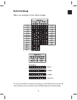
Page 93: ...86 SMI Installation Torque Patterns 1 Start Here 2 3 4 5 6 1 Start Here 2 3 4 4 PORT 8 PORT ...

Page 94: ...7 SMI Installation Strand Mount 4 port Configurations Pedestal Mount 4 port Configurations Signal Direction Forward Signal J1 In J2 Thru RECOMMENDED J2 Thru J1 In Foward Signal Foward Signal RECOMMENDED ...

Page 95: ... remaining DCs 4 31 5 dB are non terminating DC s 1 2 PS 3 4 Scenario 1 Scenario 2 Scenario 3 Scenario 4 DC Value 4 31 5 dB 4 31 5 dB 4 31 5 dB 0 1 2 3 dB AC Termination No Yes Yes Yes RF Termination No No Yes Add 75 Yes DC Ohm Term Term Input Seizure Block J1 or J2 J1 Only J1 Only J1 Only Jumper Configuration P1 Leave P1 Leave P1 Leave P1 Pull P2 Leave P2 Pull P2 Leave P2 Leave P5 Discard P5 Disc...

Page 96: ...module P N 564265 If 750 MHz housing is equipped with a You can use non power passing any subscriber module power supply power passing P N 564265 without optional power power supply passing jumper installed or P N 566024 no power passing capability CAUTION If no CIU is present at the subscriber drop do not install a power passing subscriber module in a 750 MHz housing equipped with a power passing...

Page 97: ...15 0 95 0 95 0 95 750 N A 4 23 2 43 1 60 1 20 1 22 1 05 1 05 1 05 860 N A 4 26 2 54 1 72 1 31 1 30 1 15 1 15 1 15 1000 N A 4 30 2 68 1 90 1 45 1 40 1 30 1 30 1 30 MAX 5 N A 4 00 1 90 1 40 1 10 1 20 0 85 0 85 0 85 10 N A 3 80 1 90 1 40 1 10 1 20 0 90 0 90 0 90 30 N A 3 75 1 85 1 20 0 90 1 00 0 70 0 70 0 70 40 N A 3 75 1 80 1 20 0 90 1 00 0 70 0 70 0 70 50 N A 3 75 1 80 1 20 0 90 1 00 0 70 0 70 0 70...

Page 98: ...7 6 28 1 29 4 29 4 29 3 29 2 29 2 29 3 29 5 29 5 29 5 29 7 30 1 30 5 31 0 32 5 32 5 32 4 32 3 32 3 32 4 32 5 32 4 32 3 32 5 33 1 33 8 34 6 35 5 35 4 35 3 35 2 35 2 35 3 35 4 35 6 35 5 35 8 36 5 37 4 38 3 36 3 36 2 36 1 35 9 35 9 36 0 36 1 36 4 36 4 36 8 37 6 38 7 39 9 33 3 33 3 33 2 33 1 33 0 33 1 33 2 33 2 33 2 33 5 34 2 35 1 36 2 30 2 30 2 30 1 30 0 29 9 30 0 30 2 30 3 30 4 30 7 31 2 31 8 32 6 2...

Page 99: ... 22 8 18 6 18 2 18 5 18 8 19 0 19 4 20 0 19 9 19 5 19 9 20 0 20 3 21 6 14 4 14 0 14 4 14 7 14 9 15 4 16 0 16 1 15 9 16 3 16 2 16 3 17 4 11 3 10 9 11 2 11 5 11 7 12 1 12 9 12 9 12 7 12 9 12 7 12 7 13 3 12 1 11 7 12 0 12 3 12 4 12 8 13 6 13 6 13 6 13 9 13 8 14 0 14 9 15 2 14 8 15 2 15 5 15 6 16 1 16 7 16 9 16 8 17 3 17 3 17 6 19 0 19 4 19 0 19 3 19 6 19 7 20 1 20 7 20 7 20 4 20 9 21 1 21 6 23 2 21 9...

Page 100: ...Port Aerial Port Coupler Switch Common Port In Pedestal Common Port RF IN RF OUT Pedestal Port Aerial Port Coupler Switch Common Port Out Aerial Common Port RF IN RF OUT Pedestal Port Aerial Port Coupler Switch Common Port Out Pedestal Common Port RF IN RF OUT Pedestal Port Aerial Port Coupler Switch ...

Page 101: ...94 AMT Installation Mounting Configurations Switch Blade Connector Terminal Pedestal Post Pedestal Configuration Aerial Configuration Center Post Aerial Post Platform PCB ...

Page 102: ...of a Bel The power ratio of two power measurements is calculated as follows Ratio of power P1 to power P2 in dB The power ratio of two voltage measurements is calculated as follows Power ratio of voltage V1 to voltage V2 in dB Voltage Confusion dBmV and dBµV expressions of power contain an upper case V This does not mean they are expressions of voltage They are expressions of power When all the po...

Page 103: ...livolts to dBmV dBµV Similarly a measurement of x dBµV indicates that the signal is x dB above one microvolt in 75 ohms To convert x microvolts to dBµV To convert dBmV to dBµV add 60 to the dBmV reading dBm A measurement of x dBm indicates that a particular signal is x dB greater than above 1 milliwatt A negative dBm value indicates that the signal is x dB less than below 1 milliwatt To convert x ...

Page 104: ...t dBm directly to dBmV Impedance Mismatch It frequently happens that the input impedance of a measuring device spectrum analyzer field strength meter etc does not match the impedance of the system under test In such a case a correction must be made to the reading displayed on the instrument Where Zi is the impedance of the instrument and Zs is the impedance of the system under test Power Conversio...

Page 105: ... 9 BLACK 0 BROWN 1 RED 2 ORANGE 3 YELLOW 4 GREEN 5 BLUE 6 VIOLET 7 GRAY 8 WHITE 9 SILVER MULTIPLY BY 0 01 GOLD MULTIPLY BY 0 1 BLACK MULTIPLY BY 1 BROWN MULTIPLE BY 10 RED MULTIPLY BY 100 ORANGE MULTIPLY BY 1000 YELLOW MULTIPLY BY 10000 GREEN MULTIPLY BY 100000 BLUE MULTIPLY BY 1000000 GOLD 5 SILVER 10 NOBAND 20 1 0 1 8 3 3 5 6 1 1 2 0 3 6 6 2 1 2 2 2 3 9 6 8 1 3 2 4 4 3 7 5 1 5 2 7 4 7 8 2 1 6 3 ...

Page 106: ... 7 10 7 14 3 19 1 25 5 34 0 45 3 60 4 80 6 11 0 14 7 19 6 26 1 34 8 46 4 61 9 82 5 11 3 15 0 20 0 26 7 35 7 47 5 63 4 84 5 11 5 15 4 20 5 27 4 36 5 48 7 64 9 86 6 11 8 15 8 21 0 28 0 37 4 49 9 66 5 88 7 12 1 16 2 21 5 28 7 38 3 51 1 68 1 90 9 12 4 16 5 22 1 29 4 39 2 52 3 69 8 93 1 12 7 16 9 22 6 30 1 40 2 53 6 71 5 95 3 13 0 17 4 23 2 30 9 41 2 54 9 73 2 97 6 Standard Resistor Color Codes and Val...

Page 107: ...Loading XM Cross Modulation Ratio expressed as a negative number Rule 1 dB change of the output of an amplifier will change the cross modulation by 2 dB Rule For every double the number of amplifiers with identical cross modulation there is a 6 dB degradation in the total cross modulation FCC Requirement XM 51 dB System Calculations N Number of equal contributors NF Noise Figure 59 2 Thermal Noise...

Page 108: ...e Beat Ratios See examples starting on pages 84 4 Composite Triple Beat vs Channel Loading A 1 dB change of the output of an amplifier will change the CTB ratio by 2 dB For every double the number of amplifiers with identical CTB there is a 6 dB degradation in the total CTB ratio FCC Requirement CTB Standard 51 dB IRC 47 dB HRC 47 dB System Calculations Carrier Composite Triple Beat CTB ...

Page 109: ... on pages 84 3 To Sum Different SSO Ratios A 1 dB change of the output of an amplifier will change SSO by 1 dB The 10 log assumptions shown here for second order are conserva tive Some engineers use 13 log or 15 log assumptions FCC Requirement SSO 51 dB System Calculations 10 10 10 Carrier Single Second Order Distortion C SSO ...

Page 110: ...ee charts examples starting on pages 84 3 To Sum Different CSO Ratios See examples starting on pages 84 4 CSO vs Channel Loading A 1 dB change of the output of an amplifier will change CSO by 1 dB FCC Requirement CSO 51 dB 15 15 15 Carrier Composite Second Order Distortion C CSO System Calculations ...

Page 111: ...plifieratOperating Level 2 To Sum Identical Composite Intermodulation Noise Ratios See charts examples starting on pages 84 3 To Sum Different Composite Intermodulation Noise Ratios See examples starting on pages 84 4 To Sum Carrier Noise and Composite Intermodulation Ratios Rule CIN behaves like CTB in a cascade of amplifiers but it adds to the C N noise Composite Intermodulation Noise CIN System...

Page 112: ... 84 2 To Sum Different Carrier Hum Ratios See examples starting on page 84 Note Above calculations assume connection of all power supplies to the same powerline phase 3 To Convert Percent Hum to C H Ratio 4 To Convert C H Ratio to Hum Carrier Hum Modulation C H System Calculations ...

Page 113: ...mples starting on pages 84 4 Carrier Noise Ratio vs Bandwidth Rule For every 1 dB increase in input signal level the C N improves by 1 dB For every double the number of amplifiers with identical Carrier Noise Ratios there is a degradation of 3 dB in the total C N FCC Requirement C N 43 dB 10 10 10 N Number of equal contributors NF Noise Figure 59 2 Thermal Noise in 4 MHz Bandwidth dBmV Carrier Noi...

Page 114: ...perature K LNAT Low Noise Amp Temperature K 2 Carrier to Noise Ratio 3 C N for other RxBw 4 Convert C N to S N 5 Declination Angle Polar Mount Antenna 3964 Radius of the Earth 22300 Distance to Satellite Arc L Site Latitude RxBw 30 MHz TVRO Formulas System Calculations ...

Page 115: ...ellite and TVRO site longitudes and Φ is the site latitude Noise Temperature Noise Figure Noise Noise Noise Noise Figure Temperature Figure Temperature dB K dB K 2 0 170 0 9 67 1 9 159 0 8 59 1 8 149 0 7 51 1 7 139 0 6 43 1 6 129 0 5 35 1 5 120 0 4 28 1 4 110 0 3 21 1 3 101 0 2 14 1 2 92 0 1 7 1 1 84 00 1 0 75 Aximuth and Elevation Angles System Calculations ...

Page 116: ...le P V deviation and N number of amplifiers in cascade For example what is the maximum acceptable peak to valley deviation at the 32nd amplifier in a cascade Thus 4 2 dB is the maximum acceptable peak to valley deviation highest peak to lowest valley in the broadband signal at the 32nd amplifier Determining Acceptable Peak to Valley Deviation System Calculations ...

Page 117: ...16 90 8 9 03 13 55 18 06 9 9 54 14 31 19 08 10 10 00 15 00 20 00 11 10 41 15 62 20 83 12 10 79 16 19 21 58 13 11 14 16 71 22 28 14 11 46 17 19 22 92 15 11 76 17 64 23 52 16 12 04 18 06 24 08 17 12 30 18 46 24 61 18 12 55 18 83 25 11 19 12 79 19 18 25 58 20 13 01 19 52 26 02 21 13 22 19 83 26 44 22 13 42 20 14 26 85 23 13 62 20 43 27 23 24 13 80 20 70 27 60 25 13 98 20 97 27 96 Amplifier Cascade Fa...

Page 118: ...runk amplifier CTB specification is 87 dB 32 dBmV flat from Manufacturers specs 2 Trunk output is 25 dBmV channel 2 Trunk output is 32 dBmV channel 60 7 dB linear tilt Step 1 Re rate performance of single amp based on actual operating level Geometric tilt center 28 5 dBmV Add 5 dB correction factor 29 dBmV average level 32 29 3 dB x 2 for CTB 6 dB 87 dB 6 dB 93 dB CTB 29 dBmV average level Step 2 ...

Page 119: ...2 CTBs 20 log 10 10 10 CTBs 20 log antilog 3 25 antilog 3 00 antilog 2 90 Note To perform the operations in step 2 use the inverse log or antilog function on most calculators Antilog Inverse Log is used to re express the different exponent values to voltage so the amounts may be easily summed Don t forget the minus sign Step 3 CTBs 20 log 5 62 x 10 1 x 10 1 26 x 10 Step 4 CTBs 20 log 5 62 x 10 10 ...

Page 120: ... 10 1 09 1 08 1 06 1 05 1 04 18 1 03 1 02 1 01 1 00 0 99 0 98 0 96 0 95 0 94 0 93 19 0 92 0 91 0 90 0 89 0 88 0 87 0 86 0 86 0 85 0 84 20 0 83 0 82 0 81 0 80 0 79 0 78 0 77 0 77 0 76 0 75 21 0 74 0 73 0 73 0 72 0 71 0 70 0 69 0 69 0 68 0 67 22 0 66 0 66 0 65 0 64 0 64 0 63 0 62 0 61 0 61 0 60 23 0 59 0 59 0 58 0 57 0 57 0 56 0 56 0 55 0 54 0 54 24 0 53 0 53 0 52 0 51 0 51 0 50 0 50 0 49 0 49 0 48 ...

Page 121: ...2 10 0 41 0 40 0 40 0 39 0 38 0 37 0 36 0 35 0 35 0 34 11 0 33 0 32 0 32 0 31 0 30 0 30 0 29 0 28 0 28 0 27 12 0 27 0 26 0 25 0 25 0 24 0 24 0 23 0 23 0 22 0 22 13 0 21 0 21 0 20 0 20 0 19 0 19 0 19 0 18 0 18 0 17 14 0 17 0 17 0 16 0 16 0 15 0 15 0 15 0 14 0 14 0 14 15 0 14 0 13 0 13 0 13 0 12 0 12 0 12 0 12 0 11 0 11 16 0 11 0 11 0 10 0 10 0 10 0 10 0 09 0 09 0 09 0 09 17 0 09 0 08 0 08 0 08 0 08...

Page 122: ...ce between the two ratios 65 60 5 dB 1 2 Look up the derate dB Subtraction for 5 0 dB difference in the chart 3 88 dB 1 3 Derate the poorer of the two CTB ratios by this amount 60 3 9 56 1 dBc Step 2 Sum the Sum of Trunk and Bridger from Step 1 with the line extenders 2 1 Find the dB difference between the two ratios 58 56 12 1 88 2 2 Look up the derate dB Subtraction for 1 88 dB difference in the...

Page 123: ...91 3 2287 3 3731 3 235 25 473 3 1163 3 1907 3 2307 3 3763 3 241 25 469 4 1169 4 1921 4 2325 4 3794 4 247 25 464 4 1174 4 1935 4 2343 4 3824 4 253 25 458 5 1178 5 1947 5 2359 5 3853 5 259 25 451 5 1181 5 1959 5 2375 5 3881 5 265 25 443 6 1183 6 1969 6 2389 6 3908 6 271 25 435 6 1184 6 1979 6 2403 6 3934 6 277 25 427 7 1184 7 1987 7 2415 7 3959 7 283 25 419 7 1183 7 1995 7 2427 7 3983 7 289 25 410 8...

Page 124: ...05 25 1575 26 2149 26 4168 26 511 25 1548 26 2123 26 4154 26 517 25 1519 27 2095 27 4139 27 523 25 1490 27 2067 27 4123 27 529 25 1459 28 2037 28 4106 28 535 25 1428 28 2007 28 4088 28 541 25 1394 29 1976 29 4069 29 547 25 1358 29 1946 29 4049 29 553 25 1915 30 4028 30 559 25 1884 30 4006 30 565 25 1851 31 3983 31 571 25 1818 31 3959 31 577 25 1783 32 3934 32 583 25 1748 32 3908 32 589 25 1710 33 ...

Page 125: ...118 Fiber Optics Fiber Loss vs Path Length Single Mode 1550 nm ...

Page 126: ... Dash 27 Red Black Stripe 8 Black 18 Black White Dash 28 Black White Stripe 9 Yellow 19 Yellow Black Dash 29 Yellow Black Stripe 10 Violet 20 Violet Black Dash 30 Violet Black Stripe Siecor MIC Cable Fiber Identification Guide Standard Single Mode Fiber Wavelength Division Multiplexers WDM Amphenol Optical Connectors Wavelength Attenuation Dispersion 1310 nm 0 35 dB km 3 ps nm km 1550 nm 0 24 dB k...

Page 127: ... 6 02 0 4 3 97 5 0 6 99 0 5 3 00 6 0 7 78 0 6 2 20 7 0 8 45 0 7 1 55 8 0 9 03 0 8 0 96 9 0 9 54 0 9 0 45 10 0 10 00 1 0 0 00 11 0 10 41 1 1 0 41 12 0 10 79 1 2 0 79 13 0 11 14 1 3 1 14 14 0 11 46 1 4 1 46 15 0 11 76 1 5 1 76 16 0 12 04 1 6 2 04 17 0 12 30 1 7 2 30 18 0 12 55 1 8 2 55 19 0 12 79 1 9 2 79 20 0 13 01 Fiber Optics Converting MW to DBM ...

Page 128: ...he transmitter is based on channel loading Find the channel loading figure on the X axis on the chart below Follow this intersection across to the Y axis to determine the RF input level This is the level that you need to apply to the transmitter to ensure a quality signal for your channel loading configuration ...

Page 129: ...ceivers opti cal input level as noted in the Input Optical Power Refer to the Configuration Table below locate the power monitor voltage or input dBm in the left hand columns Read across on the corre sponding row to find the value required G R E E N L E D Model FRRA S4A 860P CH Loading 110 CH Output Level 34 42 Optical Input dBm mW 10 0 10 9 0 13 8 0 16 7 0 20 6 0 25 0 dB 5 0 32 2 dB 4 0 40 4 dB 3...

Page 130: ... VDC x 10 Output level in dBm 10 x LOG mW Example A 1 0 VDC reading is therefore a 10 mW or 10 dBm of optical output power Refer to the table below Fiber Optics FIBT Design Tool Laser Power 0 1 V mW Monitor VDC dBm mW 0 25 4 2 51 0 32 5 3 16 0 40 6 3 98 0 50 7 5 01 0 63 8 6 31 0 79 9 7 94 1 00 10 10 00 1 26 11 12 59 1 59 12 15 85 2 00 13 19 95 2 51 14 25 12 3 16 15 31 62 3 98 16 39 81 ...

Page 131: ...5 15 1 0 5 Coupler Ports Ratio Loss dB 1 x 3 33 33 33 6 0 6 0 6 0 40 30 30 4 7 6 4 6 4 50 25 25 3 6 7 3 7 3 60 20 20 2 7 8 4 8 4 70 15 15 1 9 9 6 9 6 80 10 10 1 2 11 3 11 3 Coupler Ports Ratio Loss dB 1 x 4 25 per port 7 3 per port Coupler Ports Ratio Loss dB 1 x 6 16 6 per port 9 7 per port Coupler Ports Ratio Loss dB 1 x 8 12 5 per port 10 8 per port ...

Page 132: ...625 125 7625 120 0060 124 5060 B 15 127 2625 131 7625 127 2625 131 7625 126 0063 130 5063 C 16 133 2625 137 7625 133 2625 137 7625 132 0066 136 5066 D 17 139 2500 143 7500 139 2625 143 7625 138 0069 142 5069 E 18 145 2500 149 7500 145 2625 149 7625 144 0072 148 5072 F 19 151 2500 155 7500 151 2625 155 7625 150 0075 154 5075 G 20 157 2500 161 7500 157 2625 161 7625 156 0078 160 5078 H 21 163 2500 1...

Page 133: ...65 GG 43 337 2625 341 7625 337 2625 341 7625 336 0168 340 5168 HH 44 343 2625 347 7625 343 2625 347 7625 342 0168 346 5168 II 45 349 2625 353 7625 349 2625 353 7625 348 0168 352 5168 JJ 46 355 2625 359 7625 355 2625 359 7625 354 0168 358 5168 KK 47 361 2625 365 7625 361 2625 365 7625 360 0168 364 5168 LL 48 367 2625 371 7625 367 2625 371 7625 366 0168 370 5168 MM 49 373 2625 377 7625 373 2625 377 ...

Page 134: ... 7500 559 2625 563 7625 558 0279 562 5279 81 565 2500 569 7500 565 2625 569 7625 564 0282 568 5282 82 571 2500 575 7500 571 2625 575 7625 570 0285 574 5285 83 577 2500 581 7500 577 2625 581 7625 576 0288 580 5288 84 583 2500 587 7500 583 2625 587 7625 582 0291 586 5291 85 589 2500 593 7500 589 2625 593 7625 588 0294 592 5294 86 595 2500 599 7500 595 2625 599 7625 594 0297 598 5297 87 601 2500 605 ...

Page 135: ... 780 0390 784 5390 123 787 2500 791 7500 787 2625 791 7625 786 0393 790 5393 124 793 2500 797 7500 793 2625 797 7625 792 0396 796 5396 125 799 2500 803 7500 799 2625 803 7625 798 0399 802 5399 126 805 2500 809 7500 805 2625 809 7625 804 0402 808 5402 127 811 2500 815 7500 811 2625 815 7625 810 0405 814 5405 128 817 2500 821 7500 817 2625 821 7625 816 0408 820 5408 129 823 2500 827 7500 823 2625 82...

Page 136: ...36 0468 940 5468 149 943 2500 947 7500 943 2625 947 7625 942 0471 946 5470 150 949 2500 953 7500 949 2625 953 7625 948 0474 952 5474 151 955 2500 959 7500 955 2625 959 7625 954 0477 958 5477 152 961 2500 965 7500 961 2625 965 7625 960 0480 964 5480 153 967 2500 971 7500 967 2625 971 7625 966 0483 970 5483 154 973 2500 977 7500 973 2625 977 7625 972 0486 976 5486 155 979 2500 983 7500 979 2625 983 ...

Page 137: ...42 333 43 339 44 345 45 351 46 357 47 363 48 369 49 375 50 381 51 387 52 393 53 399 54 405 55 411 56 417 57 423 58 429 59 435 60 441 61 447 62 453 63 459 64 465 65 471 66 477 67 483 68 489 69 495 70 501 71 507 72 513 73 519 74 525 75 531 76 537 77 543 78 549 79 555 80 561 81 567 82 573 83 579 84 585 85 591 86 597 87 603 88 609 89 615 90 621 91 627 92 633 93 639 94 645 100 651 101 657 102 663 103 6...

Page 138: ...94 500 495 25 498 83 499 75 19 500 506 501 25 504 83 505 75 20 506 512 507 25 510 83 511 75 21 512 518 513 25 516 83 517 75 22 518 524 519 25 522 83 523 75 23 524 530 525 25 528 83 529 75 24 530 536 531 25 534 83 535 75 25 536 542 537 25 540 83 541 75 26 542 548 543 25 546 83 547 75 27 548 554 549 25 552 83 553 75 28 554 560 555 25 558 83 559 75 29 560 566 561 25 564 83 565 75 30 566 572 567 25 57...

Page 139: ...669 25 672 83 673 75 48 674 680 675 25 678 83 679 75 49 680 686 681 25 684 83 685 75 50 686 692 687 25 690 83 691 75 51 692 698 693 25 696 83 697 75 52 698 704 699 25 702 83 703 75 53 704 710 705 25 708 83 709 75 54 710 716 711 25 714 83 715 75 55 716 722 717 25 720 83 721 75 56 722 728 723 25 726 83 727 75 57 728 734 729 25 732 83 733 75 58 734 740 735 25 738 83 739 75 59 740 746 741 25 744 83 74...

Page 140: ... S9 S09 161 25 166 75 L S10 S10 168 25 173 75 III E5 05 175 25 180 75 III E6 06 182 25 187 75 III E7 07 189 25 194 75 III E8 08 196 25 201 75 III E9 09 203 25 208 75 III E10 10 210 25 215 75 III E11 11 217 25 222 75 III E12 12 224 25 229 75 U S11 S11 231 25 236 75 U S12 S12 238 25 243 75 U S13 S13 245 25 250 75 U S14 S14 252 25 257 75 U S15 S15 259 25 264 75 U S16 S16 266 25 271 75 U S17 S17 273 2...

Page 141: ... 343 25 348 75 U S27 S27 351 25 356 75 U S28 S28 359 25 364 75 U S29 S29 367 25 372 75 U S30 S30 375 25 380 75 U S31 S31 383 25 388 75 U S32 S32 391 25 396 75 U S33 S33 399 25 404 75 U S34 S34 407 25 412 75 U S35 S35 415 25 420 75 U S36 S36 423 25 428 75 U S37 S37 431 25 436 75 U S38 S38 439 25 444 75 U S39 S39 447 25 452 75 U S40 S40 455 25 460 75 U S41 S41 463 25 468 75 ...

Page 142: ...32 75 IV 29 U29 535 25 540 75 IV 30 U30 543 25 548 75 IV 31 U31 551 25 556 75 IV 32 U32 559 25 564 75 IV 33 U33 567 25 572 75 IV 34 U34 575 25 580 75 IV 35 U35 583 25 588 75 IV 36 U36 591 25 596 75 IV 37 U37 599 25 604 75 V 38 U38 607 25 612 75 V 39 U39 615 25 620 75 V 40 U40 623 25 628 75 V 41 U41 631 25 636 75 V 42 U42 639 25 644 75 V 43 U43 647 25 652 75 V 44 U44 655 25 660 75 V 45 U45 663 25 6...

Page 143: ...25 724 75 V 53 U53 727 25 732 75 V 54 U54 735 25 740 75 V 55 U55 743 25 748 75 V 56 U56 751 25 756 75 V 57 U57 759 25 764 75 V 58 U58 767 25 772 75 V 59 U59 775 25 780 75 V 60 U60 783 25 788 75 V 61 U61 791 25 796 75 V 62 U62 799 25 804 75 V 63 U63 807 25 812 75 V 64 U64 815 25 820 75 V 65 U65 823 25 828 75 V 66 U66 831 25 836 75 V 67 U67 839 25 844 75 V 68 U68 847 25 852 75 V 69 U69 855 25 860 75...

Page 144: ...75 Z 2 Z02 120 25 126 75 Z 3 Z03 128 25 134 75 Z 4 Z04 136 25 142 75 Z 5 Z05 144 25 150 75 Z 6 Z06 152 25 158 75 Z 7 Z07 160 25 166 75 DS 6 06 168 25 174 75 DS 7 07 176 25 182 75 DS 8 08 184 25 190 75 DS 9 09 192 25 198 75 DS 10 10 200 25 206 75 DS 11 11 208 25 214 75 DS 12 12 216 25 222 75 Z 8 Z08 224 25 230 75 Z 9 Z09 232 25 238 75 Z 10 Z10 240 25 246 75 Z 11 Z11 248 25 254 75 Z 12 Z12 256 25 26...

Page 145: ... Z19 312 25 318 75 Z 20 Z20 320 25 326 75 Z 21 Z21 328 25 334 75 Z 22 Z22 336 25 342 75 Z 23 Z23 344 25 350 75 Z 24 Z24 352 25 358 75 Z 25 Z25 360 25 366 75 Z 26 Z26 368 25 374 75 Z 27 Z27 376 25 382 75 Z 28 Z28 384 25 390 75 Z 29 Z29 392 25 398 75 Z 30 Z30 400 25 406 75 Z 31 Z31 408 25 414 75 Z 32 Z32 416 25 422 75 Z 33 Z33 424 25 430 75 Z 34 Z34 432 25 438 75 Z 35 Z35 440 25 446 75 Z 36 Z36 448 ...

Page 146: ...5 517 75 DS 19 U19 519 25 525 75 DS 20 U20 527 25 533 75 DS 21 U21 535 25 541 75 DS 22 U22 543 25 549 75 DS 23 U23 551 25 557 75 DS 24 U24 559 25 565 75 DS 25 U25 607 25 613 75 DS 26 U26 615 25 621 75 DS 27 U27 623 25 629 75 DS 28 U28 631 25 637 75 DS 29 U29 639 25 645 75 DS 30 U30 647 25 653 75 DS 31 U31 655 25 661 75 DS 32 U32 663 25 669 75 DS 33 U33 671 25 677 75 DS 34 U34 679 25 685 75 DS 35 U...

Page 147: ...DS 41 U41 735 25 741 75 DS 42 U42 743 25 749 75 DS 43 U43 751 25 757 75 DS 44 U44 759 25 765 75 DS 45 U45 767 25 773 75 DS 46 U46 775 25 781 75 DS 47 U47 783 25 789 75 DS 48 U48 791 25 797 75 DS 49 U49 799 25 805 75 DS 50 U50 807 25 813 75 DS 51 U51 815 25 821 75 DS 52 U52 823 25 829 75 DS 53 U53 831 25 837 75 DS 54 U54 839 25 845 75 DS 55 U55 847 25 853 75 DS 56 U56 855 25 861 75 ...

Page 148: ...38 90 56 00 64 00 72 00 80 00 88 00 96 00 104 00 112 00 120 00 128 00 136 00 144 00 152 00 160 00 168 00 176 00 184 00 192 00 200 00 208 00 216 00 224 00 232 00 240 00 248 00 256 00 264 00 272 00 280 00 288 00 296 00 304 00 312 00 320 00 328 00 Aural Carrier Frequency MHz 32 90 62 00 70 00 78 00 86 00 94 00 102 00 110 00 118 00 126 00 134 00 142 00 150 00 158 00 166 00 174 00 182 00 190 00 198 00 ...

Page 149: ...uency MHz 336 00 344 00 352 00 360 00 368 00 376 00 384 00 392 00 400 00 408 00 416 00 424 00 432 00 440 00 448 00 456 00 464 00 472 00 480 00 488 00 596 00 504 00 512 00 520 00 528 00 536 00 544 00 552 00 560 00 568 00 576 00 584 00 592 00 Aural Carrier Frequency MHz 342 00 350 00 358 00 366 00 374 00 382 00 390 00 398 00 406 00 414 00 422 00 430 00 438 00 446 00 454 00 462 00 470 00 478 00 486 0...

Page 150: ...sual Carrier Frequency MHz 38 00 471 25 479 25 487 25 495 25 503 25 511 25 519 25 527 25 535 25 543 25 551 25 559 25 567 25 575 25 583 25 591 25 599 25 607 25 615 25 623 25 631 25 639 25 647 25 655 25 663 25 671 25 679 25 687 25 695 25 703 25 711 25 719 25 Aural Carrier Frequency MHz 31 50 477 25 485 25 493 25 501 25 509 25 517 25 525 25 533 25 541 25 549 25 557 25 565 25 573 25 581 25 589 25 597 ...

Page 151: ...6 U57 U58 U59 U60 U61 U62 U63 U64 U65 U66 U67 U68 U69 Visual Carrier Frequency MHz 727 25 735 25 743 25 751 25 759 25 767 25 775 25 783 25 791 25 799 25 807 25 815 25 823 25 831 25 839 25 847 25 855 25 Aural Carrier Frequency MHz 733 25 741 25 749 25 757 25 765 25 773 25 781 25 789 25 797 25 805 25 813 25 821 25 829 25 837 25 845 25 853 25 861 25 ...

Page 152: ...12 90 3 46 97 1 80 1039 13 90 5 47 97 3 81 104 1 14 90 7 48 97 5 82 104 3 15 90 9 49 97 7 83 104 5 16 91 1 50 97 9 84 104 7 17 91 3 51 98 1 85 104 9 18 91 5 52 98 3 86 105 1 19 91 7 53 98 5 87 105 3 20 91 9 54 98 7 88 105 5 21 92 1 55 98 9 89 105 7 22 92 3 56 99 1 90 105 9 23 92 5 57 99 3 91 106 1 24 92 7 58 99 5 92 1063 25 92 9 59 99 7 93 106 5 26 93 1 60 99 9 94 106 7 27 93 3 61 100 1 95 106 9 2...

Page 153: ...NTSC M M Amer Chile NTSC M Amer China PAL D Chinese China Rep NTSC M Amer Colombia NTSC M M Amer Costa Rica NTSC M Amer Denmark PAL B G West Euro Ecuador NTSC M Amer Egypt SECAM B West Euro Finland PAL B G West Euro France SECAM L L French Germany SECAM PAL B G West Euro Greece SECAM B G West Euro Hong Kong PAL I West Euro Hungary SECAM D K East Euro Hungary SECAM D K East Euro India PAL B West Eu...

Page 154: ...occo SECAM B Morocco Netherlands PAL B G West Euro New Zealand PAL B G NZ Norway PAL B G West Euro Panama NTSC M M Amer Peru NTSC M M Amer Philippines NTSC M Amer Poland SECAM D K East Euro Portugal PAL B G West Euro Romania SECAM D K East Euro Russia SECAM D K East Euro Singapore PAL B G West Euro Spain PAL B G West Euro Sweden PAL B G West Euro Switzerland PAL B G West Euro United King PAL I I W...

Page 155: ...5 6 0 1 25 NEG FM K1 625 50 15 625 8 6 6 5 1 25 NEG FM L 525 50 15 625 8 6 6 5 1 25 POS AM M 525 60 15 734 6 4 2 4 5 0 75 NEG FM N 625 50 15 625 6 4 2 4 5 0 75 NEG FM For Off Air Channels CCIR Commité Consulatif International Radiocommunications NTSC National Television Systems Committee Never Twice the Same Color PAL Phase Alternating Lines Pay for Additional Luxury SECAM Sequential Color with Me...

Page 156: ...149 Cable TV Channel Format NTSC NTSC Composite Video Waveform ...

Page 157: ...150 US Frequency Spectrum ...

Page 158: ...151 FCC Aeronautical Band Frequencies Used for Communication and Navigation ...

Page 159: ... W Galaxy 16 99 2 W Spaceway 2 100 7 W DirecTV 11 AMC 2 101 0 W AMC 4 DirecTV 4S 8 61 5 W 72 0 W 91 0 W 101 0 W For up to date info visit http www lyngsat com america html 101 1 W DirecTV 9S 102 8 W Spaceway 1 DirecTV 10 103 0 W AMC 1 105 0 W AMC 15 AMC 18 107 3 W Anik F1 Anik F1R 110 0 W DirecTV 5 EchoStar 8 EchoStar 10 111 1 W Anik F2 112 0 W Galaxy 17 moving 1 7 E day 113 0 W SatMex 6 114 9 W S...

Page 160: ...sponders EchoStar IV 77 W Not in Services EchoStar V 129 W 20 DBS Transponders EchoStar VII 119 W 21 DBS Transponders EchoStar VIII 110 W 19 DBS Transponders EchoStar IX 121 W 15 Ku 2 Ka Transponders EchoStar X 110 W 10 DBS Transponders Rainbow 1 61 5 W 7 DBS Transponders Dish Network Programming changes frequently Please visit http www lyngsat com for the latest information ...

Page 161: ...sponders Spaceway 1 102 8 W 6 Ka Transponders Spaceway 2 99 2 W 48 Ka Transponders DirecTV 9S 101 1 W DirecTV 11 100 7 W DirecTV Programming changes frequently Please visit http www lyngsat com for the latest information Bell ExpressVu Video Audio Programming Services Nimiq 1 91 W 32 Transponders Nimiq 2 82 W 32 Transponders Bell ExpressVu Programming changes frequently Please visit http www lyngs...

Page 162: ...rrent in amperes I current in amperes R resistance in ohms V voltage in volts Ohms Law 1863 A Law in Electricity the strength of a direct current is directly proportional to the potential difference and inversely proportional to the resistance of the circuit Georg Simon Ohm 1870 Equations Summary of Ohm s Joule s Laws ...

Page 163: ...V dBmV dBµV dBm 0 0447 27 33 75 75 0 0501 26 34 74 75 0 0562 25 35 73 75 0 0631 24 36 72 75 0 0708 23 37 71 75 0 0794 22 38 70 75 0 0891 21 39 69 75 0 1000 20 40 68 75 0 1122 19 41 67 75 0 1259 18 42 66 75 0 1413 17 43 65 75 0 1585 16 44 64 75 0 1778 15 45 63 75 0 1995 14 46 62 75 0 2239 13 47 61 75 0 2512 12 48 60 75 0 2818 11 49 59 75 0 3162 10 50 58 75 0 3548 9 51 57 75 0 3981 8 52 56 75 0 4467...

Page 164: ... 112 2018 41 101 7 75 125 8925 42 102 6 75 141 2538 43 103 5 75 mV dBmV dbµV dBm 158 4893 44 104 4 75 177 8279 45 105 3 75 199 5262 46 106 2 75 223 8721 47 107 1 75 251 1886 48 108 0 75 273 8420 48 75 108 75 0 281 8383 49 109 0 25 316 2278 50 110 1 25 354 8134 51 111 2 25 398 1072 52 112 3 25 446 6836 53 113 4 25 501 1872 54 114 5 25 562 3413 55 115 6 25 630 9573 56 116 7 25 707 9458 57 117 8 25 7...

Page 165: ... 0 44 67 2 615 27 0 4 47 1 094 7 5 42 17 2 458 27 5 4 22 1 088 8 0 39 81 2 323 28 0 3 98 1 083 8 5 37 58 2 204 28 5 3 76 1 078 9 0 35 48 2 100 29 0 3 55 1 074 9 5 33 50 2 007 29 5 3 35 1 069 10 0 31 62 1 925 30 0 3 16 1 065 10 5 29 85 1 851 30 5 2 99 1 062 11 0 28 18 1 785 31 0 2 82 1 058 11 5 26 61 1 725 31 5 2 66 1 055 12 0 25 12 1 671 32 0 2 51 1 052 12 5 23 71 1 622 32 5 2 37 1 049 13 0 22 39 ...

Page 166: ...rn Loss Ratio RLR RLR dB VSWR Note In a 75 Ohm transmission line The column marked Loss Reflec on page 137 indicates the insertion loss that is attributable to the amount of signal reflected at the device input ...

Page 167: ...orsepower 746 Watts 1 atmosphere 14 6 pounds per square inch Fahrenheit 9 5 x C 32 CELSIUS 5 9 x F 32 milli m 1 1 000 micro µ 1 1 000 000 nano n 1 1 000 000 000 pica p 1 1 000 000 000 000 kilo k 1 000 mega M 1 000 000 giga G 1 000 000 000 0 dBm 48 75 dBmV 75 ohms 0 dBW 78 75 dBmV 75 ohms 0 dBmV 60 dBµV ...

Page 168: ...rds 1 US gallon 3 7853 liters 1 US gallon 128 fluid ounces 1 US gallon 0 8327 Imperial Gallons 1 liter 61 025 cubic inches 1 liter 1000 cubic centimeters 1 pound 16 ounces 1 pound 453 592 grams 1 kilogram 2 20462 pounds 1 kilogram 1000 grams 1 ton 2000 pounds 1 ton 907 185 kilograms 1 metric ton 2205 pounds Volume Weight ...

Page 169: ...iles 1 kilometer 1000 meters 1 meter 39 37 inches 1 meter 3 281 feet 1 meter 100 centimeters 1 centimeter 10 millimeters 1 centimeter 0 394 inches 1 millimeter 1000 microns 1 micron 1000 nanometers 1 foot 30 48 centimeters 1 inch 25 4 millimeters 1 inch 1000 mils 1 mil 25 4 microns 1 micron 0 3937 mil 1 yard 36 inches ...

Page 170: ... 7 8 8 3 8 9 9 4 50 10 0 10 6 11 1 11 7 12 2 12 8 13 3 13 9 14 4 15 0 60 15 6 16 1 16 7 17 2 17 8 18 3 18 9 19 4 20 0 20 6 70 21 1 21 7 22 2 22 8 23 3 23 9 24 4 25 0 25 6 26 1 80 26 7 27 2 27 8 28 3 28 9 29 4 30 0 30 6 31 1 31 7 90 32 2 32 8 33 3 33 9 34 4 35 0 35 6 36 1 36 7 37 2 100 37 8 38 3 38 9 39 4 40 0 40 6 41 1 41 7 42 2 42 8 110 43 3 43 9 44 4 45 0 45 6 46 1 46 7 47 2 47 8 48 3 120 48 9 4...

Page 171: ...164 F C x 32 Temperature Conversion Nomograph C F FAHRENHEIT F CELSIUS C 9 5 C F 32 5 9 KELVIN K K C 273 ...

Page 172: ...1 961 5 178 4 2 003 15 68 14 64 084 4 106 8 2 525 12 42 15 57 068 3 256 8 3 184 9 858 16 50 820 2 582 7 4 016 7 818 17 45 257 2 048 2 5 064 6 200 18 40 303 1 624 3 6 385 4 917 19 35 890 1 288 1 8 051 3 899 20 31 961 1 021 5 10 15 3 092 21 28 465 810 10 12 80 2 452 22 25 347 642 47 16 14 1 945 23 22 571 509 45 20 36 1 542 24 20 100 404 01 25 67 1 223 25 17 900 320 41 32 37 0 9699 26 15 940 254 08 4...

Page 173: ...urrent value on the chart for the proper temperature rating and conductor size To calculate the maximum current rating conductor multiply the chart value by the appropriate conductor factor The chart assumes cable is surrounded by still air at an ambient temperature of 25 C Current values are in RMS Amperes and are valid for copper conductors only No of Conductors Factors 1 1 6 2 3 1 0 4 5 8 6 15 ...

Page 174: ...nity Antenna Television and Radio Distribution Cables Type OFN Non conductive Optical Fiber Cables Type OFC Conductive Optical Fiber Cables Type PLTC Power Limited Tray Cables Type CMG A CM Which Passes CSA FT4 Type MPG A MP Which Passes CSA FT4 Type OFNG A OFN Which Passes CSA FT4 Type OFCG A OFC Which Passes CSA FT4 National Electrical Code and NEC are registered trademarks of the National Fire ...

Page 175: ...168 Common CATV Symbols ...

Page 176: ...169 Common CATV Symbols ...

Page 177: ...170 Digital L Band Distribution Symbols ...

Page 178: ...171 Digital L Band Distribution Symbols ...

Page 179: ...e ratio of the two frequencies Example To calculate the approximate cable loss at 55 MHz when the loss at 450 MHz is 20 dB 2 Tilt to Cable Loss To convert tilt differential in signal level between end frequencies of the cable bandpass to cable loss at the highest frequency Example To calculate the cable loss at the highest frequency when the measured tilt is 12 dB between 55 and 450 MHz ...

Page 180: ...rmulas 3 Equalizer Loss at any Frequency To calculate the equalizer loss at any frequency the following formula may be used Example To calculate the loss of an equalizer for 20 dB of cable at 450 MHz at a frequency f1 of 55 MHz ...

Page 181: ...ersion factor 10 dB x 1 168 11 68 dB f1 f2 f1 f2 MHz MHz MHz MHz 220 270 1 108 400 440 1 049 220 300 1 168 400 500 1 118 220 330 1 225 400 550 1 173 220 400 1 348 400 600 1 225 220 440 1 414 400 750 1 369 220 500 1 508 400 860 1 466 220 550 1 581 400 1000 1 581 220 600 1 651 270 300 1 054 440 500 1 066 270 330 1 106 440 550 1 118 270 400 1 217 440 600 1 168 270 440 1 277 440 750 1 306 270 500 1 36...

Page 182: ...emperature is 70 F and the temperature drops to 40 F what is the change in attenuation for that cable span 1 Determine the number of degrees of temperature change T T2 T1 40 F 70 F 110 F 2 Find the percent change in cable loss change 1 per 10 F x 110 F 1 10 F x 110 F 11 3 Find the dB change in the span s loss Change in cable loss in dB 11 x 22 dB 2 42 dB So if the span s loss was 22 dB at 70 F it ...

Page 183: ...176 Typical Cable Attenuation Chart in dB 100 Feet 68 F 20 C ...

Page 184: ...4 0 16 97 157 24 331 46 35 77 5 0 21 01 123 36 267 73 45 60 6 0 24 92 100 40 225 71 56 03 7 0 28 69 83 70 196 09 67 20 8 0 32 29 70 96 174 21 79 27 9 0 35 72 60 89 157 49 92 38 10 0 38 96 52 70 144 37 106 73 11 0 42 02 45 92 133 87 122 49 12 0 44 89 40 22 125 32 139 87 13 0 47 56 35 35 118 27 159 11 14 0 50 05 31 17 112 39 180 46 15 0 52 35 27 55 107 44 204 21 16 0 54 48 24 39 103 25 230 67 17 0 5...

Page 185: ...ce values in ohms for T and Pi pad Attenuators are as follows Example Given n 2 0 calculate the resis tance values for a 75 Ohm T Attenuator where n loss in dB z impedance value in Ohm To obtain resistance values at various impedances simply multiply the resistances by the impedance value ...

Page 186: ...tant derived from speed of light x scan time for horizontal line X distance in feet between the source of reflection and re reflection d displacement of ghost on TV set in inches D horizontal width of TV set in inches Vp Velocity of Propagation referenced to free air Example TV screen D 24 inches wide Ghost image d 0 16 inches wide Velocity of propagation for cable Vp 0 88 X 25845 ft x 0 16 in x 0...

Page 187: ...180 Echo Rating Graph ...

Page 188: ...181 Signal to Interference Limits Non Coherent Carriers ...

Page 189: ...r Corrections Chart Use this table to find the error correction when measuring levels within 10 dB of the noise floor For example measuring a level 7 dB above the noise floor would give a display error of 1 dB ...

Page 190: ...183 Heterodyne Modulator Analog ...

Page 191: ...184 Heterodyne Processor Analog ...

Page 192: ...ly s rated output Current passing through the amplifiers is usually limited to about 6 Amps Since power supplies are available with various current handling abilities one with slightly higher capability than required should be selected Determining power supply placement refer to the figure on the next page 1 First determine the loop resistance for each span of cable Example Loop resistance 1 7 Ohm...

Page 193: ...urrent draw of the bridger amp itself 7 Continue working towards the headend until the current draw is 40 50 of the power supplies rated capability or the voltage level nears 60 volts 8 At this time a guesstimate of where to place a power block in the section between the power supply and headend must be made Add the current draw for the line extender s off each trunk station to the trunk station c...

Page 194: ...istance in meters m between the leakage source and the center of the cable system ø Fraction of the system cable length actually examined for leakage sources The fraction is equal to the strand miles tested divided by total strand miles R Slant height distance m from leakage source i to a point 3 000 meters above the center of the cable system E Electric field strength in microvolts per meter µV m...

Page 195: ...tal plant miles 1500 miles Md Plant miles driven 1350 miles Number of leaks and level of each in µV m n1 300 leaks L1 50 µV m n2 30 leaks L2 100 µV m n3 3 leaks L3 450 µV m Sum of niLi2 n2L22 n3L32 300 x 50 x 50 30 x 100 x 100 3 x 450 x 450 750000 300000 607500 1657500 CLI 10 log 1 11 x 1657500 10 log 1839825 62 65 64 where Mp Total Plant Miles miles Md Total Plant Miles Driven miles n Number of l...

Page 196: ... 2625 49 65 41 69 6 83 2500 38 83 30 87 36 295 2625 49 83 41 87 14 121 2625 42 10 34 14 37 301 2625 50 00 42 04 15 127 2625 42 52 34 56 38 307 2625 50 17 42 22 16 133 2625 42 92 34 96 39 313 2625 50 34 42 38 17 139 2500 43 30 35 34 40 319 2625 50 51 42 55 18 145 2500 43 67 35 71 41 325 2625 50 67 42 71 19 151 2500 44 02 36 06 42 331 2625 50 83 42 87 20 157 2500 44 36 36 40 43 337 2625 50 98 43 02 ...

Page 197: ... 14 49 18 69 493 2500 54 29 46 33 107 691 2500 57 22 49 26 70 499 2500 54 39 46 43 108 697 2500 57 29 49 33 71 505 2500 54 49 46 54 109 703 2500 57 37 49 41 72 511 2500 54 60 46 64 110 709 2500 57 44 49 48 73 517 2500 54 70 46 74 111 715 2500 57 51 49 55 74 523 2500 54 80 46 84 112 721 2500 57 59 49 63 75 529 2500 54 90 46 94 113 727 2500 57 66 49 70 76 535 2500 54 99 47 04 114 733 2500 57 73 49 7...

Page 198: ... 07 135 859 2500 59 11 51 15 152 961 2500 60 08 52 12 136 865 2500 59 17 51 21 153 967 2500 60 13 52 18 137 871 2500 59 23 51 27 154 973 2500 60 19 52 23 138 877 2500 59 29 51 33 155 979 2500 60 24 52 28 139 883 2500 59 35 51 39 156 985 2500 60 29 52 34 140 889 2500 59 40 51 45 157 991 2500 60 35 52 39 141 895 2500 59 46 51 50 158 997 2500 60 40 52 44 142 901 2500 59 52 51 56 Determine the maximum...

Page 199: ...ed require ments Aeronautical Operational Requirements Frequency Offsets All carrier signals or signal components carried at an average power level equal to or greater than 10 4 watts in a 25 kHz bandwidth in any 160 microseconds period must operate at frequencies off set from certain frequencies which may be used by aeronautical radio services operated by FCC licensees or by the United States Gov...

Page 200: ...612 through 76 616 of the rules Carrier and subcarrier frequencies and tolerance type of modulation and the maximum average power levels of all carriers and subcarriers occurring at any location in the cable distribution system The geographical coordinates of a point near the center of the cable system together with the distance in kilometers from the designated point to the most remote point of t...

Page 201: ...a 2 Aural Carrier Center Frequency Standard 0 dBmV at subscriber terminal and 3 0 dBmV at end of 100 ft drop cable connected to tap Number Of Channels All NTSC or similar video channels Frequency Of Testing Two times per year Type Of Equipment SLM system analyzer spectrum analyzer or automated test system Rule 76 605 a 3 Minimum Visual Carrier Level Tolerance aeronautical channels 5 KHz indicated ...

Page 202: ...r test Type Of Equipment SLM system analyzer spectrum analyzer or automated test system Standard Within 3 dB of any visual carrier within 6 MHz Number Of Channels All NTSC or similar video channels Frequency Of Testing In July August and January February 1 test each channel every 6 hours for each 24 hour test Type Of Equipment SLM system analyzer spectrum analyzer or automated test system Rule 76 ...

Page 203: ...ideo channels Frequency Of Testing In July August and January February 1 test each channel every 6 hours for each 24 hour test Type Of Equipment SLM system analyzer spectrum analyzer or automated test system Standard A maximum level that will not overload the subscribers terminal or receiver Number Of Channels All NTSC or similar video channels Frequency Of Testing Two times per year Type Of Equip...

Page 204: ...tandard 2 dB from 0 75 MHz to 5 0 MHz from the channels bottom boundary at tap and before converter prior to Dec 30 1999 above lower boundary frequency of CATV channel referenced to average of the highest and lowest amplitudes Number Of Channels 4 channels minimum plus 1 channel for every 100 MHz or fractional increase 5 Channels 54 216 MHz 6 Channels 54 300 MHz 7 Channels 54 400 MHz 8 Channels 54...

Page 205: ...nalyzer spectrum analyzer or automated test system Standard Not less than 51 dB for non coherent standard CATV systems Or not less than 47 dB for coherent HRC IRC CATV systems Number Of Channels 4 channels minimum plus 1 chan nel for every 100 MHz or fractional increase 5 Channels 54 216 MHz 6 Channels 54 300 MHz 7 Channels 54 400 MHz 8 Channels 54 500 MHz Frequency Of Testing Two times per year T...

Page 206: ... 216 MHz 6 Channels 54 300 MHz 7 Channels 54 400 MHz 8 Channels 54 500 MHz Frequency Of Testing Two times per year Type Of Equipment Manufacturer s specifications Rule 76 605 a 9 i ii Terminal Isolation Standard Not to exceed 3 of visual signal level Number Of Channels Only on a single channel with a single unmodulated carrier Frequency Of Testing Two times per year Testing Type Of Equipment SLM s...

Page 207: ...sting Type Of Equipment Vectorscope waveform monitor or automated test system Rule 76 605 a 11 i Chrominance Luminance Delay Standard Not to exceed 20 Number Of Channels 4 channels minimum plus 1 channel for every 100 MHz or fractional increase 5 Channels 54 216 MHz 6 Channels 54 300 MHz 7 Channels 54 400 MHz 8 Channels 54 500 MHz Frequency Of Testing once every 3 years Testing Type Of Equipment V...

Page 208: ...f Equipment Vectorscope waveform monitor or automated test system Rule 76 605 a 11 iii Differential Phase Standard 54 MHz 15 µV M 30 m 54 216 MHz 20 µV M 3 m 216 MHz 15µV M 30 m Number Of Channels 4 channels minimum plus 1 chan nel for every 100 MHz or fractional increase 5 Channels 54 216 MHz 6 Channels 54 300 MHz 7 Channels 54 400 MHz Frequency Of Testing Two times per year Type Of Equipment SLM...

Page 209: ... dB Design Accept 44 6 dB Oper Path Loss Inbound 44 5 dB Same as Outbound CNR Outbound 43 dB 43 dB 43 dB CNR Inbound 41 dB 40 dB CTB Outbound 53 dB 51 dB 47 dB HRC CTB Inbound 53 dB CSO Outbound 51 dB 47 dB HRC 3 IM Outbound 78 dB 60 dB 66 51 dB dBmV Input 47 dB HRC 3 IM Inbound 78 dB 60 dB 66 dBmV Input 2 IM Outbound 60 dB 60 dB 51 dB 47 dB HRC 2 IM Inbound 60 dB 60 dB X MOD Outbound 53 dB X MOD ...

Page 210: ...2 MHz 2 0 dB 2 0 dB 18 MHz 3 0 dB between adjc carriers Entire inbound or 3 dB or 10 dB 300 MHz outbound frequency N 1 0 1 5 dB 11 dB 400 MHz range 12 dB 500 MHz etc Return Loss 16 dB Amplifiers Passives 16 dB Semi rigid coaxial cable reel 30 dB Semi rigid coaxial cable 26 dB installed 26 dB Flexible coaxial cable reel 26 dB Flexible coaxial cable installed Isolation Outlet to Outlet 25 dB 25 dB 1...

Page 211: ...s is given by 3 Approximate length of a quarter wave whip antenna in inches is given by l Wavelength F Frequency MHz 4 Distance to the horizon is given by Assume smooth earth D Distance statute miles H Height feet 5 Maximum Line of Sight is Given by 6 Radio Frequency Propagation In free space it is approximately 186 000 mi sec or 982 ft msec Multiply by the velocity of propagation to determine the...

Page 212: ...axis of the antenna In directions other than the optimum directions the antenna is ineffective λ L To calculate the wavelength of a signal l or the dipole length L or the frequency f of a half wave dipole antenna use the following three formulas where l Wavelength m k Velocity Factor c Speed of light 3 x 10⁸ m s f Frequency Hz L Length of the Dipole m ...

Page 213: ...206 Multiplexers ...

Page 214: ...d receiving antenna tall buildings water tower etc Major Characteristics Gain Indicates the amount of received signal level increase as compared to reference antenna usually a resonant dipole Bandwidth The range of frequencies TV channels over which the antenna is designed to operate In principle there are two types of antennas 1 Broadband 2 Single Channel Impedance Home type antennas are usually ...

Page 215: ...208 Antenna Stacking Methods to Increase Received Signal Level NOTE Refer to Antenna Spacing Chart for dimensions ...

Page 216: ...209 Antenna Spacing Mounting Channelized Antennas on the Same Mast NOTE Refer to Antenna Spacing Chart for dimensions ...

Page 217: ...um spacing between antennas of different channels and is the figure given for the antenna with the lowest frequency Formulae One Wavelength in space λ inches 11811 Freq in MHz One Wavelength in 75 Ohm coax solid λ inches 7783 Freq in MHz One Wavelength in 75 Ohm coax foam λ inches 9565 Freq in MHz Antenna Nulling finding H d λ 1 2 sin φ Channel A B C D No 2 3 λ 1 λ 1 2 λ 2 113 138 208 104 3 101 12...

Page 218: ...H 3 Both antennas must be identical facing in the same direction in the same horizontal plane and both be right side up 4 For angles not listed d λ 1 2 sin φ 5 5 733 50 0 653 10 2 880 55 0 610 15 1 931 60 0 577 20 1 462 65 0 551 25 1 183 70 0 532 30 1 000 75 0 517 35 0 871 80 0 507 40 0 777 85 0 502 45 0 707 90 0 500 φ d λ φ d λ Chart No III 2 208 3 188 4 172 5 150 6 139 FM 120 7 67 8 65 9 62 10 6...

Page 219: ... 37 11 46 45 44 43 42 41 40 39 38 10 47 46 45 44 43 42 41 40 39 9 48 47 46 45 44 43 42 41 40 8 49 48 47 46 45 44 43 42 41 7 50 49 48 47 46 45 44 43 42 6 51 50 49 48 47 46 45 44 43 5 52 51 50 49 48 47 46 45 44 4 53 52 51 50 49 48 47 46 45 3 54 53 52 51 50 49 48 47 46 2 55 54 53 52 51 50 49 48 47 1 56 55 54 53 52 51 50 49 48 0 57 56 55 54 53 52 51 50 49 1 58 57 56 55 54 53 52 51 50 2 59 58 57 56 55 ...

Page 220: ...r heating and cooling The specified AC wattage dissipation of a headend component directly correlates to the amount of heat it generates The conversion from watts to the amount of heat generated in BTU s is as follows Watts x 3 4144 BTU s hour With the total BTU s per hour the headend generates along with the buildings room details a qualified HVAC technician can determine the necessary heating an...

Page 221: ...NEC Proper grounding and bonding is essential for maximum protection of life and property If over current protection is considered the first line of defense grounding could be considered the last line of defense Article 810 Radio and Television Equipment covers radio and television receiving equipment and amateur radio transmitting and receiving equipment but not equipment and antennas used for co...

Page 222: ... to Noise Ratio vs BER The theoretical bit error rate of the QAM signal as a function of the SNR is provided for reference To obtain an estimated BER of the QAM signal one can use the following diagram to get theoretical values for BER In the case that the QAM 64 mode SNR is 32 it indicates 10 12 BER It should be noted that changing the S N value by as little as 1 dB alters approximately one decad...

Page 223: ... 4 46 0 dB 16 46 0 dB 32 43 0 dB 64 46 0 dB 128 43 0 dB 256 46 0 dB QAM MER Modulation Error Ratio The modulation error is a calculated quantity indicating the mean or the maximum deviation of the I Q values from ideal signal states and thus provides a measure of signal quality The following diagram shows the vectors used for calculating the modulation error ...

Page 224: ...s is determined for each decision field From the maximum value of these results the peak MER modulation error ratio is calculated using the following formula To obtain the rms modulation error the squares of the magnitude of all differential vectors formed by the ideal status and actual status vectors are added up and the number of symbols is counted Then the rms modulation error is calculated as ...

Page 225: ...ed in the following table The limit values are obtained for quantized I Q values Order MERRMS MERPK MERPK MERdB of QAM min min min max 4 0 5 1 563 98 44 46 dB 16 0 5 1 398 43 32 46 dB 32 0 7 1 976 29 33 43 dB 64 0 5 1 364 20 46 46 dB 128 0 7 1 952 13 66 43 dB 256 0 5 1 356 9 471 46 dB The term Modulation Error Ratio and the prescribed method of calculation were declared an international standard b...

Page 226: ...modulation schemes shown occupy the same bandwidth after filtering but have varying efficiencies in theory at least QAM Constellation Diagrams Constellation diagrams are used to graphically represent the quality and distortion of a digital signal In practice there is always a combination of modulation errors that may be difficult to separate and identify as such it is recommended to evaluate the m...

Page 227: ...QAM Signal Amplitude Imbalance describes the different gains of the I and Q components of a signal In a constellation diagram amplitude imbalance shows by one signal component being expanded and the other one being compressed This is due to the fact that the receiver AGC makes a constant average signal level Phase Error is the difference between the phase angles of the I and Q components referred ...

Page 228: ...requency of these signals corresponds to the difference between the frequency of the original sinusoidal interference and the carrier frequency in the RF band In the constellation diagram an interferer shows in the form of a rotating pointer superimposed on each signal status The example applies the condition that there is no other error present at the same time The constellation diagram shows the...

Page 229: ... Gaussian noise can disturb the digitally modulated signal during analog transmission for instance in the analog channel Additive superimposed noise normally has a constant power density and a Gaussian amplitude distribution throughout the bandwidth of a channel If no other error is present at the same time the points representing the ideal signal status are expanded to form circular clouds Conste...

Page 230: ...ssibility that is to be excluded here In contrast to the phase error described above phase jitter is a statistical quantity that affects the I and Q path equally In the constellation diagram phase jitter shows up by the signal states being shifted about their coordinate origin Constellation Diagram 64 QAM signal with Phase Jitter PJRMS 1 73 Source Rohde Schwarz EFA QAM Analyzer documentation ...

Page 231: ...anion channels enabled the broadcasters to begin delivering digital programming simulta neously along with their original analog broadcasts The FCC subsequently released the Final DTV channel allotments on March 21 2008 The final DTV channels are the RF channels that will be used post transition after February 17 2009 The Final DTV assignments reflect the new core spectrum for TV broad casts of ch...

Page 232: ...FLORENCE WYLE 26 20 20 IND AL FLORENCE WFIQ 36 22 22 PBS AL GADSDEN WPXH 44 45 45 ION AL GADSDEN WTJP 60 26 26 REL AL GULF SHORES WBPG 55 12 25 CW AL HOMEWOOD WTTO 21 28 28 CW AL HUNTSVILLE WHNT TV 19 59 19 CBS AL HUNTSVILLE WHIQ 25 24 24 PBS AL HUNTSVILLE WAAY TV 31 32 32 ABC AL HUNTSVILLE WAFF 48 49 49 NBC AL HUNTSVILLE WZDX 54 41 41 FOX AL LOUISVILLE WGIQ 43 44 44 PBS AL MOBILE WKRG TV 5 27 27 ...

Page 233: ... IND AR FAYETTEVILLE KAFT 13 9 9 PBS AR FAYETTEVILLE KHOG TV 29 15 15 ABC AR FORT SMITH KFSM TV 5 18 18 CBS AR FORT SMITH KFTA TV 24 27 27 NBC AR FORT SMITH KHBS 40 21 21 ABC AR HARRISON KWBM 31 31 31 IND AR HOT SPRINGS KVTH 26 26 26 REL AR JONESBORO KAIT TV 8 9 8 ABC AR JONESBORO KTEJ 19 20 20 PBS AR JONESBORO KVTJ 48 48 48 REL AR LITTLE ROCK KETS 2 5 7 PBS AR LITTLE ROCK KARK TV 4 32 32 NBC AR L...

Page 234: ...HOENIX KPAZ TV 21 20 20 REL AZ PHOENIX KTVW TV 33 34 33 UNV AZ PHOENIX KMCT TV 39 38 39 IND AZ PHOENIX KUTP 45 26 26 My TV AZ PHOENIX KASW 61 49 49 CW AZ PRESCOTT KAZT TV 7 25 7 IND AZ SIERRA VISTA KWBA 58 44 44 CW AZ TOLLESON KPPX 51 52 51 ION AZ TUCSON KVOA 4 23 23 NBC AZ TUCSON KUAT TV 6 30 30 PBS AZ TUCSON KGUN TV 9 35 9 ABC AZ TUCSON KMSB TV 11 25 25 FOX AZ TUCSON KOLD TV 13 32 32 CBS AZ TUCS...

Page 235: ...A EUREKA KIEM TV 3 16 3 NBC CA EUREKA KVIQ TV 6 17 17 CBS CA EUREKA KEET 13 11 11 PBS CA EUREKA KBVU 29 28 28 FOX CA FORT BRAGG KUNO 8 15 8 IND SP CA FRESNO KVPT 18 40 40 PBS CA FRESNO KSEE 24 38 38 NBC CA FRESNO KCVU 30 20 30 FOX CA FRESNO KFSN TV 30 9 30 ABC CA FRESNO KGPE 47 34 34 CBS CA FRESNO KAIL 53 7 7 My TV CA HANFORD KFTV 21 20 20 UNV CA HUNT BEACH KOCE TV 50 48 48 PBS CA LONG BEACH KSCI ...

Page 236: ...8 TLF CA RANCHO KXLA 44 51 51 IND PALOS VERDES CA REDDING KRCR TV 7 34 7 IND CA REDDING KIXE TV 9 18 9 ED CA RIVERSIDE KRCA TV 62 68 45 IND CA SACRAMENTO KCRA TV 3 35 35 NBC CA SACRAMENTO KVIE 6 53 9 PBS CA SACRAMENTO KXTV 10 61 10 ABC CA SACRAMENTO KSPX 29 48 48 ION CA SACRAMENTO KMAX TV 31 21 21 CW CA SACRAMENTO KTXL 40 55 40 FOX CA SALINAS KSBW 8 10 8 NBC CA SALINAS KCBA 35 13 13 FOX CA SAN BER...

Page 237: ... KTAS 33 34 34 TLM CA SAN MATEO KCSM TV 60 43 43 PBS CA SANGER KFRE TV 59 36 36 CW CA SANTA ANA KTBN TV 40 23 23 REL CA SANTA BARB KEYT TV 3 27 27 ABC CA SANTA BARB KPMR 38 21 21 UNV CA SANTA MARIA KCOY TV 12 19 19 CBS CA SANTA ROSA KFTY 50 54 32 IND CA STOCKTON KOVR TV 13 25 25 CBS CA STOCKTON KQCA 58 46 46 My TV CA STOCKTON KTFK 64 62 26 TLF CA 29 PALMS KVMD DT 23 23 IND CA VALLEJO KFSF 66 34 34...

Page 238: ... 3 23 23 My TV CO GLNWD SPR KREG TV 3 23 23 CBS CO GRAND JUNCT KFQX 4 15 15 FOX CO GRAND JUNCT KREX TV 5 2 2 CBS CO GRAND JUNCT KJCT TV 8 7 7 ABC CO GRAND JUNCT KKCO 11 12 12 NBC CO GRAND JUNCT KRMJ 18 17 18 PBS CO GREELEY KPJR TV 38 38 38 IND CO LONGMONT KDEN TV 25 29 29 TLM CO MONTROSE KREY TV 10 13 13 CBS CO PUEBLO KOAA TV 5 42 42 NBC CO PUEBLO KTSC 8 26 8 PBS CO PUEBLO KVSN 48 48 IND CO STMBOA...

Page 239: ...ORD WDPB 64 44 44 PBS DE WILMINGTON WHYY TV 12 12 12 PBS DE WILMINGTON WPPX 61 31 31 ION FL BOCA RATON WBEC 63 40 40 ED FL BRADENTON WXPX 66 42 42 ION FL CAPE CORAL WFTX 36 35 35 FOX FL CLEARWATER WCLF 22 21 21 IND FL CLERMONT WKCF 18 17 17 CW FL COCOA WHLV TV 52 51 51 REL FL COCOA WBCC 68 30 30 PBS FL DAYTONA BCH WESH 2 11 11 NBC FL DAYTONA BCH WVEN 26 49 49 UNV FL DESTIN WFBD DT 48 48 IND FL FT ...

Page 240: ...N TV 8 12 8 IND SP FL KEY WEST WSBS TV 22 3 3 IND SP FL LAKE WORTH WPXP 67 36 36 ION FL LAKELAND WMOR TV 32 19 19 IND FL LEESBURG WTGL 45 46 46 REL FL LEESBURG WACX 55 40 40 IND FL LIVE OAK WFXU 57 48 48 CW FL MARIANNA WBIF 51 51 51 CW FL MELBOURNE WOTF 43 20 43 TLF FL MELBOURNE WOPX 56 48 48 ION FL MIAMI WPBT 2 18 18 PBS FL MIAMI WFOR TV 4 22 22 CBS FL MIAMI WTVJ 6 31 31 NBC FL MIAMI WSVN TV 7 8 ...

Page 241: ...CITY WPCT 46 47 47 IND BEACH FL PENSACOLA WEAR TV 3 17 17 ABC FL PENSACOLA WSRE 23 31 31 ED FL PENSACOLA WHBR 33 34 34 IND FL PENSACOLA WJTC 44 45 45 IND FL SARASOTA WWSB 40 52 24 ABC FL ST PETERS WTSP 10 24 10 CBS FL ST PETERS WTTA 38 57 38 My TV FL ST PETERS WTOG 44 59 44 CW FL STUART WHDT 44 44 IND FL TALLAHASSEE WFSU TV 11 32 32 PBS FL TALLAHASSEE WTXL TV 27 22 27 ABC FL TALLAHASSEE WTWC 40 2 ...

Page 242: ... 25 My TV GA ATLANTA WGCL 46 19 19 CBS GA ATLANTA WATC 57 41 41 ED GA ATLANTA WUPA 69 43 43 CW GA AUGUSTA WJBF 6 42 42 ABC GA AUGUSTA WRDW TV 12 31 12 My TV GA AUGUSTA WAGT 26 30 30 NBC GA AUGUSTA WFXG 54 51 51 FOX GA BAINBRIDGE WTLH 49 50 49 FOX GA BAXLEY WGSA 34 35 35 CW GA BRUNSWICK WPXC 21 24 24 ION GA CHATSWORTH WNGH TV 18 33 33 PBS GA COCHRAN WMUM 29 7 7 PBS GA COLUMBUS WRBL 3 15 15 CBS GA C...

Page 243: ... TV 20 6 6 PBS GU AGANA KUAM TV 8 8 8 NBC GU AGANA KGTF 12 12 12 ED GU TAMUNING KTGM 14 14 14 ABC HI HILO KHBC TV 2 22 22 NBC HI HILO KGMB 9 22 9 CBS HI HILO KHAW 11 21 11 FOX HI HILO KHVO 13 18 13 ABC HI HILO KWHH 14 23 23 IND HI HONOLULU KHON TV 2 8 8 FOX HI HONOLULU KITV 4 40 40 ABC HI HONOLULU KFVE 5 23 23 My TV HI HONOLULU KGMB 9 8 9 CBS HI HONOLULU KHET 11 18 11 PBS HI HONOLULU KHNL 13 35 35...

Page 244: ...7 47 ION IA COUNCIL BL KBIN 32 33 33 PBS IA DAVENPORT KWQC TV 6 56 36 NBC IA DAVENPORT KLJB TV 18 49 49 FOX IA DAVENPORT KQIN 36 34 34 PBS IA DES MOINES KCCI TV 8 31 8 CBS IA DES MOINES KDIN TV 11 50 11 PBS IA DES MOINES WHO TV 13 19 13 NBC IA DES MOINES KDSM TV 17 16 16 FOX IA DES MOINES KDMI 31 31 My TV IA DUBUQUE KFXB 40 43 43 REL IA FORT DODGE KTIN 21 25 25 PBS IA IOWA CITY KIIN TV 12 45 12 PB...

Page 245: ... KLEW TV 3 32 32 CBS ID MOSCOW KUID TV 12 12 12 PBS ID NAMPA KIVI 6 24 24 ABC ID NAMPA KTRV TV 12 13 13 FOX ID POCATELLO KPVI 6 23 23 NBC ID POCATELLO KISU TV 10 17 17 PBS ID POCATELLO KPIF 15 15 15 CW ID POCATELLO KFXP 31 31 31 FOX ID SUN VALLEY KIDA 5 32 5 IND ID TWIN FALLS KMVT 11 16 11 CBS ID TWIN FALLS KIPT 13 22 22 PBS ID TWIN FALLS KXTF 35 34 34 FOX IL AURORA WXFT 60 59 50 TLF IL BLOOMINGTO...

Page 246: ...L MACOMB WMEC 22 21 21 PBS IL MARION WTCT 27 17 17 IND IL MOLINE WQAD TV 8 38 38 ABC IL MOLINE WQPT TV 24 23 23 PBS IL MT VERNON WPXS 13 21 21 IND IL OLNEY KUSI TV 16 19 19 ED IL OLNEY WUSI TV 16 19 19 PBS IL PEORIA WHOI 19 40 19 ABC IL PEORIA WEEK TV 25 57 25 NBC IL PEORIA WMBD TV 31 30 30 CBS IL PEORIA WTVP 47 46 46 PBS IL PEORIA WAOE 59 39 39 My TV IL QUINCY WGEM TV 10 54 10 NBC IL QUINCY WTJR ...

Page 247: ... WPTA 21 24 24 ABC IN FORT WAYNE WISE TV 33 19 19 NBC IN FORT WAYNE WFWA 39 40 40 PBS IN FORT WAYNE WFFT TV 55 36 36 FOX IN GARY WPWR TV 50 51 51 My TV IN GARY WYIN 56 17 17 PBS IN HAMMOND WJYS 62 36 36 IND IN INDIANAPOLIS WRTV 6 25 25 ABC IN INDIANAPOLIS WISH TV 8 9 9 CBS IN INDIANAPOLIS WTHR 13 46 13 NBC IN INDIANAPOLIS WFYI 20 21 21 PBS IN INDIANAPOLIS WHMB TV 40 16 16 IND IN INDIANAPOLIS WXIN ...

Page 248: ...NC 2 22 22 NBC KS HAYS KOOD 9 16 16 PBS KS HOISINGTON KOCW 14 14 14 FOX KS HUTCHINSON KPTS 8 29 8 PBS KS HUTCHINSON KWCH TV 12 19 12 CBS KS HUTCHINSON KMTW 36 35 35 My TV KS LAKIN KSNW 3 45 8 NBC KS LAKIN KSWK 3 8 8 PBS KS LAWRENCE KMCI 38 36 41 IND KS PITTSBURG KOAM TV 7 13 7 CBS KS PITTSBURG KFJX 14 13 13 FOX KS SALINA KAAS TV 18 17 17 FOX KS TOPEKA KTWU 11 23 11 PBS KS TOPEKA KIBW TV 13 44 13 C...

Page 249: ...C KY LEXINGTON WKLE 46 42 42 PBS KY LOUISVILLE WAVE 3 47 47 NBC KY LOUISVILLE WHAS TV 11 55 11 ABC KY LOUISVILLE WKPC TV 15 17 17 PBS KY LOUISVILLE WBNA 21 8 8 ION KY LOUISVILLE WLKY 32 26 26 CBS KY LOUISVILLE WDRB 41 49 49 FOX KY LOUISVILLE WKMJ 68 38 38 PBS KY MADISONVILLE WAZE TV 19 20 20 CW KY MADISONVILLE WKMA 35 42 42 PBS KY MOREHEAD WKMR 38 15 15 PBS KY MOREHEAD WUPX 67 21 21 ION KY MURRAY ...

Page 250: ...LTL TV 18 20 20 PBS LA LK CHARLES KVHP 29 30 30 FOX LA MINDEN KPXJ 21 21 21 CW LA MONROE WVUE 8 29 8 FOX LA MONROE KNOE TV 8 7 8 CBS LA MONROE KLTM 13 19 13 PBS LA NEW IBERIA KLWB 50 50 50 CW LA NEW ORLEANS WWL TV 4 36 36 CBS LA NEW ORLEANS WDSU TV 6 43 43 NBC LA NEW ORLEANS WVUE 8 29 8 FOX LA NEW ORLEANS WYES TV 12 11 11 PBS LA NEW ORLEANS WHNO TV 20 21 21 IND LA NEW ORLEANS WGNO 26 15 26 ABC LA ...

Page 251: ...28 22 22 CW MA NORWELL WWDP 46 52 10 IND MA PITTSFIELD WNYA 51 13 13 My TV MA SPRINGFIELD WWLP 22 11 11 NBC MA SPRINGFIELD WGGB TV 40 55 40 ABC MA SPRINGFIELD WGBY TV 57 58 22 PBS MA VNYD HAVEN WDPX 58 40 40 ION MA WORCESTER WUNI 27 29 29 UNV MA WORCESTER WYDN 48 47 47 PBS MD ANNAPOLIS WMPT 22 42 42 PBS MD BALTIMORE WMAR TV 2 52 38 ABC MD BALTIMORE WBAL TV 11 59 11 NBC MD BALTIMORE WJZ TV 13 38 13...

Page 252: ... PRESQUE ISLE WAGM TV 8 16 8 CBS ME PRESQUE ISLE WMEM TV 10 20 10 PBS ME PRESQUE ISLE CP 47 47 47 ME WATERVILLE WPFO 23 23 23 FOX MI ALPENA WCML TV 6 57 24 PBS MI ALPENA WBKB TV 11 13 11 CBS MI ANN ARBOR WPXD 31 33 31 ION MI BAD AXE WDCQ TV 35 15 15 PBS MI BATTLE CRK WOTV 41 20 20 ABC MI BATTLE CRK WZPX 43 44 44 ION MI BAY CITY WNEM TV 5 22 22 CBS MI BAY CITY WBSF 46 46 46 CW MI CADILLAC WWTV 9 40...

Page 253: ...MAZOO WWMT 3 2 8 CW MI KALAMAZOO WGVK 52 5 5 PBS MI KALAMAZOO WLLA 64 45 45 IND MI LANSING WLNS TV 6 59 36 CBS MI LANSING WSYM TV 47 38 38 FOX MI LANSING WLAJ 53 51 51 ABC MI MANISTEE WCMW 21 58 21 PBS MI MARQUETTE WLUC TV 6 35 35 NBC MI MARQUETTE WNMU TV 13 33 13 PBS MI MARQUETTE WMQF 19 19 19 My TV MI MT CLEMENS WADL 38 39 39 IND MI MT PLEASANT WCMU TV 14 56 26 PBS MI MUSKEGON WTLJ 54 24 24 IND ...

Page 254: ...MN HIBBING WRPT 31 31 CP MN MANKATO KEYC TV 12 38 12 CBS MN MINNEAPOLIS WCCO TV 4 32 32 CBS MN MINNEAPOLIS KMSP TV 9 26 9 FOX MN MINNEAPOLIS KARE 11 35 11 NBC MN MINNEAPOLIS WUCW 23 22 22 CW MN MINNEAPOLIS WFTC 29 21 29 My TV MN MINNEAPOLIS KSTC TV 45 44 45 IND MN REDWOOD FALLS KRWF 43 27 27 ABC MN ROCHESTER KTTC 10 36 10 NBC MN ROCHESTER KXLT TV 47 46 46 FOX MN ST CLOUD KPXM 41 40 40 ION MN ST PA...

Page 255: ...47 My TV MO KIRKSVILLE KTVO 3 33 33 ABC MO OSAGE BEACH KRBK 49 49 49 CP MO POPLAR BLUFF KPOB TV 15 15 15 MO SEDALIA KMOS TV 6 15 15 PBS MO SPRINGFIELD KYTV 3 44 44 NBC MO SPRINGFIELD KOLR 10 52 10 CBS MO SPRINGFIELD KOZK 21 23 23 PBS MO SPRINGFIELD KSFX 27 28 28 FOX MO SPRINGFIELD KSPR 33 19 19 ABC MO ST JOSEPH KQTV 2 53 7 ABC MO ST JOSEPH KTAJ 16 21 21 REL MO ST LOUIS KTVI TV 2 43 43 FOX MO ST LO...

Page 256: ...X 51 51 51 CP MS LAUREL WDAM TV 7 28 28 NBC MS MAGEE WRBJ 34 34 34 CW MS MERIDIAN WTOK TV 11 49 11 ABC MS MERIDIAN WMAW TV 14 44 44 PBS MS MERIDIAN WMDN 24 26 24 CBS MS MERIDIAN WGBC 30 31 31 NBC MS MS STATE WMAB TV 2 10 10 PBS MS NATCHEZ WNTZ TV 48 49 49 FOX MS OXFORD WMAV TV 18 36 36 PBS MS TUPELO WTVA 9 8 8 NBC MS VICKSBURG WUFX 35 41 41 My TV MS WEST POINT WLOV TV 27 16 16 FOX MT BILLINGS KTVQ...

Page 257: ...TV 23 36 23 ABC NC ASHEVILLE WLOS 13 56 13 ABC NC ASHEVILLE WUNF TV 33 25 25 PBS NC ASHEVILLE WYCW 62 45 45 CW NC BELMONT WJZY 46 47 47 CW NC BURLINGTON WGPX 16 14 14 ION NC CHAPEL HILL WUNC TV 4 59 25 PBS NC CHARLOTTE WBTV 3 23 23 CBS NC CHARLOTTE WSOC TV 9 34 34 ABC NC CHARLOTTE WCCB 18 27 27 FOX NC CHARLOTTE WCNC TV 36 22 22 NBC NC CHARLOTTE WTVI 42 11 11 PBS NC CONCORD WUNG TV 58 44 44 PBS NC ...

Page 258: ...GH WRAL TV 5 53 48 CBS NC RALEIGH WLFL 22 57 27 CW NC RALEIGH WRAZ 50 49 49 FOX NC ROANOKE RAP WUNP TV 36 39 36 PBS NC ROCKY MT WRPX 47 15 15 ION NC WASHINGTON WITN TV 7 32 32 NBC NC WILMINGTON WWAY 3 46 46 ABC NC WILMINGTON WECT 6 44 44 NBC NC WILMINGTON WSFX 26 30 30 FOX NC WILMINGTON WUNJ TV 39 29 29 PBS NC WILSON WRAY TV 30 42 42 IND NC WINSTON SALEM WXII 12 31 31 NBC NC WINSTON SALEM WUNL TV ...

Page 259: ...12 FOX ND VALLEY CITY KXJB TV 4 38 38 CBS ND WILLISTON KWSE 4 51 51 PBS ND WILLISTON KUMV TV 8 8 8 NBC ND WILLISTON KVLY TV 11 44 14 NBC NE ALLIANCE KTNE TV 13 24 13 PBS NE BASSETT KMNE TV 7 15 7 PBS NE GRAND ISLAND KGIN 11 32 11 CBS NE GRAND ISLAND KTVG 17 19 19 FOX NE HASTINGS KHAS TV 5 21 5 NBC NE HASTINGS KHNE TV 29 28 28 PBS NE HAYES CTR KWNB TV 6 18 18 ABC NE KEARNEY KHGI TV 13 36 36 ABC NE ...

Page 260: ...D TV 49 48 48 PBS NH MANCHESTER WMUR TV 9 59 9 ABC NH MERRIMACK WNEU 60 34 34 TLM NJ ATL CITY WWSI TV 62 49 49 TLM NJ ATL CITY WMCN TV 44 44 IND NJ BURLINGTON WGTW TV 48 27 27 REL NJ CAMDEN WNJS 23 22 22 PBS NJ LINDEN WNJU 47 36 36 TLM NJ MONTCLAIR WNJN 50 51 51 PBS NJ NEW BRUNS WNJB 58 8 8 PBS NJ NEWARK WNET 13 61 13 PBS NJ NEWARK WFUT 68 53 30 TLF NJ NEWTON WMBC TV 63 18 18 IND NJ PATERSON WXTV ...

Page 261: ...RTALES KENW 3 32 32 PBS NM ROSWELL KOBR TV 8 38 8 NBC NM ROSWELL KBIM TV 10 41 10 CBS NM ROSWELL KRWB TV 21 21 21 CW NM ROSWELL KRPV 27 28 27 REL NM SANTA FE KASA TV 2 27 27 FOX NM SANTA FE KCHF 11 10 10 IND NM SANTA FE KWBQ 19 29 29 CW NM SANTA FE KNMD TV 9 9 PBS NM SILVER CITY KOBG TV 6 26 12 NBC NM SILVER CITY KOVT 10 12 10 ABC NV ELKO KENV 10 10 10 NBC NV ELY KVNV 3 3 3 NBC NV ELY KBNY 6 27 27...

Page 262: ...51 53 23 ION NY BATH WFBT 14 14 14 CP NY BINGHAMTON WBNG TV 12 7 7 CBS NY BINGHAMTON WIVT 34 4 34 ABC NY BINGHAMTON WICZ TV 40 8 8 FOX NY BINGHAMTON WSKG 46 42 42 PBS NY BUFFALO WGRZ TV 2 33 33 NBC NY BUFFALO WIVB TV 4 39 39 CBS NY BUFFALO WKBW TV 7 38 38 ABC NY BUFFALO WNED TV 17 43 43 PBS NY BUFFALO WNLO 23 32 32 CW NY BUFFALO WUTV 29 14 14 FOX NY BUFFALO WNYO TV 49 34 34 My TV NY CARTHAGE WWNY ...

Page 263: ...59 13 ABC NY ROCHESTER WXXI TV 21 16 16 PBS NY ROCHESTER WUHF 31 28 28 FOX NY SARANAC LAKE WCWF 40 40 40 ION NY SCHENECTADY WRGB 6 39 6 CBS NY SCHENECTADY WMHT 17 34 34 PBS NY SCHENECTADY WCWN 45 43 43 CW NY SMITHTOWN WFTY 67 23 23 TLF NY SPRINGVILLE WNGS 67 46 7 IND NY SYRACUSE WSTM TV 3 54 24 NBC NY SYRACUSE WTVH 5 47 47 CBS NY SYRACUSE WSYR 9 17 17 ABC NY SYRACUSE WCNY TV 24 25 25 PBS NY SYRACU...

Page 264: ... 5 15 15 ABC OH CLEVELAND WJW 8 31 8 FOX OH CLEVELAND WVIZ TV 25 26 26 PBS OH CLEVELAND WQHS TV 61 34 34 UNV OH COLUMBUS WCMH TV 4 14 14 NBC OH COLUMBUS WSYX 6 13 13 ABC OH COLUMBUS WBNS TV 10 21 21 CBS OH COLUMBUS WTTE 28 36 36 FOX OH COLUMBUS WOSU TV 34 38 38 PBS OH DAYTON WDTN 2 50 50 NBC OH DAYTON WHIO TV 7 41 41 CBS OH DAYTON WPTD 16 58 16 PBS OH DAYTON WKEF 22 51 51 ABC OH DAYTON WRGT TV 45 ...

Page 265: ...LLE KDOR 17 15 17 IND OK CHEYENNE KWET 12 8 8 PBS OK CLAREMORE KRSC TV 35 36 36 ED OK EUFAULA KOET 3 31 31 PBS OK LAWTON KSWO TV 7 11 11 ABC OK MUSKOGEE KQCW 19 20 20 CW OK NORMAN KOCM 46 46 46 IND OK OK CITY KFOR TV 4 27 27 NBC OK OK CITY KOCO TV 5 7 7 ABC OK OK CITY KWTV 9 39 9 CBS OK OK CITY KETA 13 32 13 PBS OK OK CITY KTBO TV 14 15 15 REL OK OK CITY KOKH 25 24 24 FOX OK OK CITY KOCB TV 34 33 ...

Page 266: ...KLSR TV 34 31 31 FOX OR GRANTS PASS KBLN 30 30 30 REL OR KLAMATH FALLS KOTI 2 13 13 NBC OR KLAMATH FALLS KFTS 22 33 33 PBS OR KLAMATH FALLS KDKF 31 29 29 ABC OR LA GRANDE KTVR 13 5 13 PBS OR LA GRANDE KUNP 16 29 29 UNV OR MEDFORD KOBI 5 15 5 NBC OR MEDFORD KSYS 8 42 8 PBS OR MEDFORD KTVL 10 35 10 CBS OR MEDFORD KDRV 12 38 12 ABC OR MEDFORD KMVU TV 26 27 26 FOX OR PENDLETON KFFX 11 8 11 FOX OR PORT...

Page 267: ... PA HARRISBURG WHTM TV 27 10 10 ABC PA HARRISBURG WITF TV 33 36 36 PBS PA HAZLETON WOLF TV 56 45 45 FOX PA JEANNETTE WPCW 19 49 11 CW PA JOHNSTOWN WJAC TV 6 34 34 NBC PA JOHNSTOWN WWCP TV 8 29 8 FOX PA LANCASTER WGAL TV 8 58 8 NBC PA LANCASTER WLYH TV 15 23 23 CW PA PHILADELPHIA KYW TV 3 26 26 CBS PA PHILADELPHIA WPVI TV 6 64 6 ABC PA PHILADELPHIA WCAU 10 67 34 NBC PA PHILADELPHIA WPHL TV 17 54 17...

Page 268: ...DILLA WVEO 44 17 17 IND SP PR ARECIBO WCCV TV 54 53 46 IND SP PR ARECIBO WMEI 60 14 14 PR BAYAMON WDWL 36 59 30 REL PR CAGUAS WLII 11 56 11 UNV PR CAGUAS WUJA 58 57 48 PBS PR CAROLINA WRFB 52 51 51 IND PR FAJARDO WORO TV 13 33 13 IND SP PR FAJARDO WRUA 34 33 33 PR FAJARDO WMTJ 40 16 16 PR GUAYAMA WIDP 46 45 45 REL PR HUMACAO WVSN TV 68 49 49 IND PR MAYAGUEZ WIPM TV 3 35 35 PBS PR MAYAGUEZ WORA TV ...

Page 269: ...14 14 My TV SC BEAUFORT WJWJ TV 16 44 44 PBS SC CHARLESTON WCBD TV 2 50 50 NBC SC CHARLESTON WCIV 4 34 34 ABC SC CHARLESTON WCSC TV 5 47 47 CBS SC CHARLESTON WITV 7 49 7 PBS SC CHARLESTON WTAT TV 24 40 24 FOX SC CHARLESTON WMMP 36 35 36 My TV SC COLUMBIA WIS 10 41 10 NBC SC COLUMBIA WLTX 19 17 17 CBS SC COLUMBIA WOLO TV 25 8 8 ABC SC COLUMBIA WRLK TV 35 32 32 PBS SC COLUMBIA WZRB 47 47 47 CW SC CO...

Page 270: ...D FLORENCE KOTA TV 3 2 3 ABC SD HURON KTTM 12 22 12 FOX SD LEAD KIVV TV 5 29 5 FOX SD LEAD KHSD TV 11 10 10 ABC SD LOWRY KQSD TV 11 15 11 PBS SD MARTIN KZSD TV 8 23 8 PBS SD MITCHELL KDLV TV 5 26 26 NBC SD PIERRE KPRY TV 4 19 19 ABC SD PIERRE KTSD TV 10 21 10 PBS SD RAPID CITY KDLO TV 3 2 2 CBS SD RAPID CITY KEVN TV 7 18 7 FOX SD RAPID CITY KBHE TV 9 26 26 PBS SD RAPID CITY KCLO TV 15 16 16 CBS SD...

Page 271: ...V 11 58 11 CBS TN KINGSPORT WKPT TV 19 27 27 ABC TN KNOXVILLE WATE TV 6 26 26 ABC TN KNOXVILLE WVLT TV 8 30 30 CBS TN KNOXVILLE WBIR TV 10 31 10 NBC TN KNOXVILLE WKOP TV 15 17 17 PBS TN KNOXVILLE WTNZ TV 43 34 34 FOX TN KNOXVILLE WMAK 7 7 IND TN LEBANON WJFB 66 44 44 IND TN LEXINGTON WLJT TV 11 47 47 PBS TN MEMPHIS WREG TV 3 28 28 CBS TN MEMPHIS WMC TV 5 52 5 NBC TN MEMPHIS WKNO TV 10 29 29 PBS TN...

Page 272: ... 15 FOX TX ARLINGTON KPXD 68 42 42 ION TX AUSTIN KTBC 7 56 7 FOX TX AUSTIN KLRU 18 22 22 PBS TX AUSTIN KVUE TV 24 33 33 ABC TX AUSTIN KXAN TV 36 21 21 NBC TX AUSTIN KEYE 42 43 43 CBS TX AUSTIN KNVA 54 49 49 CW TX BAYTOWN KAZH 57 41 41 Azteca TX BEAUMONT KFDM TV 6 21 21 CBS TX BEAUMONT KBMT 12 50 12 ABC TX BEAUMONT KITU 34 33 33 IND TX BELTON KNCT 46 38 46 PBS TX BIG SPRING KWAB TV 4 33 33 NBC TX B...

Page 273: ...AGLE PASS KVAW 16 18 24 IND TX EL PASO KDBC TV 4 18 18 CBS TX EL PASO KVIA TV 7 17 7 ABC TX EL PASO KTSM TV 9 16 9 NBC TX EL PASO KCOS 13 30 13 PBS TX EL PASO KFOX TV 14 15 15 FOX TX EL PASO KINT TV 26 25 25 UNV TX EL PASO KSCE TV 38 39 39 IND TX EL PASO KTFN 65 51 51 TLF TX FARWELL KPTF 18 18 18 REL TX FORT WORTH KXAS TV 5 41 41 NBC TX FORT WORTH KTVT 11 19 11 CBS TX FORT WORTH KTXA 21 18 18 IND ...

Page 274: ...DT 55 54 39 IND TX LAREDO KGNS TV 8 15 8 NBC TX LAREDO KVTV 13 14 13 CBS TX LAREDO KLDO TV 27 19 19 UNV TX LLANO KXAM TV 14 27 27 NBC TX LONGVIEW KFXK TV 51 31 31 FOX TX LONGVIEW KCEB 54 38 38 CW TX LUBBOCK KTXT TV 5 39 39 PBS TX LUBBOCK KCBD TV 11 9 11 NBC TX LUBBOCK KLBK TV 13 40 40 CBS TX LUBBOCK KPTB TV 16 25 16 REL TX LUBBOCK KAMC 28 27 27 ABC TX LUBBOCK KJTV 34 35 35 FOX TX LUFKIN KTRE 9 11 ...

Page 275: ...AN ANTONIO KVDA 60 38 38 TLM TX SHERMAN KXII 12 20 12 CBS TX SNYDER KPCB 17 10 17 REL TX SWEETWATER KTXS TV 12 20 20 ABC TX TEMPLE KCEN TV 6 9 9 NBC TX TEXARKANA KTAL TV 6 15 15 NBC TX TYLER KLTV 7 10 7 ABC TX UVALDE KPXL 26 26 26 IND TX VICTORIA KVCT 19 11 11 FOX TX VICTORIA KAVU TV 25 15 15 ABC TX WACO KWTX TV 10 53 10 CBS TX WACO KXXV 25 26 26 ABC TX WACO KWBU 34 20 20 PBS TX WACO KWKT 44 57 44...

Page 276: ...ERNAL KBCJ 6 16 16 CP VA ARLINGTON WFDC TV 14 15 15 UNV VA ASHLAND WUPV 65 47 47 CW VA BRISTOL WCYB TV 5 28 5 NBC VA CHARLOTTESVILLE WCAV TV 19 19 19 CBS VA CHARLOTTESVILLE WVIR TV 29 32 32 NBC VA CHARLOTTESVILLE WHTJ 41 46 46 PBS VA DANVILLE WDRL 24 41 24 IND VA FAIRFAX WNVC 56 57 24 ED VA FRONT ROYAL WVPY 42 21 21 PBS VA GOLDVEIN WNVT 30 30 ED VA GRUNDY WLFG 68 49 49 IND VA HAMPTON WVEC TV 13 41...

Page 277: ...EL VA VIRGINIA BCH WVBT 43 29 29 FOX VI CHARLOTTE AMALIE WTJX TV 12 44 44 PBS VI CHARLOTTE AMALIE WVXF TV 17 48 17 CBS VI CHARLOTTE AMALIE WZVI 43 43 ABC VI CHRISTIANSTED WSVI 8 20 20 ABC VI CHRISTIANSTED WVIF 15 15 15 Silent VI CHRISTIANSTED WCVI TV 39 23 23 CW VT BURLINGTON WCAX TV 3 53 22 CBS VT BURLINGTON WVNY 22 13 13 ABC VT BURLINGTON WETK 33 32 32 PBS VT BURLINGTON WFFF TV 44 43 43 FOX VT H...

Page 278: ...WA SPOKANE KSPS TV 7 8 8 PBS WA SPOKANE KSKN 22 36 36 CW WA SPOKANE KAYU TV 28 30 28 FOX WA SPOKANE KGPX 34 34 34 ION WA TACOMA KSTW 11 36 11 CW WA TACOMA KCPQ 13 18 13 FOX WA TACOMA KTBW TV 20 14 14 IND WA TACOMA KBTC TV 28 27 27 PBS WA TACOMA KWDK 56 42 42 ED WA VANCOUVER KPDX 49 48 30 My TV WA WALLA WALLA KCWK 9 9 9 Defunct WA YAKIMA KNDO 23 16 16 NBC WA YAKIMA KIMA TV 29 33 33 CBS WA YAKIMA KA...

Page 279: ...ISON WKOW TV 27 26 26 ABC WI MADISON WMSN TV 47 11 11 FOX WI MAYVILLE WWRS 52 43 43 IND WI MENOMONIE WHWC TV 28 27 27 PBS WI MILWAUKEE WTMJ TV 4 28 28 NBC WI MILWAUKEE WITI 6 33 33 FOX WI MILWAUKEE WMVS 10 8 8 PBS WI MILWAUKEE WISN TV 12 34 34 ABC WI MILWAUKEE WVTV 18 61 18 CW WI MILWAUKEE WCGV TV 24 25 25 My TV WI MILWAUKEE WVCY TV 30 22 22 REL WI MILWAUKEE WMVT 36 35 35 PBS WI MILWAUKEE WDJT TV ...

Page 280: ...NPB TV 24 33 33 PBS WV OAK HILL WOAY TV 4 50 50 ABC WV PARKERSBURG WTAP TV 15 49 49 NBC WV WESTON WDTV 5 6 5 CBS WV WHEELING WTRF TV 7 32 7 CBS WY CASPER KTWO TV 2 17 17 ABC WY CASPER KPTW 6 6 6 PBS WY CASPER KCWY 13 12 12 NBC WY CASPER KGWC TV 14 15 14 CBS WY CASPER KFNB 20 18 20 FOX WY CHEYENNE KGWN 5 30 30 CBS WY CHEYENNE KLWY 27 28 27 FOX WY CHEYENNE KDEV 33 11 11 ABC WY CHEYENNE KQCK 33 11 11...

Page 281: ...Filter CAM Channelized Agile A V Modulator CAP Channelized Agile A V Processor CDSR Commercial Digital Satellite Receiver DA Distribution Amplifier DAP Digital to Analog Processor DC Directional Coupler DSR Digital Satellite Receiver FRDA Fiber Receiver Distribution Amplifier FSM Field Strength Meter IRD Integrated Receiver Decoder ITX Intelligent Transmitter LA Launch Amplifier LNBF Low Noise Blo...

Page 282: ...atic Gain Control ASI Asynchronous Serial Interface AT Attenuator AWG American Wire Gauge BER Bit Error Rate CATV Community Antenna Television CCTV Closed Circuit Television CMTS Cable Modem Termination System CNR Carrier to Noise Ratio CSO Composite Second Order CTB Composite Triple Beat dB Decibel DBS Direct Broadcast Satellite DC Direct Current DOCSIS Data Over Cable Service Interface Spec EBS ...

Page 283: ...tio MHz Megahertz mbps Megabits Per Second mW Milliwatt PSI Pound Per Square Inch QAM Quadrature Amplitued Modulation QPSK Quadrature Phase Shift Key Modulation RF Radio Frequency SNR Signal to Noise Ratio TDM Time Division Multiplexing UHF Ultra High Frequencies TV Channels 14 69 470 806 MHz V Volt W Watt WAN Wide Area Network VHF Very High Frequencies TV Channels 2 thru 13 and FM 54 216 MHz VSB ...

Page 284: ...800 523 6049 www blondertongue com Please Access our Website for a List of Company Contacts and Literature Requests 2008 Blonder Tongue Laboratories Inc All rights reserved Specifications are subject to change without notice Trademarks are the property of their respective owner ...

Page 285: ...Rev 8 0 ...

Reviews: