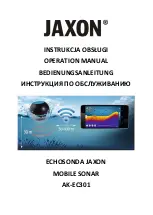
background image

BV-3100 Mobile Acoustic Underwater Vision® System

Part Number: 202679-01
©BlueView Technologies, Inc. All rights reserved.
All product names are trademarks of their respective companies.

Summary of Contents for BV-3100

Page 1: ...BV 3100 Mobile Acoustic Underwater Vision System Part Number 202679 01 BlueView Technologies Inc All rights reserved All product names are trademarks of their respective companies ...

Page 2: ...ed use is a violation of copyright laws Warning This product contains lead a chemical known to the state of California to causecancer birth defectsand other reproductiveharm Handling and or opening this unit may resultin exposuretolead in theformofsolder Warning Disassembly and repair of this electronic unit should only be performed by authorizedservicepersonnel Any modificationoftheserialnumberor...

Page 3: ...g a grounding wire with a grounding plug The plug must be plugged into an outlet that is properly installed and grounded DANGER Improper use of the grounding plug can result in a risk of electric shock If repair or replacement of the cord or plug is necessary do not connect the grounding wire to either flat blade terminal The wire with insulation having an outer surface that is green with or witho...

Page 4: ... Mounting 9 Installing the SPT Junction Box 10 Final Cable Connections 14 ProViewer Configuration 15 Pan Tilt Unit Operation 16 Positioning controls 16 Pre defined position buttons 16 Numeric tilt read out 16 Numeric pan readout 17 Target Depth selector 17 System Breakdown 17 Pole case 17 Chapter 4 Troubleshooting 18 Appendix A Technical Specifications 20 Appendix B Connector Pinouts 21 BV 3100 Us...

Page 5: ...luggage Standard Package Contents Please note that special orders may include variations to this list If you are not sure or feel your package may be missing items please contact BlueView at 206 545 7260 Component Sonar Module Hard Shell Transport Case Sonar Pan Tilt SPT Junction Box Pan and Tilt Pole with 50 ft Cable Assembly Transom Mount Assembly 7 ft Ethernet Cable Rugged USB Cable Power Cable...

Page 6: ... Pole Connectors BV 3100 User s Handbook 15 April 2009 Page 5 Main Pole Connector This connector provides power and data from the Sonar Pan Tilt Junction Box SPT to both the sonar and pan tilt Sonar Cable This connector provides power and data from the SPT to the sonar Pan and Tilt connector This connector provides power and control from the SPT to the pan tilt unit ...

Page 7: ...pan and tilt via a USB port The flash memory contains the necessary drivers for the USB to COM port converter The Ethernet port on the control box provides communication with the sonar The SPT box can handle input AC power between 110 and 240 volts BV 3100 User s Handbook 15 April 2009 Page 6 Ethernet Port to PC Sonar Communication AC Power Inlet Port 110 240 VAC To Sonar and Pan Tilt Unit USB Por...

Page 8: ...nect all required cabling 1 Remove the pole unit from shipping case 2 Place the top and bottom pole pieces end to end and pull the excess cable through the top of the pole 3 Rotate one of the pole segments till the alignment notches are adjacent to each other 4 Attach the lower section to the upper using the provided cap screws Insert the bolt first through the unthreaded upper flange and screw in...

Page 9: ... 2009 Page 8 NOTE The sonar is inserted into the clamp such that its connector is on the same side as the Pan Tilt connector NOTE Use the stickers and connector placement on the rear end cap of the sonar to determine the up down orientation of the sonar If the sonar is inverted be sure to select the inverted option in ProViewer s settings Inverted Head Alignment ...

Page 10: ...e into the clamp and close the clamp by tightening the threaded knob 3 Rotate the pole in the mount so that the sonar when set to the home position points in the desired direction BV 3100 User s Handbook 15 April 2009 Page 9 NOTE It is the user s responsibility to insure the pole mount is secured in a way that will support the pole assembly NOTE Do not let go of the pole assembly until the clamp i...

Page 11: ... for a USB Serial Port 1 Connect the USB port on the control box to an available USB port on the PC The Found New Hardware Wizard will guide you through the installation process BV 3100 User s Handbook 15 April 2009 Page 10 NOTE Do not close the second Found New Hardware Wizard window while installing the driver NOTE For Windows Vista disconnect your PC from the internet before installing drivers ...

Page 12: ...install Select No not this time and click Next 3 Select Install from a list or specific location and click Next 4 Click Browse and navigate to the flash drive Select the folder on that drive Click Next BV 3100 User s Handbook 15 April 2009 Page 11 ...

Page 13: ...plete the installation of the first driver 6 Next the USB Serial Porter Driver will be installed Select No not this time and click Next 7 Select Install from a list or specific location and click Next BV 3100 User s Handbook 15 April 2009 Page 12 ...

Page 14: ...flash drive Select the folder on that drive Click Next 9 The driver will install Click Finish to complete the installation of the second driver The PC is now ready to control the pan and tilt BV 3100 User s Handbook 15 April 2009 Page 13 ...

Page 15: ...ntrol box then to an available network connection port on the PC Verify that all connections in the diagram below have been made 2 Connect the power cable to the control box Connect the opposite end to a suitable AC power outlet All necessary connections have now been made BV 3100 User s Handbook 15 April 2009 Page 14 ...

Page 16: ...is properly indicated and then click Detect The software will automatically detect the Pan Tilt through the COM Port The ProViewer software is now properly configured BV 3100 User s Handbook 15 April 2009 Page 15 NOTE In some installations it may be necessary to manually assign a COM port in ProViewer The appropriate COM port to select can be found in Windows Device Manager Take note of the port U...

Page 17: ...me button will cause the pan tilt to automatically move to the home position The home position is factory set to 0 degrees pan and 0 degrees tilt You can specify the home position under the pan tilt section of the settings window under the file menu Clicking the stow button will cause the pan tilt to automatically move to the stow position The stow position is factory set to 0 degrees pan and 0 de...

Page 18: ... can tilt downwards positive tilt approximately 70 degrees Numeric pan readout 0 degrees is the center of movement The unit can pan clockwise positive rotation about 179 degrees The unit can pan counter clockwise negative rotation about 179 degrees Target Depth selector Selecting one of the target depths will cause the sonar start stop ranges and tilt angle to move to pre defined values BV 3100 Us...

Page 19: ...sconnected from the console rinse the pole and sonar with fresh water and return to their respective positions in the carrying case as shown BV 3100 User s Handbook 15 April 2009 Page 18 NOTE Care should be taken to ensure cables are positioned not to crimp or damage pole components or the cable while shutting the case ...

Page 20: ...ss Subnet Mask to 192 168 1 2 255 255 255 0 Sonar experienced a power glitch Unplug the AC power to the SPT Junction Box for 10 seconds and reconnect PC does not connect to Pan Tilt Unit P T Unit is not connected Verify the main pole cable is plugged into the SPT Junction Box Verify the sonar connector is attached to the sonar Verify the Ethernet cable is connected to the SPT Junction Box and the ...

Page 21: ...5 in Pole Length Collapsed 47 5 in Cable Length 50 ft Electrical Power Supply 110 240 VAC 100 W max Mechanical Pole case weight 52 lbs Pole case dimension 53 8 x 16 5 x 6 7 Recommended PC Specifications Processor 1 4 GHz Pentium M Memory 1GB DRAM Ports USB Ethernet Screen Sunlight Readable Screen BV 3100 User s Handbook 15 April 2009 Page 20 ...

Page 22: ... C N C 8 N C N C BV 3100 User s Handbook 15 April 2009 Page 21 8 Pin Connector to Sonar and Pan Tilt Unit Souriau UTG012 8S Pin Function A Ethernet RX to sonar B Ethernet RX to sonar C Ethernet TX to sonar D 24V DC E 24 DC Common F Ethernet TX to sonar G Data A to P T H Data B to P T 3 Pin C14 Power Connector Pin Function 1 110 240V AC 2 110 240V AC Ground 3 110 240V AC Common ...

Page 23: ...onar 4 24V DC 5 24V DC 6 Ethernet TX to sonar 7 Ground 8 Ground 9 N C 10 N C 4 Pin Connector to Pan Tilt Unit Impulse LPMIL 4 FS Pin Function 1 DC Common 2 24V DC 3 Data B 4 Data A 8 Pin Connector to Sonar and Pan Tilt Unit Souriau UTG612 8PN Pin Function A Ethernet RX to sonar B Ethernet RX to sonar C Ethernet TX to sonar D 24V DC E 24 DC Common F Ethernet TX to sonar G Data A to P T H Data B to ...

Page 24: ...BV 3100 User s Handbook 15 April 2009 Page 1 ...

Reviews: