INSTALLATION INSTRUCTIONS
URINAL SCREENS, BENCHES & SHOWER SEATS
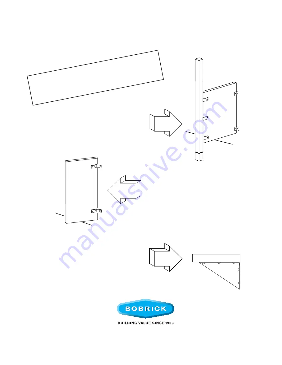
WALL
HUNG
BENCHES &
SHOWER SEATS
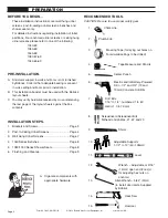
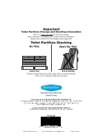
IMPOR
TANT:
Storag
e and Handling Inf
ormation on last pa
ge.
Review these instructions thor
oughly prior to
installation.
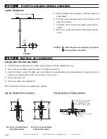
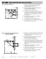
POST-TO
-CEILING
1033 Stainless Steel Edge
1043 High Pressure Laminate Edge
1083 Solid Phenolic
1183 Class A Solid Phenolic
1035 Stainless Steel Edge
1045 High Pressure Laminate Edge
1085 Solid Phenolic
1185 Class A Solid Phenolic
1545 Plastic Laminated Edge
1845 FRP
1040 High Pressure Laminate
1080 Solid Phenolic
1180 Class A Solid Phenolic