background image

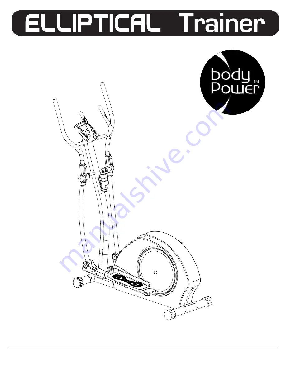
BR2710

OWNER’S MANUAL

* This item is for consumer use only and it is not meant for commercial use.

OWNER’S MANUAL

* This item is for consumer use only and it is not meant for commercial use.

Summary of Contents for BR2710

Page 1: ...BR2710 OWNER S MANUAL This item is for consumer use only and it is not meant for commercial use OWNER S MANUAL This item is for consumer use only and it is not meant for commercial use ...

Page 2: ...This page intentionally left blank ...

Page 3: ...g the assembly of your product or starting to exercise Please keep all children away from this item when in use Do not allow children to climb or play on them when they are not in use Supervise teenagers while they use this unit For your own safety always ensure that there is at least 3 feet of free space in all directions around your product while you are exercising Regularly check to see that al...

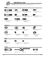
Page 4: ... Washer pre assembled Hardware List The following hardware is used to assemble your unit Please take a moment to familiarize yourself with these items PLEASE NOTE some of these parts may have already been pre assembled on your unit BR 2710 pre assembled ...

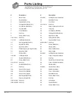
Page 5: ...ater Bottle Holder 16 Nylon Nut M8 45 Water Bottle 17 Washer M8 46L 46R Left Right Upper Handlebar 18L 18R Left Right Pedal 47 Foam of Upper Handlebar 19 Hex Bolt M8x45 mm 48 End Cap 20 Screw M4x20 mm 49 Steel Plate of Handle Pulse 21L L 21L R End Cap 50 Foam of Middle Handlebar 22 Hex Bolt M8x75 mm 51 Washer M6 23 End Cap 52a 52b Handle Pulse Wires 24a Sensor Wire Lower 53 Middle Handlebar 24b Se...

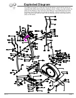
Page 6: ... the assembly process Please note that not all of the parts and hardware you see here will be used while you are assembling the machine because some of these items are already pre installed Please continue to the next page to begin the assembly process and use this page only as a reference guide for parts and hardware Exploded Diagram ...

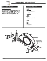
Page 7: ...ructions Hardware Required A s s e m b l y S t e p 1 Stabilizer Assembly Secure the Front Stabilizer 7 and Rear Stabilizer 2 to the Main Frame 1 by using four Carriage Bolts 4 four Arc Washers 5 and four Cap Nuts 6 BR 2710 ...

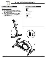
Page 8: ... y S t e p 2 Hardware Required Front Post Assembly A With the help of an assistant connect the Sensor Wire Lower 24a to the Sensor Wire Middle 24b B Secure the Front Post 31 to the Main Frame 1 by using four Bolts 30 and four Washers 17 BR 2710 ...

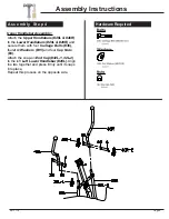
Page 9: ...Bolt 39 Repeat this process on the other side Pedal Arm Assembly The Plastic Spacer 15 and the Special Washer 59 are already pre assembled Ensure that they are properly in place as indicated in the assembly below Slide the Left Pedal Arm 11L into the Crank Stud and secure it with one Big Washer 13 and a Nylon Nut 14 as shown in the assembly below Repeat this process on the opposite side Before att...

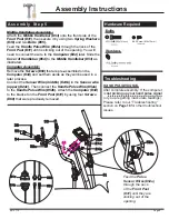
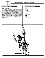
Page 10: ...lebars 46L 46R to the Lower Handlebars 29L 29R and secure them with four Carriage Bolts 36 four Arc Washers 35 and four Cap Nuts 6 Attach the snap on End Cap 32L 1 32L 2 to the left Left Lower Handlebar 29L Align the two together and press firmly until it snaps into place Repeat this process on the opposite side BR 2710 ...

Page 11: ...pre assembled on the Computer 34 and set them aside as they will be used in a later process Connect the Sensor Wire middle 24b to the Sensor wire upper 24c Then connect the Handle Pulse Wire 52a to the Handle Pulse Wire 52b Attach the Computer 34 to the bracket on the Front Post 31 by using four Screws 60 that were previously removed After complete assembly If the computer is not picking up your h...

Page 12: ...ion as shown To better fit the way you exercise you can customize the pedal to any of the 3 available positions that gives you most comfortable distance to grip the handlebars Assemble the End Caps 10L 1 10L 2 to the rear of the Left Pedal Arm 11L with three Screws 9 Repeat this process on the opposite side Assemble the End Caps 21L L 21L R to the front of the Left Pedal Arm 11L with two Screws 20...

Page 13: ...Water Bottle Holder 44 have already been pre installed onto the Front Post 31 Remove the two Screws 41 and two Washers 42 located on the Front Post 31 as illustrated Then secure the Water Bottle Holder 44 to the Front Post 31 using the two Screws 41 and two Washers 42 that were just removed Slide the Water Bottle 45 into place BR 2710 ...

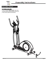
Page 14: ...Page 12 Assembly Instructions A s s e m b l y S t e p 8 AC Adapter Assembly Plug in the AC Adapter 58 male plug into the female socket located at the rear of the unit as shown by the arrow BR 2710 ...

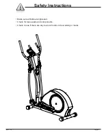
Page 15: ...Safety Instructions Make sure all bolts are tightened Check for loose parts and components Check to see if there are any tears or bends in the welding or metal Page 13 BR 2710 ...

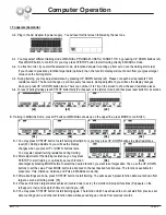
Page 16: ...ows up on the upper line press MODE to confirm b1 b1 M M M M b2 b3 b4 B 1 You may press ST STOP button to start training directly b2 or you may press UP DOWN buttons to adjust resistance level b3 During adjustment you will see the display changes when you press UP or DOWN buttons twice You may also adjust training resistance during training B 2 After adjustment of the training resistance you may p...

Page 17: ...achieved to zero will start from previous set data counting down and other set function data will keep counting up or down from previous records C 7 During all training period you may press ST STOP to stop monitor counting at anytime D Training in USER mode press UP button until USER shows up on the upper line press MODE to confirm d1 In USER mode you can set your own desired training program d1 d...

Page 18: ...esistance will be adjusted automatically depends on your current heart beat If your heart beat is very high compare to the preset target the training resistance will decrease immediately one level and keep decreasing one level every 15 seconds by monitoring your current heart beat change If the training resistance has dropped to level one but your heart beat is still high the monitor will stop all...

Page 19: ...en training in Manual Program or User mode the monitor will beep when your current heart rate reaches the preset target To select Target Heart Rate training mode for training please refer to the above Training in Target Heart Rate mode To ensure the heart rate readout is stable please hold the handgrip sensors with both hands during training RECOVERY After exercising for a period of time keep hold...

Page 20: ...following 1 Check to ensure all computer sensor wires are properly connected and are not damaged You may need to refer to installation assembly directions for the sensor wires in this manual If the computer display is blank not displaying any data or does not appear to power on please adjust the following 1 Check to ensure all sensor wires are all properly connected and are not damaged 2 Check to ...

Page 21: ...longside your left knee 2 Place your left arm on the outside of your right leg and pull against that leg while twisting your trunk as far as possible to the right Place your right hand on the floor behind your buttocks Reverse leg posi tions and repeat Hip Stretch 1 Lie on your back and raise your right leg as you clasp both hands under the back of the knee Keep your left leg straight 2 Gently pull...

Page 22: ...houlder to the upper back 2 Try to reach your finger tips If you are not able to reach your fingertips use a towel as an extension of your hands and gently pull one hand toward the other Reverse arm positions and repeat Calf Stretch 1 Place both hands against a wall to aid your balance Press the ball of your left foot against the wall and keep the heel of the same foot rested on the floor make sure y...

Page 23: ...Proof of purchase Model Number BR 2710 BR 2710 version 3 31 2011 ...

Page 24: ...Body Flex Sports Inc 21717 Ferrero Parkway Walnut CA 91789 Telephone 888 266 6789 Email info bodyflexsports com ...

Reviews: