background image

Before use the product, please read this manual carefully.

DR-

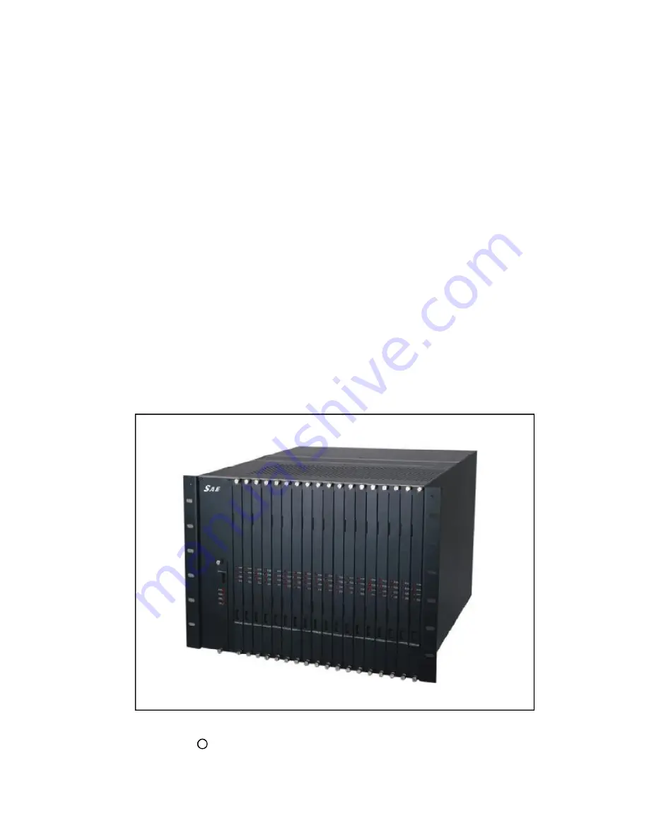
8000 Video Switching Matrix

Installation Manual

Summary of Contents for DR-8000

Page 1: ...Before use the product please read this manual carefully DR 8000 Video Switching Matrix Installation Manual ...

Page 2: ...tallation 7 6 1 DR 8000 matrix structure 7 6 2 Mother board 9 6 3 Power supply module 11 6 4 Control board 13 6 5 Control output connection board 16 6 6 Video input switching board 17 6 7 Video input connection board 20 6 8 Video output character screen overlay board 21 6 9 Video output connection board 24 7 DR 8000 matrix system 25 7 1 DR 8000 matrix system s camera connection 25 7 2 DR 8000 matr...

Page 3: ...edance DR 8000 consists of power supply module central control module data receiving buffer module VIM video input module VOM video output module and their corresponding back boards DR 8000 could work independently or expand up to 4 bays when lager volume is needed In addition to video switching function DR 8000 can link to various accessories like alarm input box alarm output box multi function k...

Page 4: ...l Output Signal 2V Peak to Peak Output Impedance 75 Ω l Output Impedance 75 Ω l Insert Gain 0 5dB l S N Ratio Weighted 52 dB l Adjacent Channel Isolation Degree Input to Input 50 dB l Adjacent Channel Crosstalk Input to Output 40 dB l Frequency Characteristics 3dB Bandwidth 50Hz 12MHz l DC Voltage Video Signal About 0 4V 0 6V l KB Receiver Controlling Time 20ms Typical l Switch Complete switching ...

Page 5: ...ck n Modules functions description l Mother board It has 18 standard slots and 2 special slots Standard slots are for Video input switching boar Video input connection board Video output character screen overlay board and Video output connec tion board each board has its own unique ID It can accept 1 17 video input modules 16 272 channels 1 4 video output modules 16 64 channels Special slots are f...

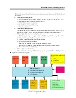
Page 6: ...rlay function d 16X64 full cross matrix switching input bus 64 channels select 16 channel according slot ID output bus 16 channels Output standard video signal with character overlay e Module ID and function DIP setting l Video output connection board This module has 16 video input BNC jacks surge proof grade 1 500V and EMI protection n System schematic figure Picture 2 System schematic figure Vid...

Page 7: ...rresponding board Single bay configuration is shown below Table 1 Single bay configuration n Two bays configuration Two DR 8000 bays system has 2 power supply 1 pair special slots 36 pairs standard slots User can use any pair of standard slots but please make sure each board is with its corresponding board Each bay needs an expansion module Two bays configuration is shown below Table 2 Two bays co...

Page 8: ...stallation 7 6 1 DR 8000 matrix structure 7 6 2 Mother board 9 6 3 Power supply module 11 6 4 Control board 13 6 5 Control output connection board 16 6 6 Video input switching board 17 6 7 Video input connection board 20 6 8 Video output character screen overlay board 21 6 9 Video output connection board 24 7 DR 8000 matrix system 25 7 1 DR 8000 matrix system s camera connection 25 7 2 DR 8000 mat...

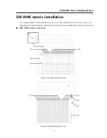
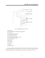
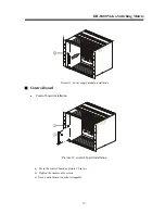
Page 9: ...ded to install DR 8000 matrix in 19 inch standard rack Please do not leave any thing block the ventilation holes otherwise the matrix may become malfunctioned because of overheat n DR 8000 matrix structure Picture 3 DR 8000 matrix front view Picture 4 DR 8000 matrix back view ...

Page 10: ... character screen overlay board 08 Video output connection board 09 Power input jack 10 Power wires 11 Power switch 12 Power socket 13 Front cover 14 Back cover 15 Connection bridge Every board should be installed through the slot and connect to the mother board and the correspond ing board should be installed at the opposite side refer to blow table to find out boards and their corre sponding boa...

Page 11: ...18 standard slots and 2 special slots Standard slots are for Video input switching boar Video input connection board Video output character screen overlay board and Video output connection board each board has its own unique ID It can accept 1 17 video input modules 16 272 channels 1 4 video output modules 16 64 channels Special slots are for Control board and Control output connection board There...

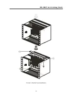
Page 12: ...DR 8000 Video Switching Matrix 10 Picture 6 Mother board installation 15 15 1 ...

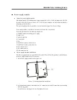
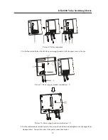
Page 13: ...components 1 Standard industrial switching power supply 2 upper cover 3 power supply box 4 transformer 5 fan 6 transformer primary connection wire 7 transformer secondary connection wire 8 AC connection wire 9 DC connection wire 10 fan connection wire l Power supply module installation The Power supply module was preinstalled in the matrix Please follow the procedure to install remove the Power su...

Page 14: ... module with the upper cover to the box Picture 9 Power supply module installation 1 Picture 10 Power supply module installation 2 4 Put the whole module into the matrix at the arrow showed direction and tighten it on the upper lower aluminum bars Connect the wires to the power connection socket 1 4 7 6 8 9 3 5 10 2 ...

Page 15: ...1 Power supply module installation n Control board l Control board installation Picture 12 control board installation a Put in the control board as picture 12 shows b Tighten the irremovable screws c Note control board is not hot swappable 2 2 3 ...

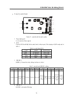
Page 16: ... below Table7 control board DIP SW1 setting 4 DIP SW2 DIP SW2 is for matrix ID setting O N 1 2 O N 1 2 1 2 3 4 5 6 7 Label remark Normal status POW 5V indicator Always light POW 5V indicator Always light COD sending Blink STA status Blink BIT 3 BIT 4 BIT 5 OFF ON OFF ON OFF OFF OFF OFF ON OFF ON OFF ON BIT 6 BIT 7 BIT 2 Reserved working mode Initial ate Reserved Reserved BIT 8 Chinese English Disp...

Page 17: ...atrix ID is 10 ON OFF ON OFF ON Matrix ID is 11 ON OFF ON OFF OFF Matrix ID is 12 ON OFF OFF ON ON Matrix ID is 13 ON OFF OFF ON OFF Matrix ID is 14 ON OFF OFF OFF ON Matrix ID is 15 ON OFF OFF OFF OFF Matrix ID is 16 OFF ON ON ON ON Matrix ID is 17 OFF ON ON ON OFF Matrix ID is 18 OFF ON ON OFF ON Matrix ID is 19 OFF ON ON OFF OFF Matrix ID is 20 OFF ON OFF ON ON Matrix ID is 21 OFF ON OFF ON OFF...

Page 18: ...board is not hot swappable l Notes for Control output connection board Picture 15 Control output connection board schematic picture 1 system internal video BNC This is matrix special setting menu output BNC jack It can connect to monitor or loop to matrix output 2 RS232 Port It is a standard serial port for computer to download upload system data 3 RJ45 Port LAN This is a standard Ethernet port th...

Page 19: ...ard as picture 16 shows b Tighten the irremovable screws c Note Video input switching board is hot swappable l Notes for Video input switching board Picture 17 Video input switching board schematic picture This board is for switching camera video signal User can adjust syn signal for each video channel via system menu or management software 5 O N 1 2 5 1 2 3 4 BIT1 BIT2 BIT3 BIT4 BIT5 BIT6 BIT7 ...

Page 20: ...ON OFF OFF ON ON 15 225 240 ON OFF OFF OFF ON ON 16 241 256 OFF OFF OFF OFF ON ON 17 257 272 ON ON ON ON OFF ON 18 273 288 OFF ON ON ON OFF ON 19 289 304 ON OFF ON ON OFF ON 20 305 320 OFF OFF ON ON OFF ON 21 321 336 ON ON OFF ON OFF ON 22 337 352 OFF ON OFF ON OFF ON 23 353 368 ON OFF OFF ON OFF ON 24 369 384 OFF OFF OFF ON OFF ON 25 385 400 ON ON ON OFF OFF ON 26 401 416 OFF ON ON OFF OFF ON 27 ...

Page 21: ... ON OFF 45 705 720 ON ON OFF OFF ON OFF 46 721 736 OFF ON OFF OFF ON OFF 47 737 752 ON OFF OFF OFF ON OFF 48 753 768 OFF OFF OFF OFF ON OFF 49 769 784 ON ON ON ON OFF OFF 50 785 800 OFF ON ON ON OFF OFF 51 801 816 ON OFF ON ON OFF OFF 52 817 832 OFF OFF ON ON OFF OFF 53 833 848 ON ON OFF ON OFF OFF 54 849 864 OFF ON OFF ON OFF OFF 55 865 880 ON OFF OFF ON OFF OFF 56 881 896 OFF OFF OFF ON OFF OFF ...

Page 22: ... as picture 18 shows b Tighten the irremovable screws c Note Video input connection board is hot swappable l Notes for Video input connection board Picture 19 Video input connection board schematic picture 1 DIP SW4 It sets the 75 Ω resistor ON connect 75 Ω resistor OFF disconnect 2 DIP SW3 It sets the 75 Ω resistor ON connect 75 Ω resistor OFF disconnect 6 1 2 3 4 5 6 7 8 9 1 0 1 1 1 2 1 3 1 4 1 ...

Page 23: ... board is hot swappable 6 8 2 Notes for Video output character screen overlay board Picture 21 Video output character screen overlay board schematic picture 7 O N 1 2 1 2 3 4 5 6 7 8 0 6 O N 1 2 3 4 5 6 7 8 0 6 O N 1 2 3 4 5 6 7 8 0 6 ON 1 2 3 4 5 6 7 8 0 6 ON SW 4 SW 8 SW 6 SW 10 1 2 3 4 5 1 2 3 4 5 6 7 8 0 6 O N 1 2 3 4 5 6 7 8 0 6 O N 1 2 3 4 5 6 7 8 0 6 O N 1 2 3 4 5 6 7 8 0 6 O N SW3 SW7 SW5 ...

Page 24: ...ED 4 Programming port It is for board software update 5 DIP RP1 It sets internal RS485 terminal 120 Ω resistor ON connect 120 Ω resistor OFF disconnect 6 DIPs This group of DIPs is for 16 channels video switching setting please set them strictly according its ID otherwise it will cause mass switching BIT1 BIT2 BIT3 remark BIT4 BIT5 BIT6 BIT7 BIT5 OFF OFF OFF Normal status ON ON Big font ON OFF Sma...

Page 25: ...10 OFF ON OFF ON OFF ON OFF ON SW3 OFF OFF OFF OFF OFF OFF OFF OFF SW5 OFF OFF OFF OFF OFF OFF OFF OFF SW7 OFF OFF OFF OFF OFF OFF OFF OFF SW9 OFF OFF OFF OFF OFF OFF OFF OFF 1 3 DIP BIT1 BIT2 BIT3 BIT4 BIT5 BIT6 BIT7 BIT8 Board ID SW3 ON OFF ON OFF ON OFF ON OFF SW5 ON OFF ON OFF ON OFF ON OFF SW7 ON OFF ON OFF ON OFF ON OFF SW9 ON OFF ON OFF ON OFF ON OFF SW4 OFF OFF OFF OFF OFF OFF OFF OFF SW6 ...

Page 26: ...o output connection board installation a Put in the Video output connection board as picture 22 shows b Tighten the irremovable screws c Note Video output connection board is hot swappable l Notes for Video output connection board Picture 23 Video output connection board schematic picture 8 1 2 3 4 5 6 7 8 9 10 11 12 13 14 16 ...

Page 27: ...onnection Use coaxial video cable to connect the camera to BNC 1 16 of video input switching board marked IN on the top The distance between camera and matrix should be less than 200 350 meters Every video switching board has two 34pin video looping socket Note Video Coaxial Cable Video Coaxial Cable Video Coaxial Cable ...

Page 28: ...Picture 25 Monitor connection Use coaxial video cable to connect the monitor to BNC 1 16 of video input switching board marked OUT on the top The distance between monitor and matrix should be less than 200 350 meters Note Video Coaxial Cable Video Coaxial Cable Video Coaxial Cable ...

Page 29: ...DR 8000 Video Switching Matrix 27 n DR 8000 single bay matrix system application Picture 26 DR 8000 single bay matrix system application ...

Page 30: ...t 32 Channals Digital Video In HUB Monitor 1 32 Digital Video Signal Analog Video Signal Communication Signal RS485 Signal Alarm Input Signal Alarm Output Signal Matrix 1 1024 KB06 1 64 AO16 1 4 AI64 1 16 CD64 1 4 Analog System Digital System 1 64 1 1024 PC 1 64 32 Channals Out Internet 32 Channals In HUB Monitor 1 32 Video Signal Communication Signal RS485 Signal Alarm Input Signal Alarm Output S...

Reviews: