BOMBARDIER Primus 2000XP, Pilot Training Manual
The BOMBARDIER Primus 2000XP Pilot Training Manual is a comprehensive guide for pilots operating this advanced avionics system. This manual covers all aspects of the Primus 2000XP, from system setup to in-flight operations. Download your free copy of this manual from 88.208.23.73:8080 today to enhance your training and proficiency.
Share
Download
Reviews:
No comments
Related manuals for Primus 2000XP

G1000 Diamond DA62
Brand: Garmin Pages: 630
Apollo GX55
Brand: II Morrow Pages: 177
Beacon Sign
Brand: Data Display Pages: 40

7450 2E
Brand: Bartscher Pages: 22

Epic Eagle
Brand: EPIC OPTIX Pages: 2

Dreamoc Diamond
Brand: Realfiction Pages: 8
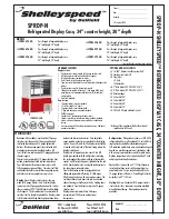
Shelleyspeed SPRD36P-36N
Brand: Delfield Pages: 2
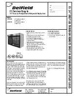
F5SR48N
Brand: Delfield Pages: 2

G3X Touch
Brand: Garmin Pages: 68

ONRB
Brand: Hill Phoenix Pages: 44

806-005
Brand: COBHAM Pages: 16
KG 71EXP
Brand: BENDIXKing Pages: 280

TSID-72-3
Brand: True Pages: 2


