background image

Summary of Contents for Super-Mod 1981

Page 1: ......

Page 2: ...n purchased for racing only this manual has been prepared to acquaint the owner operator with the various vehicle controls and owner re lated maintenance instructions This manual emphasizes particular...

Page 3: ...ols or foreign ob jects are left in the engine compartment Your snowmobile is not designed to be driven or operated on black top bare earth or other abrasive surfaces On such surfaces abnormal and exc...

Page 4: ...sion drive pulley countershaft 9 MAINTENANCE PROCEDURES Pulley guard removal drive belt removal drive belt con dition drive belt tension drive pulley drive chain ten sion track condition track adjustm...

Page 5: ...disc brake system binding the vehi cle to a fast smooth stop C Tether Cut Out Switch A pull switch located on the right side of steering sup port tube Attach tether cord to wrist or other convenient l...

Page 6: ...io results in serious engine damage Recommended fuel oil ratio is 20 1 Imperial Measures 2 cans of 16 oz Blizzard oil to 4 Imp gals 20 to 1 U S Measures 2 cans of 12 oz Blizzard oil to 4 U S gals 20 t...

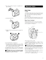
Page 7: ...turn to idle position when released Skis and track Check that the skis and the track are not frozen to the ground or snow surface and that steering operates free ly Brake System Condition Check brake...

Page 8: ...PROCEDURE 1 Test operation of throttle control lever 2 Engage choke by depressing each lever To disen gage choke simply lift the levers The chokes should always be used for easier cold engine starts A...

Page 9: ...m condition 6 Brake system bleeding 12 Rotary valve oil level 10 Chaincase oil level 10 Drive belt condition 12 Pulley alignement and drive belt tension 12 Drive pulley 13 Drive chain tension 17 Track...

Page 10: ...lly obtained on other com ponents systems not covered in this manual Unless ogherwise specified engine should be tuned OFF for all lubrication and maintenance procedures Recommended Lubricants For Sup...

Page 11: ...pressure Once obtained hold lever open bleeder valve then quickly depress brake lever Close bleeder valve and allow brake lever to return slowly Continue pressing and releasing brake lever until the...

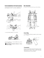
Page 12: ...at with grease CAUTION Do not lubricate throttle and or brake cable housings Rear Suspension Lubricate all cross shafts and sleeves with anti seize Drive Pulley All moving parts and friction surfaces...

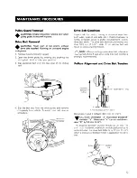
Page 13: ...The drive belt width should not be less than 33 3 mm 1 5 16 wide A too narrow belt will result in a loss of performance O NOTE When installing a new drive belt a break in period of 4 or 5 laps at no...

Page 14: ...at the pulley width between each halves is the same all around Using shims adjust the driven pulley in order to have a free play of 0 5 mm 020 on each side Drive Pulley Drive pulley is assembled with...

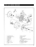
Page 15: ...Locking ring 5 Pivot pin kit 6 Cam arm kit 7 Spacer 8 Spider 9 Allen set screw 10 Pin 11 Steel thrust washer 12 Roller 73 Fiber thrust washer 14 Wear button kit 15 Spring 16 Cover 17 Steel cover with...

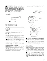
Page 16: ...procedure IMPORTANT Before disassembling the drive pulley all components should be marked for proper assembly ONOTE The drive pulley spring can be replaced without removing the drive pulley from the...

Page 17: ...on surfaces with a dry lubricant PIN 414 3815 00 Pulley Installation CAUTION Prior to installation clean the crank shaft taper with fine steel wool and acetone Dry with a clean dry cloth Lock the cran...

Page 18: ...particles which could be thrown out while track is rotating Keep hands tools feet and clothing clear of track Ensure rio one is stan ding in close proximity to the vehicle Lift rear of the vehicle an...

Page 19: ...ys ensure to maintain the ski stance of 105 4 cm 41 1 2 while performing this adjust ment To adjust the camber Loosen the lock nuts of the upper and lower front arms Turn the arms manually until recom...

Page 20: ...sorber top retaining nut Screw or unscrew the lower nut to adjust the frame height to the rider s preference Measure the distance from the ground to the top of the stabilizer bar arm on both sides to...

Page 21: ...ball joints ski coupler bolts etc If necessary replace or retighten Check condition of skis and ski runners Replace if worn Steering Adjustment Prior to any suspension and or steering adjustment alwa...

Page 22: ...re that the steering transfer shaft ball joint attach ment brackets are vertical and that the skis are pointed directly forward Loosen the lock nuts of each tie rod Equally turn the tie rods manually...

Page 23: ...ower the bypass hose to drain engine To refill the cooling system Close the radiator drain valve open the bleeder screw pour in the liquid until it reaches the bleeder close the bleeder screw Bleeder...

Page 24: ...to specification S Throttle slide adjustment WARNING Ensure the engine is turned OFF prior to the throttle slide adjustment With the throttle cable adjuster jam nut unlocked press the throttle lever a...

Page 25: ...t 1 Position of the armature plate 2 Position of the timing marks on magneto ring 3 Air gap between trigger coil and magneto ring 4 Timing verification using a stroboscopic timing light 1 To obtain be...

Page 26: ...000 R P M Magneto ring mark If necessary to adjust unscrew slightly the two 2 screws holding trigger coil bracket then move brack et up or down If correct timing is impossible with trigger coil brack...

Page 27: ...iming of rotaty valve No spark at plug a fouled or wet plug b faulty CD box c faulty generating coil d open or short circuit in armature plate e faulty spark plug protector f shorted tether switch Bad...

Page 28: ...m Engine operation is erratic at high speed Spark plugs are improperly gapped dirty or faulty Crankcase compression leaks Incorrect carburetor float level Broken or cracked tuned exhaust Short circuit...

Page 29: ...o low Weak or broken spring Wrong belt installed Incorrect counterweights installed Engagement speed too high Incorrect spring Hollertsl worn Incorrect counterweights installed Erratic engagement Roll...

Page 30: ...m with the recommended solution 60 antifreeze 40 water To refill the cooling system Close the radiator drain valve open the bleeder screw pour in the liquid until it reaches the bleeder Close the blee...

Page 31: ...gs at grease fittings Check condition of skis and ski runners Replace if worn Slider Shoe Lubricant Tank Check hoses for signs of leakage Also check tightness of fittings on slide check valve and tank...

Page 32: ...alcohol Do not use strong soaps degreasing solvents abrasive cleaners paint thinners etc Inspect hood and repair damage Repair kits are avail able at your authorized dealer Clean frame Use only tI Alu...

Page 33: ...2 Bore 59 5 mm Stroke 61 mm Displacement 339 2 cm3 Compression ratio 5 15 5 1 Squish area 1 2 mm 047 Squish angle 14 Rotary valve opening B T D C 1370 closing A T D C 65 Cylinder port timing Transfer...

Page 34: ...4 mm Idle outlet diameter 0 7 mm Valve seat diameter 1 5 mm Starter jet diameter 1 5 mm Idling R P M 3000 3500 Gasoline Aviation type light blue 100 LL octane Light green 100 to 130 octane Oil Blizza...

Page 35: ...ey spring preload 131bs Driven pulley cam pitch lead 10 9 8 Pulley center to center distance 26 8 cm 109 16 1 Offset dimension nominal X Y 34 1 mm 11 11 32 Belt number Bomb PIN 414375800 Dayco Max PIN...

Page 36: ...resistance Generating coil resistance Low High Trigger coil resistance Trigger coil gap with mag ring Electronic advance box Voltage regulator Fuse tacho TORQUE REACTION 145lbs in 135 Ibs in 25lbs in...

Page 37: ......

Reviews: