background image

Bosch

 Buderus SSB Boiler Control Operations

SSB800SA | SSB1000SA | SSB1000TL  

Control Operations Guide 

WARNING:

the heating system can cause personal injury and property damage.

Follow these instructions precisely.

If you require assistance or further information, contact a licensed 

Summary of Contents for Buderus SSB

Page 1: ...rations SSB800SA SSB1000SA SSB1000TL Control Operations Guide WARNING the heating system can cause personal injury and property damage Follow these instructions precisely If you require assistance or further information contact a licensed ...

Page 2: ...2 Bosch Buderus SSB800SA SSB1000SA SSB1000TL Boilers Control Operations Guide 01 2020 Bosch Thermotechnology Corp Data subject to change ...

Page 3: ... 4 1 2 Safety 4 2 Boiler Parameters 5 3 Module Cascade Settings 7 4 Boiler Cascade Settings 8 5 Heating Modes 9 5 1 Central Heating CH Mode 9 5 1 1 Central Heating Mode 0 9 5 1 2 Central Heating Mode 1 10 5 1 3 Central Heating Mode 2 11 5 1 4 Central Heating Mode 3 12 5 1 5 Central Heating Mode 4 13 6 Domestic Hot Water 14 6 1 Domestic Hot Water Operation 14 7 Boiler Cascade Settings 15 7 1 Cascad...

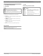
Page 4: ... avoided will result in death or serious injury WARNING indicates a hazardous situation which if not avoided could result in death or serious injury CAUTION indicates a hazardous situation which if not avoided could result in minor to moderate injury NOTICE is used to address practices not related to personal injury Important information This symbol indicates important information where there is n...

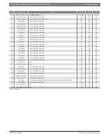
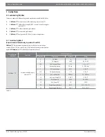
Page 5: ... F 32 F 86 F 23 Design Supply Min Limit The minimum supply water temperature the heating system will provide to the system 86 F 39 2 F 179 6 F 24 Design Supply Max Limit The maximum supply water temperature the heating system will provide to the system 194 F 80 6 F 194 F 25 Warm Weather Shut Dn The temperature above which heating is no longer necessary All calls for heat will be ignored as long as...

Page 6: ... N A N A 123 Prog Input 8 Factory Setting Do Not Change N A N A N A 124 Prog Input RT Factory Setting Do Not Change N A N A N A 125 Prog Output 1 Factory Setting Do Not Change N A N A N A 126 Prog Output 2 Factory Setting Do Not Change N A N A N A 127 Prog Output 3 Factory Setting Do Not Change N A N A N A 128 Prog Output 4 Factory Setting Do Not Change N A N A N A 129 Flow Sensor Factory Setting ...

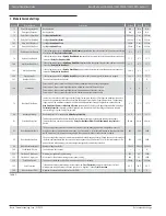
Page 7: ...rate at temperatures greater than or less than the desired Target System Supply Temperature The operating range in which the modules are allowed to adjust the individual module supply temperatures is defined by the Max Setp Offset Down and Max Setp Offset Up parameter 80 values Each dependent module will display a Calculated Setpoint temperature on the display which will be within this Off set Ran...

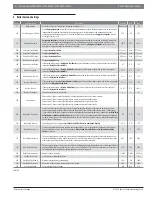
Page 8: ... Quick Stop Next 14 4 F 0 F 108 F 167 Number Of Boilers The amount of boilers in the cascade 1 1 8 168 Power Mode Power mode 0 Power control disabled each boiler modulates based on the system setpoint Power mode 1 Power control algorithm to have a minimum amount of boilers active Power mode 2 Power control algorithm to have a maximum amount of boilers active Power mode 3 Power control algorithm to...

Page 9: ...the boiler using dry contacts 9 and 10 CH Mode 0 Boiler demand is generated thru a call for heat on low voltage contacts 9 and 10 dry contacts only The Boiler will then target a temperature equal to CH Setpoint par 3 at the Supply Temperature Sensor CentralHeating CH Mode Description Set these Parameters Parameter Description Default Range CH Mode 0 Setpoint control using dry contacts TT 1 CH Mode...

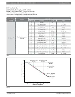
Page 10: ...F 1 8 1 8 F 5 Boiler Pump Overrun 30 sec 0 900 sec 7 CH Hysteresis Up 36 F 0 36 F 112 CH Hysteresis Down 9 F 0 36 F 9 Anti cycle Period 180 sec 10 900 sec 10 Anti cycle Temp Diff 28 8 F 0 36 F 14 Max Power CH 100 50 100 15 Min Power CH 1 1 30 19 Design Supply Temp 194 F 86 194 F 20 Design Outdoor Temp 23 F 13 77 F 21 Baseline Supply Temp 104 F 68 194 F 22 Baseline Outdoor Temp 68 F 32 86 F 23 Desi...

Page 11: ... contacts are open using a clock or switch CentralHeating CH Mode Description Set these Parameters Parameter Description Default Range CH Mode 2 Full Outdoor reset with no heat demand 1 CH Mode 0 0 5 109 Calc Set point Offset 0 F 1 8 1 8 F 5 Boiler pump overrun 30 sec 0 900 sec 7 CH Hysteresis Up 36 F 0 36 F 112 CH Hysteresis Down 9 F 0 36 F 9 Anti cycle Period 180 sec 10 900 sec 10 Anti cycle Tem...

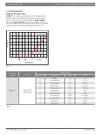
Page 12: ...ed to the curve when 9 and 10 contacts are open using a clock or switch CentralHeating CH Mode Description Set these Parameters Parameter Description Default Range CH Mode 3 Permanent Setpoint Demand 1 CH Mode 0 0 5 3 CH Setpoint 140 F 86 194 F 109 Calc Set point Offset 0 F 1 8 1 8 F 5 Boiler pump overrun 30 sec 0 900 sec 7 CH Hysteresis up 36 F 0 36 F 112 CH Hysteresis down 9 F 0 36 F 9 Anti cycl...

Page 13: ...curred The Boiler and CH pump contacts will remain energized as long as the voltage from the BMS remains greater than 1 VDC Figure 2 OFF 1 0 1 5 2 0 ON 9 Modulation CH Setpoint Max CH Setpoint Min Voltage Vdc Set Point F CentralHeating CH Mode Description Set these Parameters Parameter Description Default Range CH Mode 4 Analog 0 10 VDC Setpoint Control 1 CH Mode 0 0 5 109 Calc Setpoint Offset 0 F...

Page 14: ...ter temperature falls DHW Tank Hyst Down degrees below the desired set temperature for hot water the boiler will begin to heat the indirect tank with a setpoint of DHW Tank Setpoint plus DHW Tank Supply Extra The system will stop heating the tank when it reaches DHW Tank Setpoint plus DHW Tank Hyst Up Using a field supplied aquastat 1 Wire your field supplied aquastat to 7 and 8 on low voltage ter...

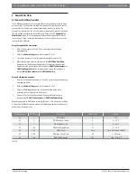
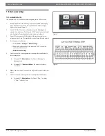
Page 15: ...ntrol board 3 Using 18 2 wire connect all of the boilers in the cascade using the low voltage contacts 1 and 2 on each boilers control board Note the polarity 4 Turn the power on to all boilers a Press Menu Settings Boiler Settings b Using the Arrow Key pad enter the passcode 0300 to enter the service level of the control c Boiler Cascade Settings 5 Scroll to each of the following parameters and a...

Page 16: ...United States and Canada Bosch Thermotechnology Corp 65 Grove Street Watertown MA 02472 Tel 866 642 3198 Fax 954 776 5529 www boschheatingandcooling com BTC 438002103 A 01 2020 ...

Reviews: