background image

Bosch Security Systems | 2003-11 

Eazeo DVR

 | Installation Manual | Table of Contents

EN

 | 3

1.

SAFETY PRECAUTIONS ......................................................................................................................................................... 5

1.1

IMPORTANT SAFEGUARDS .......................................................................................................................5

1.2

FCC INFORMATION  ......................................................................................................................................6

2.

INTRODUCTION  ......................................................................................................................................................................... 6

2.1

FEATURES ........................................................................................................................................................6

2.2

FRONT PANEL  ................................................................................................................................................7

2.3

REAR PANEL  ...................................................................................................................................................8

2.3.1 Power .....................................................................................................................................................8

2.3.2 Eazeo Observation Unit .....................................................................................................................8

2.3.3 RS232 serial connector  ....................................................................................................................8

2.3.4 IR remote control eye connector  .....................................................................................................8

2.3.5 LAN connector  ....................................................................................................................................8

2.3.6 Alarm connections  ..............................................................................................................................9

2.4

REMOTE CONTROL UNIT  ...........................................................................................................................9

3.

OPERATION  ............................................................................................................................................................................... 10

3.1

INSTANT RECORDING .............................................................................................................................. 10

3.2

ALARM RECORDING ................................................................................................................................. 10

3.2.1 Pre-alarm recording  ......................................................................................................................... 10

3.3

NORMAL PLAYBACK ................................................................................................................................. 10

3.4

SEARCH PLAYBACK  ................................................................................................................................. 10

3.5

COPY  .............................................................................................................................................................. 11

3.5.1 Still image copy  ................................................................................................................................ 11

3.5.2 Copy to movie file  ............................................................................................................................ 11

3.6

SECURITY LOCK SETTING  ..................................................................................................................... 11

4.

MENU SET-UP .......................................................................................................................................................................... 12

4.1

MAIN MENU ................................................................................................................................................... 12

4.2

CLOCK/LANGUAGE MENU ..................................................................................................................... 12

4.3

NORMAL RECORD MENU  ....................................................................................................................... 12

4.4

ALARM RECORD MENU  ........................................................................................................................... 12

4.5

TIMER MENU ................................................................................................................................................. 13

4.6

BUZZER MENU  ............................................................................................................................................ 14

4.7

ARCHIVE MENU ........................................................................................................................................... 14

4.8

NETWORK MENU  ....................................................................................................................................... 14

4.9

SYSTEM SETTING MENU ......................................................................................................................... 15

4.10

PASSWORD MENU .................................................................................................................................... 15

EazeoRecorderInstal.book  Page 3  Wednesday, March 3, 2004  12:23 PM

Summary of Contents for Eazeo

Page 1: ...3 5 LAN connector 8 2 3 6 Alarm connections 9 2 4 REMOTE CONTROL UNIT 9 3 OPERATION 10 3 1 INSTANT RECORDING 10 3 2 ALARM RECORDING 10 3 2 1 Pre alarm recording 10 3 3 NORMAL PLAYBACK 10 3 4 SEARCH PLAYBACK 10 3 5 COPY 11 3 5 1 Still image copy 11 3 5 2 Copy to movie file 11 3 6 SECURITY LOCK SETTING 11 4 MENU SET UP 12 4 1 MAIN MENU 12 4 2 CLOCK LANGUAGE MENU 12 4 3 NORMAL RECORD MENU 12 4 4 ALAR...

Page 2: ...TIONS 18 6 1 RS 232 INTERFACE 18 6 1 1 RS 232 control protocol 18 6 2 RECORDING TIME 19 6 3 TECHNICAL SPECIFICATIONS 20 Display abbreviations II Pause A REC Alarm record BASIC Basic quality HIGH High quality LOW Low quality LOWER Lowest quality MENU Menu PAUSE Pause P END Pause end PLAY Play P END Play end P RPT Play repeat REC Record SRCH Search STDRD Standard quality SUPER Superior quality SYSLD...

Page 3: ...nd conductor power cord that meets the respective European country s safety regulations such as VDE for Germany Plug need approval with VDE 0620 connector approval by VDE 0625 minimum 10A power cord H05VV F or VW 1 0 75 mm2 x 3G should be used 12 13 The back of the recorder should only be removed by qualified maintenance and service personnel Ventilation 14 Keep ventilation openings free to avoid ...

Page 4: ...se contact the Bosch Security Systems location nearest you or visit our web site at www boschsecuritysystems com See Your Guide To Observation 2 Introduction The Eazeo Digital Video Recorder brings advanced recording and playback technology to the Eazeo color observation system The Eazeo DVR allows uninterrrupted recording in either continuous or time lapse modes for as long as a week or more Ther...

Page 5: ... Dial to move forward or backward image by image In menu mode turn Jog Dial to navigate through the menu pages or to select data values Use together with the ENTER key to set menu values ENTER Press to confirm a selection or a changed data value MENU Press to enter or leave the setup menu Remote control IR receiver window LCD display In standby mode shows current date time and the quality and rate...

Page 6: ...le connector marked AUDIO OUT to the socket marked Audio In 1 on the rear of the unit To synchronise switching with a multiplexer connect the single wire of the cable to the VEXT connection on the rear of the unit 2 3 3 RS232 serial connector Connect D Sub 9 pin connector to the RS232 port if you want to control the unit remotely 2 3 4 IR remote control eye connector If the remote control IR recei...

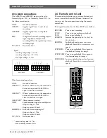
Page 7: ...gnal for multiplexer Output voltage 5 Vdc Output current 100mA DISKFULL Disk full alarm output signal Output voltage 5 Vdc Output current 100mA NC3 NC4 No connections contact voltage max 24 Vdc max switching current 2A dc 2 4 Remote control unit The remote control unit is an accessory that makes it easy to control the Eazeo DVR from a distance You can carry out the main operations using the remote...

Page 8: ...OP key to stop playing back Fast Forward Press PLAY key to start playing back Turn the Shuttle Ring clockwise and fast forward playback starts The speed is shown on the display normal play speed 2x 4x 8x 16x 32x 640x Reverse Playback Press PLAY key to start playing back Turn the Shuttle Ring counterclockwise and fast reverse playback starts The speed is shown on the display normal play speed 2x 4x...

Page 9: ...y Press the Play key to start playing back Press the Pause key to freeze the picture Turn the Jog Dial clockwise or counterclockwise to move to the desired image Press the Copy key to enter the copy mode Turn the Jog Dial to select the desired camera image While the image is displayed press the Copy key again The message Copying appears on the screen during the process The message Success and the ...

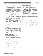
Page 10: ...KB BASIC 25 KB STANDARD 30 KB HIGH 35 KB SUPERIOR 40 KB MULTIPLEXER Select Multiplexer connection or one camera connection ON The video input from MUX MAIN MONITOR connector at the rear panel is looped through to the MONITOR OUT when the recorder is not in MENU mode OFF The main monitor output is same as video out connector all the time VEXT There are two modes for Time lapse recording 1 FIELD 1 2...

Page 11: ...ects the day or set of days for the timer DLY every day WDAY Monday to Friday WEND Saturday and Sunday Individual days of the week START Enter the start time for timer recording STOP Enter the end time for timer recording STOP time needs to be later than the START time e g START 16 00 STOP 03 00 is not correct START 16 00 STOP 00 00 is not correct START 16 00 STOP 23 59 is correct SPEED When SPEEE...

Page 12: ...P Water mark appears at the top 4 8 Network menu IP ADDRESS Fill in the IP address of the unit in the network system NETMASK ADDRESS Fill in the Netmask of the unit in the network system GATEWAY ADDRESS Fill in the Gateway address of the unit in the network system SETUP USER Three user names and passwords can be set up A setup menu is available for each of the three users The Eazeo DVR Login page ...

Page 13: ...lect the video system NTSC or PAL requires power reset to activate DISK RENEW Press Enter to erase or not to erase HDD The confirmation dialog box appears on the screen Select Yes or No and then press ENTER SYSTEM UPDATE Press Enter to update the system or not YES Copy the update file onto the Compact Flash card on the PC and then insert the Compact Flash card into the slot Press ENTER key to upda...

Page 14: ...the Live mode the Playback mode or for logging out Information regarding the status of the system is also shown at the bottom of the screen The present system status and the date and time are shown The icons on the right select the cameras and determine how these are displayed on the screen Playback controls are also located on the right The search function allows you to select a clip for playback...

Page 15: ...remote control mode only allowed with access level SUPER You can now start or stop playback and recording remotely Control for playback speed Control for playback position by search feature 5 2 2 Live mode icons Only the camera icons and the camera view icons are enabled in the view mode 5 2 3 Search icons The system gives you three ways to select video for playing Play video selected by segment l...

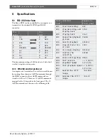
Page 16: ...0 ASCII commands mapped to the 30 keypads in the front panel The 30 ASCII commands are shown on the following table Pin Pin Eazeo HOST 1 NC 1 NC 2 TXD 2 RXD 3 RXD 3 TXD 4 NC 4 DTR 5 GROUND 5 GROUND 6 NC 6 DSR 7 NC 7 RTS 8 NC 8 CTS 9 5V 9 NC ASCII CODE FUNCTION Keypad in front panel K01 Start Recording REC K03 Stop Recording and Playing back STOP K04 Playing back PLAY K05 Pause the playback picture...

Page 17: ...72 1481 1111 889 741 635 556 1 5 120 1975 1481 1185 988 847 741 1 0 168 2963 2222 1778 1481 1270 1111 0 5 240 5926 4444 3556 2963 2540 2222 0 2 480 14815 11111 8889 7407 6349 5556 0 1 960 29630 22222 17778 14815 12698 11111 Average File size 15KB 20KB 25KB 30KB 35KB 40KB NTSC Recording Rate IPS Recording Speed Hours Picture Quality Lower Low Basic Standard High Superior 30 6 99 74 59 49 42 37 20 1...

Page 18: ...Search Date time segment list or event alarm General Video loss detection Yes Power loss detectionYes Alarm log Yes User interface Menu driven Setup By on screen display menu User input device Front panel keypad remote control IR with wired receiver optional Image export Built in Compact Flash slot Security Password protection Power supply 100 240 Vac 50 60 Hz Power consumption 40 W Timer Weekly t...

Page 19: ...Bosch Security Systems 2003 11 Eazeo DVR Installation Manual Chapter 6 EN 21 ...

Reviews: