background image

Electric Drives

and Controls


Hydraulics

Linear Motion and

Assembly Technologies


Pneumatics


Service

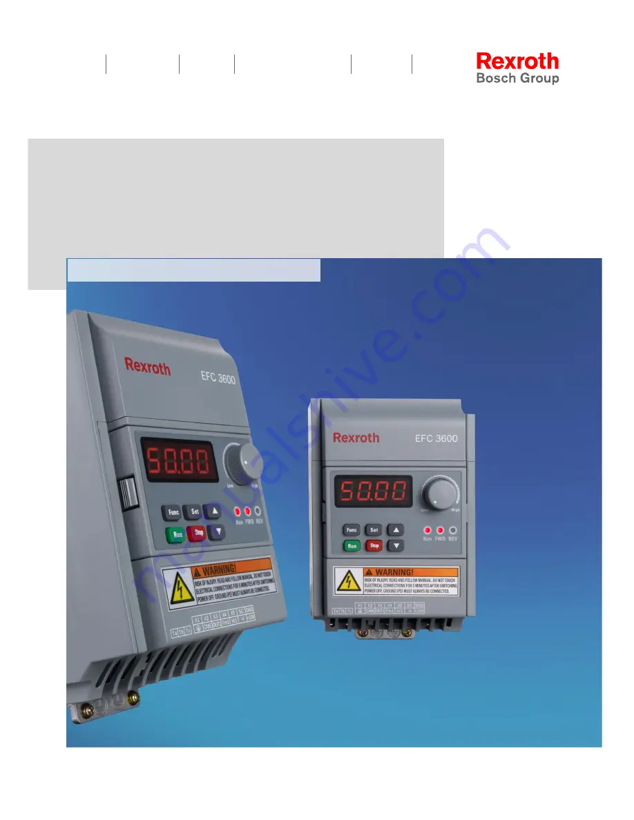
Rexroth Frequency Converter

EFC 3600

R912003768

Edition 01

Operating Instructions

Summary of Contents for Rexroth EFC 3600

Page 1: ...Electric Drives and Controls Hydraulics Linear Motion and Assembly Technologies Pneumatics Service Rexroth Frequency Converter EFC 3600 R912003768 Edition 01 Operating Instructions ...

Page 2: ...r the pay ment of damages All rights are reserved in the event of the grant of a patent or the registration of a utility model or design DIN 34 1 Validity The specified data is for product description purposes only and may not be deemed to be guaranteed unless expressly confirmed in the contract All rights are reserved with respect to the content of this documentation and the availability of the p...

Page 3: ... letto compreso e osservato per intero la documentazione e le indicazioni di sicurezza fornite con il prodotto Se non dovesse essere presente la documentazione nella vostra lingua siete pregati di rivolgervi al rivenditore Bosch Rexroth competente Español Los productos no se pueden poner en servicio hasta después de haber leído por completo comprendido y tenido en cuenta la documentación y las adv...

Page 4: ...era Bosch Rexroth Magyar Üzembe helyezés előtt olvassa el értelmezze és vegye figyelembe a csomagban található dokumentumban foglaltakat és a biztonsági útmutatásokat Amennyiben a csomagban nem talál az Ön nyelvén írt dokumentumokat vegye fel a kapcsolatot az illetékes Bosch Rexroth képviselővel Polski Produkty wolno uruchamiać dopiero po przeczytaniu wszystkich dokumentów dostarczonych wraz z pro...

Page 5: ...ladıktan ve dikkate aldıktan sonrak i leme koyun Şayet size ulusal dilinizde evraklar teslim edilmemiş ise sizinle ilgili olan Bosch Rexroth dağıtım ortağınla irtibata geçin 中文 请在完全通读 理解和遵守随同产品提供的资料和安全提示后才使用这些产品 若产品资料还未翻译成您本国语言 请联系 Bosch Rexroth 相应的销售伙伴 日本語 本製品をお使いになる前に 必ず同封の文書および安全注意事項を全部お読みになり 理解した上で指示に従って本製品を使用していただきますようお願いいたします 同封の文書がお客様の言語で書かれていない場合は どうぞ Bosch Rexroth 製品の販 売契約店までお問い合わせください 한국...

Page 6: ...Bosch Rexroth AG DOK RCON03 EFC 3600 IT01 EN P Rexroth Frequency Converter EFC 3600 IV 235 ...

Page 7: ...ction Against Magnetic and Electromagnetic Fields During Operation and Mounting 16 2 10 Protection Against Contact with Hot Parts 17 2 11 Protection During Handling and Mounting 18 3 Important Directions for Use 19 3 1 Appropriate Use 19 3 2 Inappropriate Use 19 4 Delivery and Storage 20 4 1 Product Identification 20 4 2 The Scope of Supply 21 4 3 Transport of the Components 22 4 4 Storage of the ...

Page 8: ... Display 43 6 3 LED Indicator 44 6 4 Menu Structure 45 6 5 Example of Operating Panel Operation 46 7 Commissioning 47 7 1 Checking and Preparation before Commissioning 47 7 2 Commissioning Process 48 7 3 EFC 3600 Basic Parameter Fast Settings 50 7 4 Restore Parameters to Factory Defaults 51 7 5 Solutions for Simple Faults during Commissioning 52 8 Parameter Settings 53 8 1 Group b0 System Paramete...

Page 9: ...Data 141 10 2 Electrical Parameter 144 10 3 Derating of Electrical Data 145 11 Electromagnetic Compatibility EMC 147 11 1 EMC Requirements 147 11 2 Ensuring the EMC Requirements 154 11 3 EMC Measures for Design and Installation 156 12 Accessories 166 12 1 Brake Resistor 166 12 2 Communication Interface 171 12 3 Accessories for Control Cabinet Mounting 171 13 Communication Protocols 172 13 1 Brief ...

Page 10: ... and Support 193 16 Disposal and Environmental Protection 194 16 1 Disposal 194 16 2 Environmental Protection 194 17 Appendix 195 17 1 Appendix 1 Abbreviations 195 17 2 Appendix 2 Parameter List 195 17 3 Appendix 3 Type Coding 225 Index 231 Bosch Rexroth AG Table of Contents DOK RCON03 EFC 3600 IT01 EN P Rexroth Frequency Converter EFC 3600 VIII 235 ...

Page 11: ...ric Drives and Controls Safety cautions 3 Important Directions for Use 4 Delivery and Storage Product information 5 Mounting and Installation 6 Operating Panel Actual applications for operators and repairers 7 Commissioning 8 Parameter Settings 9 Diagnosis 10 Technical Data 11 Electromagnetic Compatibility EMC 12 Accessories 13 Communication Protocols 14 Maintenance Maintenance information 15 Serv...

Page 12: ... of safety devi ces may result in material damage bodily harm electric shock or even death WARNING Read these instructions before the initial start up of the equipment in order to eliminate the risk of bodily harm or material damage Follow these safety instructions at all times Bosch Rexroth is not liable for damages resulting from failure to observe the warnings provided in this documentation The...

Page 13: ...rained and qualified for the use and operation of the device may work on this device or within its proximity They need to have adequate knowl edge in product assembly mounting and operation They are capable of understand ing all warning messages marked in the instructions and respective prevention measures Furthermore they must be trained instructed and qualified to switch electrical cir cuits and...

Page 14: ... symbols and degree of hazard 2 5 Hazards by Improper Use High electric voltage and high working current Risk of death or severe bodily injury by electric shock DANGER Dangerous movements Danger to life severe bodi ly harm or material damage by unintentional motor movements DANGER High electric voltage because of incorrect connec tion Risk of death or bodily injury by electric shock WARNING Health...

Page 15: ... maintain and repair this equipment Follow general construction and safety regulations when working on electrical power installations Before switching on the device the equipment grounding conductor must have been non detachably connected to all electrical equipment in accordance with the connec tion diagram Do not operate electrical equipment at any time even for brief measurements or tests if th...

Page 16: ... inter national standards With electrical drive and filter components observe the following High housing voltage and large leakage current Risk of death or bodily injury by electric shock DANGER Before switching on the housings of all electrical equipment and motors must be connected or grounded with the equipment grounding conductor to the grounding points This is also applicable before short tes...

Page 17: ...vements can occur immediately after equipment is switched on or even after an unspecified time of trouble free operation The monitoring in the drive components will normally be sufficient to avoid faulty opera tion in the connected drives Regarding personal safety especially the danger of bodily harm and material damage this alone cannot be relied upon to ensure complete safety Until the integrate...

Page 18: ...e danger zone The standard equipment motor brake or an external brake controlled directly by the drive controller are not sufficient to guarantee personal safety Disconnect electrical power to the equipment using a master switch and secure the switch against reconnection for Maintenance and repair work Cleaning of equipment Long periods of discontinued equipment use Prevent the operation of high f...

Page 19: ...rns CAUTION Do not touch surfaces of device housings and chokes in the proximity of heat sour ces Danger of burns Do not touch housing surfaces of motors Danger of burns According to operating conditions temperatures can be higher than 60 C 140 F during or after operation Before accessing motors after having switched them off let them cool down for a sufficiently long time Cooling down can require...

Page 20: ...ssembly Use suitable devices for assembly and transport Avoid jamming and bruising by appropriate measures Always use suitable tools Use specific tools in different circumstances Use lifting equipment and tools in the correct manner If necessary use suitable protective devices for example safety goggles safety shoes safety gloves Do not stand under hanging loads Immediately clean up any spilled li...

Page 21: ...remain in their original state in other words no structural changes are permitted It is not permitted to decompile software products or alter source codes Do not mount damaged or faulty products or use them in operation Make sure that the products have been installed in the manner described in the rele vant documentation 3 2 Inappropriate Use Using the frequency converters outside of the operating...

Page 22: ...e as you ordered immediately after receipt unpacking If the model is wrong please contact Bosch Rexroth distributor for replacement Fig 4 1 Packing nameplate For the meaning of the typecode please refer to chapter 17 3 Appendix 3 Type Coding on page 225 Bosch Rexroth AG Delivery and Storage DOK RCON03 EFC 3600 IT01 EN P Rexroth Frequency Converter EFC 3600 20 235 ...

Page 23: ...ation or loose parts immediately af ter unpacking In case of damage contact the forwarder at once and arrange for a thor ough review of the situation This is also applicable if the packaging is undamaged 4 2 The Scope of Supply Standard model Frequency Converter EFC 3600 protection class of IP20 Control cabinet mounting Integrated brake chopper Operating panel Safety notes Optional accessories Ope...

Page 24: ...ctrolytic capacitors which may deteriorate during storage When storing these components for a long period of time remember to operate them once a year Run frequency converter EFC 3600 under power ULN for at least 1 hour For more information of electrolytic capacitors please contact service Ambient and operating conditions Storage Description Symbol Unit Value Temperature range Ta_store 25 55 Relat...

Page 25: ...ng and Installation 5 1 EFC 3600 Dimensions Figure Fig 5 1 EFC 3600 figure of model A B and C DOK RCON03 EFC 3600 IT01 EN P Rexroth Frequency Converter EFC 3600 Bosch Rexroth AG Mounting and Installation 23 235 ...

Page 26: ...Fig 5 2 EFC 3600 figure of model D Bosch Rexroth AG Mounting and Installation DOK RCON03 EFC 3600 IT01 EN P Rexroth Frequency Converter EFC 3600 24 235 ...

Page 27: ... 3P4 MDA 1 52 D 2K20 1P2 MDA 120 110 210 200 221 4 5 138 130 5 M4 2 35 2K20 3P4 MDA 2 25 4K00 3P4 MDA 2 36 Fig 5 1 EFC 3600 dimensions The complete type code for frequency converter is EFC3600 xKxx xPx MDA 7P NNNN for details please see chapter 17 3 Appendix 3 Type Coding on page 225 2 screws are needed for mounting of EFC 3600 model A B or C 4 screws are needed for mounting of EFC 3600 model D DO...

Page 28: ...entilation hole which enables parallel mounting of EFC 3600 with zero distance If one frequency converter is arranged above another make sure that the upper limit of air temperature into the inlet is not exceeded See fig 10 1 General technical data on page 141 A baffle plate is recommended between the frequency converters to prevent the rising hot air being drawn into the upper frequency convert e...

Page 29: ...tions The natural convection supports the forced cooling air current This avoids the generation of pockets of heat in the component G2 180 to normal mounting position G3 Turned by 90 from vertical to horizontal mounting position G4 Bottom mounting mounting sur face on bottom of control cabinet G5 Top mounting mounting surface at top of control cabinet Fig 5 4 Frequency converter mounting position ...

Page 30: ...1 phase 200 VAC Class Fig 5 5 Block diagram 1AC It is recommended to use shielded cable to connect the motor Bosch Rexroth AG Mounting and Installation DOK RCON03 EFC 3600 IT01 EN P Rexroth Frequency Converter EFC 3600 28 235 ...

Page 31: ...00 VAC Class Fig 5 6 Block diagram 3AC It is recommended to use shielded cable to connect the motor DOK RCON03 EFC 3600 IT01 EN P Rexroth Frequency Converter EFC 3600 Bosch Rexroth AG Mounting and Installation 29 235 ...

Page 32: ...als and the AC input power supply It is preferable to connect a magnetic contactor MC in series to en sure both the action of frequency converter protection and shutting off of power sup ply Surge absorbers should be added at both sides of the magnetic contactor If the wire between the frequency converter and the motor is very long particularly with low output frequency the voltage drop may lead t...

Page 33: ... 2 It is recommended to use 4 core cables to connect the motor Cables are connec ted to motor terminals PE U V W 3 If shielded cables are used the shield layer of the motor cable should be securely connected to on the bottom right of the heat sink The shielded cables for the control signals should be connected to on control terminal block It is recommended to use shielded cables in accordance with...

Page 34: ... to fig 5 12 Fuse and cable dimensions on page 35 It will shorten the life time of relay contacts and DC bus capacitors and may destroy the resistor for capacitor charging and current limitation Bosch Rexroth AG Mounting and Installation DOK RCON03 EFC 3600 IT01 EN P Rexroth Frequency Converter EFC 3600 32 235 ...

Page 35: ...nding and input PE 3 phase 400 VAC class L1 L2 L3 Mains power supply inputs U V W Frequency converter outputs to be connected to the motor B Reserved terminal for external brake resistor DC positive bus output Grounding and input PE Fig 5 2 Main circuit terminals description Do not use terminal L3 for 1P 200 VAC class models Input PE terminals located at bottom left of the heat sink Grounding term...

Page 36: ...are relevant for the re spective application and the place of installation Also factors such as in stallation methods grounding insulation and over voltage protection must be taken into consideration National standards such as NFPA in the USA regional provisions ground operating temperature operating cycles over voltage protection and system configuration can have a decisive impact on the dimensio...

Page 37: ...WG Cable size mm 2 AWG Cable size mm 2 AWG Torque Nm lb in screw size 1 phase 200 VAC class 0 4 10 2 0 14 2 0 14 0 8 7 M3 6 8 0 8 7 M3 0 75 16 2 0 14 2 0 14 0 8 7 M3 6 8 0 8 7 M3 1 5 20 2 0 14 2 0 14 0 8 7 M3 6 8 0 8 7 M3 2 2 25 3 5 12 3 5 12 1 2 10 M4 6 8 1 2 10 M4 3 phase 400 VAC class 0 4 6 2 0 14 2 0 14 0 8 7 M3 6 8 0 8 7 M3 0 75 10 2 0 14 2 0 14 0 8 7 M3 6 8 0 8 7 M3 1 5 10 2 0 14 2 0 14 0 8 ...

Page 38: ...les and lines and gG general purpose fuse link for general installations protect the lines in the frequency converter system To protect the semiconductors in the input of supply units and frequen cy converters you can use fuses of characteristic gR USA Canada Class J 600 V 5 10 Main Circuit Wiring Steps Fig 5 10 Main circuit wiring steps Bosch Rexroth AG Mounting and Installation DOK RCON03 EFC 36...

Page 39: ...ulation for wiring of the control circuit according to the di mensions given below Too long stripping may cause short circuit of adjacent wires too short stripping may lead to wires becoming loose Fig 5 11 Wire stripping length Disconnection of cables or damage of screws may cause incorrect operation if screws are not fixed correctly 5 12 Control Circuit Terminals Fig 5 12 Control circuit terminal...

Page 40: ...A Input resistance 499 Ω Resolution 1 800 GND Shared connection for analog signals Isolated from SC Earth Shielding terminal Digital outputs OUT1 CME Open collector output 1 Programmable digi tal output with multi ple functions see parameter E1 00 Open collector outputs DC 30 V 50 mA Ta Relay changeover contacts Programmable relay output see parame ter E1 02 Rated capacity of contact transmitter 2...

Page 41: ...igital Inputs The factory default setting is NPN For disassembly and mounting of the operating panel see chapter 14 4 Operating Panel Removal and Mounting on page 189 DOK RCON03 EFC 3600 IT01 EN P Rexroth Frequency Converter EFC 3600 Bosch Rexroth AG Mounting and Installation 39 235 ...

Page 42: ...5 15 NPN and PNP Modes Fig 5 14 NPN and PNP modes Bosch Rexroth AG Mounting and Installation DOK RCON03 EFC 3600 IT01 EN P Rexroth Frequency Converter EFC 3600 40 235 ...

Page 43: ...n 20 m Shielded cables must be used Incorrect operation may occur due to interference on the analog signal In such cases connect a capacitor and ferrite core at the output side of the analog signal as shown above 5 17 Recommendations on Control Circuit Wiring 0 2 1 5 mm2 cables are recommended for wiring of the control circuit DOK RCON03 EFC 3600 IT01 EN P Rexroth Frequency Converter EFC 3600 Bosc...

Page 44: ...5 18 Control Circuit Wiring Steps Fig 5 16 Control Circuit Wiring Steps Bosch Rexroth AG Mounting and Installation DOK RCON03 EFC 3600 IT01 EN P Rexroth Frequency Converter EFC 3600 42 235 ...

Page 45: ...keys allow the user to program the frequency converter Fig 6 1 Operating panel 6 2 Seven segment Display Fig 6 2 Seven segment display Display has only 4 digits but values with up to 5 digits may be displayed To view the first 4 digits press buttons Func To view the last 4 digits press buttons Func DOK RCON03 EFC 3600 IT01 EN P Rexroth Frequency Converter EFC 3600 Bosch Rexroth AG Operating Panel ...

Page 46: ...icator Run also blinks during dead zone time of forward and reverse rotation period of automatic error reset and waiting time for re starting after power fault Bosch Rexroth AG Operating Panel DOK RCON03 EFC 3600 IT01 EN P Rexroth Frequency Converter EFC 3600 44 235 ...

Page 47: ...d to toggle between menu op tions and set parameters with buttons Func Set and The monitoring display mode will be activated if there is no operation for more than 60 seconds DOK RCON03 EFC 3600 IT01 EN P Rexroth Frequency Converter EFC 3600 Bosch Rexroth AG Operating Panel 45 235 ...

Page 48: ...6 5 Example of Operating Panel Operation Fig 6 5 Example of operating panel operation Bosch Rexroth AG Operating Panel DOK RCON03 EFC 3600 IT01 EN P Rexroth Frequency Converter EFC 3600 46 235 ...

Page 49: ... the power supply and that the ground terminal is well connected Ensure that there are no short circuits between terminals live terminals or short cir cuit to ground Ensure that terminal connections connectors and screws are secure Ensure that the motor is not connected to any load Check that all switches are off before powering on to ensure that the frequency con verter will not be started and no...

Page 50: ... runs smoothly Whether there is any abnormal noise or problem Observe the running and immediately stop the motor by shutting off the pow er if any abnormality occurs Restart commissioning only after the fault causes have been removed 5 Rotate the potentiometer clockwise rightwards The motor accelerates 6 Rotate the potentiometer counterclock wise leftwards The motor decelerates 7 Press Stop key Wh...

Page 51: ...requency is set by the potentiometer on the operating panel After powering on please confirm The set frequency is displayed no error display The monitoring parameter is consistent with the actual situation The frequency converter initially displays output frequency after being energized You may change it to another parameter as instructed in b0 30 and b0 31 The factory defaults are based on standa...

Page 52: ...quency 50 00 400 00 Hz 0 01 Hz 50 00 Hz Stop b1 06 Upper frequency b1 07 b1 05 0 01 Hz 50 00 Hz Run Stop b1 07 Lowest frequency 0 00 b1 06 0 01 Hz 0 00 Hz Run Stop b1 04 Digital set frequency b1 07 b1 06 0 01 Hz 50 00 Hz Run Stop b1 10 Direction control 0 3 1 0 Stop b1 20 Acceleration time 1 0 1 6000 0s 0 1s 5 0s Run Stop b1 21 Deceleration time 1 0 1 6000 0s 0 1s 5 0s Run Stop b1 22 Acceleration ...

Page 53: ... the parameter settings match with the motor and the field applica tions after factory defaults restore Adjust the parameter settings after factory defaults restore if necessary Operating frequency Set by the potentiometer b1 00 Acc Dec time Linear Acc for 5s Dec for 5s b1 20 b1 21 Protection mode in case of motor overload and overheat Motor rated current S2 04 thermal motor time constant S2 23 lo...

Page 54: ...essing the Run key Incorrect wiring Check if U V W outputs of the main circuit are shorted or grounded The motor runs in the direction opposite to expected Change the sequence of any two phases of U V and W The motor vibrates and runs in uncertain directions after each starting One phase of U V and W is disconnected output phase loss Fig 7 4 Solutions for simple faults during commissioning Bosch R...

Page 55: ...facture if you forget the set password User password protection will not affect frequency modification with keys in RUN mode It means that the frequency may still be saved ac cording to the selected saving mode when the frequency setting source is via digital setting See descriptions in parameter b1 01 b0 01 Manufacturer password Setting range 0 65535 Minimum unit 1 Factory default 0 Manufacturer ...

Page 56: ...ce b1 02 First RUN command source b1 04 Digital set frequency b1 05 Max frequency b1 06 Upper frequency b1 07 Lowest frequency b1 10 Direction control b1 20 Acceleration time 1 b1 21 Deceleration time 1 b1 22 Acceleration deceleration curve mode b1 30 Starting mode b1 40 Stopping mode S0 00 V F curve mode S2 00 Rated motor frequency S2 01 Rated motor rotation speed S2 02 Rated motor power S2 03 Ra...

Page 57: ...er b0 05 will be set to zero automatically b0 06 Parameter replication Setting range 0 2 Minimum unit 1 Factory default 0 0 No action 1 Read parameter All except read only parameters are copied from the frequency converter to the ope rating panel 2 Write parameter All except read only parameters are copied from the operating panel to the frequen cy converter Read only parameters all monitoring par...

Page 58: ...oss and temperature will be increased A lower PWM frequency will reduce the power loss and temperature of frequency converter For the temperature voltage and current derating figures related to PWM frequency please refer to chapter 10 3 Derating of Electrical Data on page 145 To obtain the best performance of the output frequency the carrier fre quency needs to be set as below Set b0 21 10 Max fre...

Page 59: ...lue 16 Module temperature 17 Firmware version 1 18 Firmware version 2 19 Firmware version 3 20 Actual carrier frequency b0 32 User defined proportion factor for velocity Setting range 0 01 100 0 Minimum unit 0 01 Factory default 1 00 b0 33 PID reference feedback coefficient Setting range 0 01 100 0 Minimum unit 0 01 Factory default 1 00 Used for monitoring function They only affect the displayed v...

Page 60: ...ring value d0 15 PID feedback x b0 33 With d0 15 PID feedback engineering value b0 33 PID reference feedback coefficient Users may convert the PID engineering value to any other form they feel easy to under stand via parameter b0 33 In case the value of a monitoring parameter is too big to fit into the 4 digit display If the display value is between 1000 0 and 9999 9 1000 9999 is dis played withou...

Page 61: ...arameters E0 10 E0 28 3 Given by external analog AIC Set the frequency by external analog current input The input resistance is 499 Ω Please also set parameters E0 10 E0 28 4 Set by external UP DOWN terminals In this mode the output frequency can be adjusted easily with the UP DOWN and RESET terminals For details please see parameters S3 32 and S3 33 5 Given via communication Set output frequency ...

Page 62: ...ered off or stopped Value changes set by b1 04 are always retained b1 02 The first RUN command source Setting range 0 2 Minimum unit 1 Factory default 0 0 Inputting commands via panel Using keys Run and Stop on the panel to run and stop the frequency converter 1 Inputting commands via external terminals Using external terminals to control run stop forward and reverse For details please refer to th...

Page 63: ...t frequency set according to the requirements in applications b1 08 Lower frequency mode Setting range 0 1 Minimum unit 1 Factory default 0 b1 09 Hysteresis frequency width Setting range 0 00 b1 07 Minimum unit 0 01 Factory default 0 00 Two running modes are available when the lowest frequency is reached b1 08 0 Running with 0 Hz When the lower frequency is reached the frequency converter is runni...

Page 64: ...nd external terminal 0 Both directions 1 Forward only When reverse rotation command is active the frequency converter will stop immediately and the error shows up 2 Reverse only When forward rotation command is active the frequency converter will stop immediately and the error shows up 3 Inverse default direction An adjustable dead zone time between forward and reverse can be set please refer to S...

Page 65: ... Forward STOP with error Reverse Reverse 3 Inverse default direction Forward Reverse Reverse Forward For STOP with error please see chapter 9 5 Diagnosis on Errors on page 128 Normally each RUN STOP command source has its own direction command source The generated direction is further controlled by internal direction control b1 10 Frequency source RUN STOP command source Direction command source M...

Page 66: ...tting source b1 00 and the second frequency setting source b1 16 It is allowed to use any of the fre quency command sources or the combination of them When the combination of two sources is active The reference and calculation of each part of the combination follows the rules and definitions when it is used as a single command source input Each part of the com bination has the full frequency range...

Page 67: ... is disabled and switching terminal is active frequency command value is given by the second frequency setting source b1 16 Second frequency setting source Setting range 0 6 Minimum unit 1 Factory default 2 0 Given by panel potentiometer 1 Given by panel digital setting 2 Given by external analog AIV 3 Given by external analog AIC 4 Set by external UP DOWN terminals 5 Given via communication 6 Giv...

Page 68: ...ry default 5 0s Fig 8 5 Acc Dec time For EFC 3600 acceleration deceleration time is defined as the time from zero to the Max frequency and from the Max frequency to zero 4 groups of acceleration decel eration time are available which can be selected via external terminals For related set tings please see E0 01 E0 05 and E2 00 E2 05 Jog function has its own acceleration and deceleration time b1 22 ...

Page 69: ...erter to linear curve or S curve in start stop forward reverse acceleration deceleration processes b1 22 0 Linear mode The output frequency is increased or decreased in linear as shown in figure below Fig 8 6 Linear mode b1 22 1 S curve The output frequency is increased or decreased in an S curve the S curve mode is used to achieve smooth start or stop as shown in figure below DOK RCON03 EFC 3600 ...

Page 70: ...ing mode Setting range 0 2 Minimum unit 1 Factory default 0 b1 31 Starting frequency Setting range 0 00 50 00 Hz Minimum unit 0 01 Hz Factory default 0 05 Hz b1 32 Starting frequency holding time Setting range 0 0 20 0s Minimum unit 0 1s Factory default 0 1s b1 33 Starting DC braking time Setting range 0 0 20 0s 0 0 represents no action of starting DC braking Minimum unit 0 1s Bosch Rexroth AG Par...

Page 71: ...current frequency of the motor to realize smooth starting without shock to the rotating motor This mode is suitable for restarting after transi ent power fault in the case of a large inertia load When the frequency converter is starting and accelerating if the set fre quency is lower than the Starting frequency b1 31 the frequency con verter firstly starts at the starting frequency and runs for St...

Page 72: ...ally freewheels to stop 2 Freewheeling in STOP command decelerating when direction changes This function also allows the frequency converter freewheeling to stop if STOP com mand is active and decelerating to stop according to stopping mode deceleration time and stopping DC braking if necessary when direction change command is ac tive during running The digital input freewheeling to stop is an add...

Page 73: ...nly be activated when a stop command is active and b1 40 0 and output frequency b1 41 and digital input Stopping DC braking enabled is active or b1 42 0 When b1 42 0 and digital input Stopping DC braking enabled Xn ter minal is set as 13 is active the frequency converter will keep on DC brak ing before the digital input goes inactive even if the time b1 42 is elapsed DOK RCON03 EFC 3600 IT01 EN P ...

Page 74: ... a gain to the V F pattern needed for fine tune of this function which determines the level of overexcitation Higher value of gain will increase the braking capability of overexcitation Reduce the value of b1 45 when the motor slip gets too high which can trigger overcurrent OC frequency converter overload OL 1 or motor overload OL 2 faults b1 46 b1 49 Reserved Bosch Rexroth AG Parameter Settings ...

Page 75: ...uency control which is suitable for normal constant torque loads as shown in the figure below Fig 8 9 Linear curve 1 Square curve This mode refers to square voltage frequency control which is suitable for variable torque loads of fans pumps etc DOK RCON03 EFC 3600 IT01 EN P Rexroth Frequency Converter EFC 3600 Bosch Rexroth AG Parameter Settings 73 235 ...

Page 76: ...trifuges etc Fig 8 11 User defined multipoint curve Excessive low frequency voltages may cause the motor to overheat and be destroyed and the fre quency converter may stall due to overcurrent or ac tivate overcurrent protection WARNING Bosch Rexroth AG Parameter Settings DOK RCON03 EFC 3600 IT01 EN P Rexroth Frequency Converter EFC 3600 74 235 ...

Page 77: ...uency 3 Setting range 0 0 120 0 Rated motor voltage Minimum unit 0 1 Factory default 0 0 Each V F frequency is limited by neighbouring V F frequencies In this case the fre quencies of these points must be set in an ascending sequence 0 V F frequency 1 V F frequency 2 V F frequency 3 Motor rated frequency It is necessary to have voltages above rated voltage in the field weakening range For this the...

Page 78: ...y In this case the output voltage is limited to 100 even if S0 06 V F voltage 3 is above 100 S0 07 S0 19 Reserved S0 20 Rated motor slip frequency Setting range 0 00 20 00 Hz Minimum unit 0 01 Hz Factory default 0 00 Hz Bosch Rexroth AG Parameter Settings DOK RCON03 EFC 3600 IT01 EN P Rexroth Frequency Converter EFC 3600 76 235 ...

Page 79: ...ata with the formular below ns synchronous speed P numbers of pole pairs S rated slip nn rated speed fs rated slip frequency fn rated frequency Fig 8 15 Slip frequency calculation If the slip frequency compensation is too large the motor speed may exceed the synchronous speed Slip compensation will not work under circumstances of acceleration deceleration regenerative mode and DC braking S0 21 Vol...

Page 80: ...t value is linear square decreasing with increasing output frequency before a certain frequency For linear V F curve this function is only valid before half of base frequency for ex ample if Base frequency S2 00 is 50 00 Hz then torque boost function is only valid before 25 00 Hz Fig 8 16 Linear V F curve manual torque increase For square V F curve this function is valid before base frequency for ...

Page 81: ...atically the percentage of output voltage increase based on the output frequency and the load current The linear and square V F curves for auto matic torque boost are shown as below See parameter S0 22 for more details Fig 8 18 Linear V F curve auto torque boost DOK RCON03 EFC 3600 IT01 EN P Rexroth Frequency Converter EFC 3600 Bosch Rexroth AG Parameter Settings 79 235 ...

Page 82: ...ltage boost R1 stator resistance I1 stator current Thus R1 should be preset or calculated or tuned and then input to S2 10 S0 24 Heavy load voltage stabilization Setting range 0 disable 1 enable Minimum unit 1 Factory default 1 Used to depress the fluctuations in output voltage and current which are caused by bigger impact to DC bus voltage in case of heavy load Bosch Rexroth AG Parameter Settings...

Page 83: ...d The function is useful for loads with large inertia or sudden changes 3 modes of current limitation control can be selected S0 30 0 OFF Current limitation control will not be disabled in any case S0 30 1 OFF at constant speed Current limitation control works during Acc and Dec but does not work at constant speed S0 30 3 ON at constant speed Current limitation control works in all cases Acc Dec a...

Page 84: ...z Minimum unit 0 01 Hz Factory default 50 00 Hz S2 01 Rated motor rotation speed Setting range 1 30000 rpm Minimum unit 1 rpm Factory default Depends on model S2 02 Rated motor power Setting range 0 1 1000 0 kW Minimum unit 0 1 kW Factory default Depends on model S2 03 Rated motor voltage Setting range 0 480 V Minimum unit 1 V Factory default Depends on model S2 04 Rated motor current Setting rang...

Page 85: ...imum unit 1 Factory default 0 The motor parameters S2 00 S2 05 must be set before using Physical data cal culation S2 15 The necessary information can be found on the nameplate of motor S2 15 0 No action S2 15 1 Calculation After the calculation is finished parameters S2 10 S2 14 will be updated S2 15 2 Automatic adjustment while the motor is in static mode S2 15 3 Automatic adjustment while the m...

Page 86: ...al connector of the frequency converter Fig 8 21 Protection with temperature sensor For a good resolution of temperature with continuous sensors in gener al NTCs the value of resistor R in the figure should be close to the sensor resistance at the motor temperature limit For switching sensors in general PTCs the value of resistor R in the figure should be close to the sensor resistance at high tem...

Page 87: ... Setting range 0 00 b1 05 Minimum unit 0 01 Hz Factory default 5 00 Hz S3 01 Jogging acceleration time Setting range 0 1 6000 0s Minimum unit 0 1s Factory default 5 0s S3 02 Jogging deceleration time Setting range 0 1 6000 0s Minimum unit 0 1s Factory default 5 0s Jogging command input has the highest priority and is independent of the RUN STOP command input As long as jogging command is activated...

Page 88: ... to b1 40 Stopping mode S3 05 Skip frequency 1 Setting range 0 00 Hz b1 06 Minimum unit 0 01 Hz Factory default 0 00 Hz S3 06 Skip frequency 2 Setting range 0 00 Hz b1 06 Minimum unit 0 01 Hz Factory default 0 00 Hz S3 07 Skip frequency 3 Setting range 0 00 Hz b1 06 Minimum unit 0 01 Hz Factory default 0 00 Hz S3 08 Skip frequency range Setting range 0 00 30 00 Hz Minimum unit 0 01 Hz Factory defa...

Page 89: ... limit of skip frequency range If the skip frequency range is set to 0 00 Hz no skip frequency control is enabled Do not make the 3 frequency ranges overlap or nest in each other S3 09 Skip window acceleration factor Setting range 1 100 Minimum unit 1 Factory default 1 This parameter makes the acceleration inside the skip window faster the range for this factor is 1 normal acceleration to 100 acce...

Page 90: ...e running command If the frequency converter was running before power off due to 3 wire control then after power on the restart of frequency converter will be decided by the statue of this 3 wire terminal sine it is responsible for STOP If the frequency converter was running before power off due to a power supply interference UE 1 will occur by undervoltage situation the fre quency converter will ...

Page 91: ...set velocity Setting range 0 10 100 0 Hz s Minimum unit 0 01 Hz s Factory default 1 00 Hz s S3 33 UP DOWN terminals initial frequency Setting range 0 b1 06 Minimum unit 0 01 Hz Factory default 0 00 Hz Used to change the output frequency When b1 00 or b1 16 is set to 4 the UP DOWN control is activated as the command value In this mode the output frequency can be adjusted easily with UP DOWN and zer...

Page 92: ...Either Input DOWN Open Closed Open Closed Either Current set frequency of the fre quency converter Hold Decrease Increase Hold Zero UP DOWN Zeroing terminals only work in RUN state Whether the frequencies modified via UP DOWN terminals will or not be saved after power off depends on parameter b1 01 S3 34 Fan control Setting range 0 1 Minimum unit 1 Factory default 0 0 Automatically controlled Auto...

Page 93: ...e one terminal is assigned as FWD E0 01 23 and connected to K1 an other terminal is assigned as REV E0 02 24 and connected to K2 E0 00 0 Forward Stop Reverse Stop Fig 8 27 2 wire control_1 K1 K2 Running status Inactive Inactive Stop Inactive Active Reverse Active Inactive Forward Active Active Stop If both terminals are active at the same time the frequency converter stops according to the stoppin...

Page 94: ...rol An additional terminal needs to be configured as 3 wire running control and con nected as below Fig 8 29 3 wire control K1 is RUN command source K2 is used for direction selection 0 forward 1 reverse K3 is STOP command source 3 wire mode N C terminal FWD input is edge sensitive Bosch Rexroth AG Parameter Settings DOK RCON03 EFC 3600 IT01 EN P Rexroth Frequency Converter EFC 3600 92 235 ...

Page 95: ...28 Minimum unit 1 Factory default 0 E0 02 Terminal X2 Setting range 0 28 Minimum unit 1 Factory default 0 E0 03 Terminal X3 Setting range 0 28 Minimum unit 1 Factory default 0 E0 04 Terminal X4 Setting range 0 28 Minimum unit 1 Factory default 0 E0 05 Terminal X5 Setting range 0 28 Minimum unit 1 Factory default 0 5 external digital input terminals are available with PNP and NPN input modes 0 No a...

Page 96: ...2 41 ON OFF OFF Multi speed frequency 4 E2 13 E2 43 ON OFF ON Multi speed frequency 5 E2 14 E2 45 ON ON OFF Multi speed frequency 6 E2 15 E2 47 ON ON ON Multi speed frequency 7 E2 16 E2 49 Fig 8 2 Multi speed terminal settings 4 Reserved 5 Acceleration deceleration time terminal 1 6 Acceleration deceleration time terminal 2 4 options of acceleration deceleration time are available with the combina...

Page 97: ...the stopping mode configured by b1 40 9 Frequency increment UP command 10 Frequency decrement DOWN command 11 Zeroing of external terminal frequency setting The above three functions are used to change the frequency set with terminals UP DOWN or clear the frequency to 0 Hz by the zeroing terminal See parameters S3 32 and S3 33 12 Reserved 13 Stopping DC braking enabled This function is used when s...

Page 98: ...led This function is used to switch frequency command source between the first channel b1 00 and the second channel b1 16 which is level sensitive When this func tion is inactive the first channel b1 00 is active when this function is active the second channel b1 16 is active If status of external terminals for frequency source switching is changed during run ning the new frequency command is acce...

Page 99: ...s active 23 Forward FWD 24 Reverse REV These two functions are used for RUN STOP command control see parameter E0 00 25 Forward jogging 26 Reverse jogging For jogging functions see parameters S3 00 S3 02 27 Counting input 28 Counting clear The above two functions are counting functions of an external signal See parame ters E1 13 and E1 14 E0 10 Analog input voltage AIV channel gain k1 Setting rang...

Page 100: ...ding to curve 1 min reference Setting range 0 00 b1 06 Minimum unit 0 01 Hz Factory default 0 00 Hz E0 23 Curve 1 max reference Setting range E0 21 100 0 Minimum unit 0 1 Factory default 100 0 E0 24 Frequency corresponding to curve 1 max reference Setting range 0 00 b1 06 Minimum unit 0 01 Hz Factory default 50 00 Hz E0 25 Curve 2 min reference Setting range 0 0 E0 27 Minimum unit 0 1 Factory defa...

Page 101: ...e channel and the set fre quency is illustrated as below Fig 8 31 Relationship between reference channel and set frequency The relationship between the reference frequency after gain and filter processing with the set frequency commands is determined by E0 21 E0 28 and E0 20 AIC and AIV can use both curve 1 and curve 2 E0 21 E0 24 are used to define characteristics of curve 1 See figure below Fig ...

Page 102: ... converter is running The terminal outputs indicating signal when the frequency converter is running and has frequency output including 0 00 Hz 2 DC braking indication When the frequency converter is in the starting or stopping DC braking output is ac tive 3 Frequency converter running at zero speed When the frequency converter is running with zero speed output is active During dead zone time of r...

Page 103: ...l be no pulse output For details of simple PLC control see parameters E2 10 E2 16 and E2 30 E2 50 Fig 8 34 Simple PLC phase completion indication If the running time of one of the stages is so short that it is finished before the phase completion signal of the previous stage is deactivated the sig nal remains active and the pulse duration calculation is restarted 8 Simple PLC cycle completion indi...

Page 104: ...ernal digital input group 14 Fault output Active when error occurs inactive when error is reset 15 Reserved 16 Target counter value reached When number of input pulse equals to the setting value defined in E1 14 the output is active until next pulse arrives 17 Middle counter value reached When number of input pulse equals to the setting value defined in E1 13 the output is active until the next pu...

Page 105: ...50 00 Hz E1 06 Frequency detection level FDT1 width Setting range 0 00 E1 05 Minimum unit 0 01 Hz Factory default 1 00 Hz E1 07 Frequency detection level FDT2 Setting range 0 00 400 0 Hz Minimum unit 0 01 Hz Factory default 25 00 Hz E1 08 Frequency detection level FDT2 width Setting range 0 00 E1 07 Minimum unit 0 01 Hz Factory default 1 00 Hz When the output frequency exceeds the frequency set by...

Page 106: ...1 Factory default 100 0 When the output current exceeds the threshold defined in E1 09 for delay time defined in E1 11 the function is active The signal is immediately deactivated when the output current is lower than the threshold defined in E1 09 E1 11 Frequency converter overload pre warning delay Setting range 0 0 20 0s Minimum unit 0 1s Factory default 2 0s E1 12 Motor overload pre warning de...

Page 107: ...x 16 Target counter value reached and DOutx 17 Middle counter value reached remain active These signals are reset by the next valid triggering edge of the input terminal signal parameterized as counting signal input after the counter value is cleared If one of the parameters E1 13 E1 14 and or digital input terminal configuration E0 01 E0 05 is changed the counter value is reset and digital output...

Page 108: ...10 V refers to 0 1 2 x rated power E1 30 6 AIV 0 10 V 2 10 V refers to 0 10 V E1 30 7 AIC 0 10 V 2 10 V refers to 4 20 mA Frequency converter rated voltage is defined in parameter b0 20 E1 31 is used to select output signals 0 10 V or 2 10 V E1 32 means the gain applied to analog output voltage For example When the gain value is 0 00 then the analog output voltage will be 0 V In the case of FM1 ch...

Page 109: ...quency 1 E2 12 Multi speed frequency 3 See parameter E2 10 Multi speed frequency 1 E2 13 Multi speed frequency 4 See parameter E2 10 Multi speed frequency 1 E2 14 Multi speed frequency 5 See parameter E2 10 Multi speed frequency 1 E2 15 Multi speed frequency 6 See parameter E2 10 Multi speed frequency 1 E2 16 Multi speed frequency 7 See parameter E2 10 Multi speed frequency 1 Parameters E2 10 E2 1...

Page 110: ...LC on page 111 4 If the set frequency of next stage is lower than current stage it will decelerate to the next stage with the deceleration time of current stage If the set frequency of next stage is higher than current stage it will accelerate to the next stage with the acceleration time of next stage Simple PLC control Simple PLC is an automatic running mode according to the preset acceleration d...

Page 111: ...ng time of each stage Stage x running time E2 31 Stage x running time has a possible maximum value of 6000 0s the PLC time multipli er E2 31 has a maximum value of 60 and there are 8 possible stages 0 7 so the maximum duration of one PLC cycle calculates to 8 6000 0s 60 800 hours E2 35 Stage 0 action selection Setting range 011 012 013 014 021 022 023 024 031 032 033 034 041 042 043 044 111 112 11...

Page 112: ...n E2 50 Stage 7 running time Stage 0 running time Definition of stage x action selection is shown as below Display 2 left most 0 forward running 1 reverse running Display 1 1 Acceleration time 1 set with function code b1 20 2 Acceleration time 2 set with function code E2 00 3 Acceleration time 3 set with function code E2 02 4 Acceleration time 4 set with function code E2 04 Display 0 right most 1 ...

Page 113: ...codes E2 35 E2 37 E2 39 E2 41 E2 43 E2 45 E2 47 E2 49 Via external termi nals External terminals that is 2 wire 3 wire control mode Via communication Set by communication Simple PLC Via operating panel Function codes E2 35 E2 37 E2 39 E2 41 E2 43 E2 45 E2 47 E2 49 Via external termi nals Via communication Fig 8 4 Rotation direction and Acc Dec for multi speed Simple PLC 8 9 Group E3 PID Control PI...

Page 114: ...g of E0 10 and E0 20 E0 28 4 Analog input current AIC When analog input current AIC is selected as the reference channel the corre sponding reference frequency is dependent on the parameter setting of E0 12 and E0 20 E0 28 5 Communication 6 Analog digital setting E3 03 7 Rotation speed digital setting E3 04 E3 01 PID feedback channel Setting range 0 1 Minimum unit 1 Factory default 0 0 Analog inpu...

Page 115: ...lt 0 00s E3 12 Td Derivative time Setting range 0 00 100 00s 0 00 represents no integral Minimum unit 0 01s Factory default 0 00s E3 13 T Sample period Setting range 0 01 100 00s Minimum unit 0 01s Factory default 0 50s P Proportion gain Decides the gain of deviation Larger P means larger scale and faster response but too large P leads to oscilla tion P cannot eliminate deviation completely Ti Int...

Page 116: ...ID control and keep the output stable provided the PID feedback deviation is within the range of E3 14 E3 15 PID regulation mode Setting range 0 1 Minimum unit 1 Factory default 0 When the output value of closed loop regulation reaches the upper b1 06 or lower b1 07 limit of frequency the integral mode has two action options 0 Stop integral regulation The integral value remains unchanged When the ...

Page 117: ... mode Two factors decide the switching pattern Maximum duty cycle duty ratio and hystere sis voltage Maximum duty cycle The switching time of the brake chopper is limited with parameter S3 21 If the value is set too low over voltage errors may happen during braking The time t2 1 100 Hz 10ms The time t1 t2 x S3 21 100 If the switching of the brake chopper is controlled by the maximum duty cycle the...

Page 118: ... 300 390 V 400 V class 600 885 V Minimum unit 1 V Factory default 200 V class 390 V 400 V class 885 V With stall overvoltage protection the frequency converter detects the DC bus voltage during deceleration and compares it with Stall overvoltage prevention level E4 02 When the DC bus voltage exceeds the stall over voltage protection level the output frequency stops decreasing When the DC bus volta...

Page 119: ...d or too short acceleration time This function is always available during acceleration and at constant speed During acceleration When the output current of the frequency converter is larger than the stall overcur rent prevention level E4 03 during acceleration the output frequency increasing will be stopped When the current is lower than E4 03 the acceleration resumes This function action will lea...

Page 120: ...ent drops below the value of E4 03 the frequency converter accelerates to the set frequency with the defined acceleration time Fig 8 45 Stall overcurrent prevention level_at constant speed E4 04 Low speed derating frequency Setting range 0 10 300 00 Hz Minimum unit 0 01 Hz Factory default 25 00 Hz E4 05 Zero speed load Setting range 25 0 100 0 Bosch Rexroth AG Parameter Settings DOK RCON03 EFC 360...

Page 121: ... the allowed time for overload is getting shorter For a motor with external cooling zero speed load E4 05 is set to 100 and the low speed derating is switched off Example Fig 8 46 Low speed derating frequency and zero speed load With Low speed derating frequency E4 04 30 Hz Zero speed load E4 05 25 Thermal time constant S2 23 280s E4 06 Phase loss protection Setting range 0 3 Minimum unit 1 Factor...

Page 122: ...ween reset attempts Setting range 2 60s Minimum unit 1s Factory default 10s Automatic fault reset function is used to ensure continuous running without human in tervention in the case of occasional faults such as overcurrent and overvoltage at start and in the run mode This function can be activated by setting E4 15 to a non zero value When a fault occurs the frequency converter stops the output a...

Page 123: ...ge 128 E4 30 Output frequency at latest fault Setting range 0 00 b1 05 E4 31 Setting frequency at latest fault Setting range 0 00 b1 05 E4 32 Output current at latest fault Setting range 0 0 1000 0 E4 33 Output voltage at latest fault Setting range 0 1000 V E4 34 DC bus voltage at latest fault Setting range 0 1000 V E4 35 Module temperature at latest fault Parameters E4 30 E4 35 are read only To c...

Page 124: ...bps 5 38400 bps H0 02 Data format Setting range 0 3 Minimum unit 1 Factory default 0 Used to set data format in protocols 0 N 8 1 1 start place 8 data places 1 stop place without check 1 E 8 1 1 start place 8 data places 1 stop place even parity 2 O 8 1 1 start place 8 data places 1 stop place odd parity 3 N 8 2 1 start place 8 data places 2 stop places without check The data format of the frequen...

Page 125: ...1 When H0 08 0 0s the disruption detection is disabled otherwise the detection is ena bled If the interval between the current communication and the next exceeds the time de fined in H0 08 a communication error warning is reported and the action is defined by H0 09 0 The motor freewheels to stop b1 40 stopping mode is inactive after the commu nication timeout 1 The motor continues running at the s...

Page 126: ...sible reasons and solutions please see chapter 9 5 Diagnosis on Errors on page 128 Monitoring parameter Monitoring parameters will be displayed on panel after a successful start up which are decided by b0 30 and b0 31 9 2 Diagnosis on Parameter Operation 9 2 1 Parameter Groups EFC 3600 is designed with 5 parameter groups which are b group Basic Parameters S group Standard Parameters E group Extend...

Page 127: ...cording to b0 30 Running monitoring display 9 2 2 Parameter Backup For EFC 3600 all user parameter settings can be saved as backup to and read out from the operating panel Displayed message Diagnosis During backup b0 20 Backup completed EEPr Backup failed 9 2 3 Password EFC 3600 provides the possibility to protect parameter values against accidental or un authorized change by means of a password I...

Page 128: ...ill be activated again and this message will be reset automatically 9 3 2 In Run State Displayed message UE 1 If the DC bus voltage drops down below a certain value under the following two situa tions the messages above will show up 1 Normal power down this will cause DC bus voltage down below the undervoltage threshold along with this message 2 Sudden power drop this will cause that DC bus voltag...

Page 129: ...nge a parameter which is read only or protected by a password in RUN state After 1 5s the previous data will be displayed P oFF As described above this message will show up only when power down drop happens in STOP state C dr This message will show up if communication disruption timeout ex ceeds the value defined in H0 08 when H0 09 Communication dis ruption action is set to 1 continues running Al...

Page 130: ... Low mains voltage Check the input power supply Motor power and frequency converter power do not match Motor power has to match with frequency converter power Too large inertia or load Check motor power converter power load The motor cable is too long Decrease the carrier frequency Select a larger frequency con verter Excessive torque compensa tion Check the amount of voltage boost Reduce the amou...

Page 131: ... current be comes less Improper motor parameter setting Set correct motor parameters OC 3 Overcurrent during deceleration The deceleration time is too short Increase the deceleration time Too large load rotation inertia Use suitable brake component Motor power and frequency converter power do not match Motor power has to match with frequency converter power Over excitation Reduce b1 45 Improper mo...

Page 132: ...celeration Surge voltage from the power supply Check the input power supply Motor to earth short circuit causes DC bus capacitors to be overcharged Check the motor connection Too large load rotation inertia Use suitable brake component Too short deceleration time Increase the deceleration time b1 21 Use a brake resistor or a dy namic brake resistor unit Enable stall overvoltage pre vention during ...

Page 133: ...rload happens in case of lower speed Reduce the load in case of lower speed Lower the carrier frequency b0 21 Increase the frequency con verter capacity Too large load too short ac celeration deceleration time or cycle Adjust the load acceleration deceleration time or cycle Increase the frequency con verter capacity Low mains voltage Check the input power supply Too much torque boost set ting Decr...

Page 134: ...put of motor rated current Set correct motor rated current to S2 04 Multiple motors are running under same frequency con verter Do not connect more than one motor to the frequency converter Over excitation Reduce b1 45 EEP Flash read write error Flash memory in a bad condi tion Try to backup the data from the operating panel and then replace the frequency converter SPI SPI communication problem EM...

Page 135: ... Circuit fault from current detection The offset is out of range due to EMC or defect of current detection Remove the EMC problem If it fails again replace the fre quency converter OT Motor over temperature Motor over heat Provide a better cooling condi tion Check the load Temperature sensor defect Replace the motor Improper protection level Different motor with different max imum temperature conf...

Page 136: ...eterio ration Replace the frequency converter OPHL Output phase loss Abnormal omitted or broken connection of frequency con verter outputs Check the connections of fre quency converter outputs remove omitted or broken connections Imbalance in the three pha ses of outputs Check the motor OH Frequency converter over temperature Frequency converter heat sink temperature is higher than max allowable t...

Page 137: ...ng panel Check the wiring of control cir cuit main circuit and ground to find out the source of interfer ence If it happens again replace the operating panel or the frequen cy converter CE4 Internal problem on operating panel Problem with operating panel Check the wiring of control cir cuit main circuit and ground to find out the source of interfer ence If it happens again replace the operating pa...

Page 138: ...ope rating panel Replace the operating panel Parameter compatibility be cause firmware update Should be solved during develop ment ESS Soft start error Soft start resistor value has been changed due to high over temperature Replace the frequency converter Mains input is unstable Check the input power supply Mains input is weak Increase the power capacity An input phase loss during start up 3 phase...

Page 139: ...ce the frequency converter FHE Manufacturer parameter defect or dismatch to hardware Parameter corruption Contact with technical service CE7 15 V Power supply error Internal circuit failure Contact with technical service EMC problem Remove the environmental inter ference or EMI dir1 Rotation direction error 1 Parameter b1 10 direction control 1 forward only Di rection command is reverse Set the pa...

Page 140: ...ived from main board are checksum erroneous EMC problem Remove the environmental inter ference or EMI Defect on main board Replace the frequency converter CE1 Communication problem on operating panel The communication frames received from removable panel are checksum erroneous EMC problem Remove the environmental inter ference or EMI Defect on removable board Replace the removable board or frequen...

Page 141: ...n removable board Replace the removable board or frequency converter CE9 Firmware version error Firmware version of I O board does not match with others in the system Contact with technical service OE 4 Overvoltage during stop Power supply voltage is too high Check the input power supply Surge voltage from the power supply Check the input power supply Noise interference Check the wiring of control...

Page 142: ...efore the new error occurred will be shifted out of the FIFO and is lost Sys tem status at latest fault are recorded in E4 30 E4 35 9 5 5 Automatic Fault Reset An automatic fault reset mechanism can be configured by setting E4 15 to a non zero value If an error occurs the normal error reaction and diagnosis is performed as de scribed above After the frequency converter has stopped the P M output t...

Page 143: ...rent for 19s Main functions Control mode V F control V F curve Linear mode square curve mode user defined multi point curve mode Speed regulation range 1 50 Start up torque 150 rated torque at 3 Hz 100 rated torque at 1 5 kHz Frequency resolution Analog setting 1 1000 of max frequency Digital setting 0 01 Hz Frequency control accuracy Analog setting 0 1 of max frequency 25 10 Digital setting 0 01 ...

Page 144: ...time Auxiliary frequency setting Flexible frequency trimming and frequency synthesis etc Analog output terminal Analog output 0 2 10 V to output running frequen cy set frequency output current output power output voltage analog input voltage and analog input current Communication Communication protocol ModBus Communication interface RS485 Operating panel 7 Segment display Displaying of various par...

Page 145: ...Relative humidity 90 RH Without condensation Shocking 1g 20 Hz 6g 20 50 Hz Allowed pollution degree 2 EN 50178 Construction Degrees of protection IP20 Mounting on the metal wall in control cabinet Cooling type Natural cooling 0 75 kW Enforced air cooling 0 75 kW Standards and Certifications CE UL in progress Mounting mode Wall mounting Fig 10 1 General technical data DOK RCON03 EFC 3600 IT01 EN P ...

Page 146: ... 3 4 3 phase 400 V series Model EFC 3600 3P4 MDA 7P NNNN 0K40 0K75 1K50 2K20 4K00 Power class kW 0 4 0 75 1 5 2 2 4 0 Rated input current A 1 3 2 3 3 9 5 6 9 8 380 V rated output current A 1 2 2 1 3 7 5 1 8 8 480 V rated output current A 1 0 1 6 2 9 4 0 7 0 Rated output apparent power kVA 0 8 1 4 2 4 3 4 5 8 Fig 10 2 Electrical parameter is a substitute for different power i e 0K40 means 0 4 kW Bo...

Page 147: ...tage Reduced over current based on mains voltage The EFC 3600 frequency converters are thermally dimensioned for the rated currents This rated current is available with the specified rated voltage With deviating voltages in the permissible range please pay attention to the following Umains Urated With mains voltages below the rated voltage no higher currents may be withdrawn to ensure that the dis...

Page 148: ...oltage 200 V 1 power derating every 2 V 10 3 3 Derating and Output Current For the whole range of EFC 3600 from 0 4 4 0 kW current derating based on pulse frequency is unnecessary Bosch Rexroth AG Technical Data DOK RCON03 EFC 3600 IT01 EN P Rexroth Frequency Converter EFC 3600 146 235 ...

Page 149: ... through air Sufficiently low noise emission of electric magnetic or electromagnetic noise of an electric installation or an electric device to other surrounding devices via lines or through air 11 1 2 Noise immunity in the drive system Basic structure for noise immunity The figure below illustrates the interference for definition of noise immunity require ments in the drive system Fig 11 1 Noise ...

Page 150: ...ommon mode IEC 61000 4 6 0 15 MHz to 80 MHz 10 V 80 AM 1 kHz A Power interfaces Fast transient burst IEC 61000 4 4 2 kV 5 kHz Capacitive clamp B Signal interfaces Fast transient burst IEC 61000 4 4 1 kV 5 kHz Capacitive clamp B Conducted radio frequen cy common mode IEC 61000 4 6 0 15 MHz to 80 MHz 10 V 80 AM 1 kHz A Ports of process measurement control lines Fast transient burst IEC 61000 4 4 2 k...

Page 151: ... b B Conducted radio frequen cy common mode IEC 61000 4 6 0 15 80 MHz 3 V 80 AM 1 kHz A Power interfaces Fast transient burst IEC 61000 4 4 1 kV 5 kHz Capacitive clamp B Ports of process measurement control lines Fast transient burst IEC 61000 4 4 0 5 kV 5 kHz Capacitive clamp B Conducted radio frequen cy common mode IEC 61000 4 6 0 15 80 MHz 3 V 80 AM 1 kHz A Fig 11 2 Minimum immunity requirement...

Page 152: ...e voltage and interference fields wide band interference The interference mainly is asymmetric interference against ground The propagation of this interference strongly depends on configuration of the connected drives number of the connected drives conditions of mounting site of installation radiation conditions wiring and installation If the interference gets from the device to the connected line...

Page 153: ...ons operated at supply mains with nominal currents 100 A A2 1 1 1 1 2 Category C3 2nd environment Class A group 2 I 100 A Limit value in industrial areas to be complied with for applications operated at supply mains with nominal currents 100 A A2 2 2 1 2 2 Category C2 1st environment Class A group 1 Limit value in residential area or at facilities at low voltage mains supplying buildings in reside...

Page 154: ...st environment AV 1st environ ment even if source of interference in 2nd environment class A group 1 4 1 C1 1st environment QP 1st environ ment even if source of interference in 2nd environment class B group 1 4 2 C1 1st environment AV 1st environ ment even if source of interference in 2nd environment class B group 1 Fig 11 2 Limit values for line based disturbances IEC 61800 3 limit characteristi...

Page 155: ... and facilities directly connected without interstage transformer to a low voltage mains supplying buildings in residential areas Medium sized manufacturing plants and industrial establishments can be connected to the public low voltage mains together with residential buildings In this case there is a high risk for radio and television reception if there are not any measures for radio interference...

Page 156: ...ve 2004 108 EC which was transformed on the national level in Germany into the law EMVG Law concerning electromagnetic compatibility of devices of 2008 02 26 EMC Properties of Components Drive and control components by Rexroth are designed and built in accordance with the present state of the art of standardization according to legal regulations of the EU Directive EMC 2004 108 EC and the German l...

Page 157: ...in the declaration of EMC conformity This fulfills the legal requirements according to EMC directive Case 2 Acceptance test of a machine or installation with the installed drive systems The product standard for the respective type of machine installation if existing ap plies to the acceptance test of the machine or installation In the last years some new product standards were created at present T...

Page 158: ... routed separately from another Minimum distance 10 cm Provide separate DOK RCON03 EFC3600 IB01 EN P Rexroth Frequency Converter EFC 3600 Bosch Rexroth AG 87 123 Technical Data sheets between power and signal lines Ground separating sheets several times The lines with high potential of noise include Lines at the mains connection incl synchronization connection Lines at the motor connection Lines a...

Page 159: ...in the mains frequency range on the shield Connection of Mains Choke Keep connection lines of the mains choke at the drive controller as short as possible and twist them Installation of Motor Power Cable Use shield motor power cable or run motor power cables in a shielded duct Use the shortest possible motor power cable Ground shield of motor power cable at both ends over the largest possible surf...

Page 160: ...f the AC drives All components that are not electrically connected with the drive system 2 Interference susceptible area area B Mains connections between drive system and mains filter for drives mains contactor Interface lines of drive controller 3 Strongly interference susceptible area area C Motor power cables including single cores Never run lines of one of these areas in parallel with lines of...

Page 161: ... Control cabinet mounting according to interference areas ex emplary arrangements DOK RCON03 EFC 3600 IT01 EN P Rexroth Frequency Converter EFC 3600 Bosch Rexroth AG Electromagnetic Compatibility EMC 159 235 ...

Page 162: ...to the interfer ence free components and lines connected to the mains and the limit values at the mains connection are exceeded in spite of the installed filter Cable Routing of the Interference free Lines to the Mains Connection Comply with a distance of at least 200 mm distance d1 and d3 in the figure Between supply feeder or lines between filter and exit point from the control cabinet in area A...

Page 163: ...net If there is a high degree of interference injection to the mains supply line within the con trol cabinet although you have observed the above instructions to be found out by EMC measurement according to standard proceed as follows Only use shielded lines in area A Connect shields to the mounting plate at the beginning and the end of the line by means of clips The same procedure may be required...

Page 164: ... components and lines in area B should be placed at a distance of at least d1 200 mm from modules and lines in area A Alternative Shield modules components and lines in area B by distance plates moun ted vertically on the mounting plate from modules and lines in area A or use shield lines Only connect power supply units for auxiliary or control voltage connections in the fre quency converter to th...

Page 165: ... individual mains connection route mo tor power cables and unfiltered mains connection lines in parallel for a maximum dis tance of 300 mm After that distance route motor power cables and power supply ca bles in opposite directions and preferably in separate cable ducts Ideally the outlet of the motor power cables at the control cabinet should be provided in a distance of at least d3 200 mm from t...

Page 166: ... and signal cables Line Routing The following measures are recommend Route signal and control lines separately from the power cables with a minimum dis tance of d5 100 mm see Division into Areas zones on page 0 or with a grounded separating sheet The optimum way is to route them in separate cable ducts If possible lead signal lines into the control cabinet at one point only If signal lines are cro...

Page 167: ...ponents inductive loads such as chokes contactors relays are switched by contacts or semiconductors appropriate in terference suppression has to be provided for them By arranging free wheeling diodes in the case of d c operation In the case of a c operation by arranging usual RC interference suppression ele ments depending on the contactor type immediately at the inductance Only the interference s...

Page 168: ...be considered Keep all items 10 cm away from the brake resistor A brake resistor can not work overload for a long time 10 times of rated load should not exceed 5 seconds There could be smoking for the first use of the brake resistor as its sur face uses organic silicon which is normal and does not affect the per formance of the brake resistor 12 1 2 Brake Resistor Selection Brake resistors with di...

Page 169: ... is EFC3600 7P NNNN The full typecode for brake resistor is FELR01 1N 560 NNNN means the typecode listed in the table Qty means Quantity EFC 3600 frequency converter Brake chopper Brake resistor Model kW Typecode Type code Qty Typecode Parameter Qty 0 4 1x200 V 0K40 1P2 MDA Internal 0100 N400R D 400 Ω 100 W 1 0 75 0K75 1P2 MDA Internal 0200 N190R D 190 Ω 200 W 1 1 5 1K50 1P2 MDA Internal 0400 N095...

Page 170: ...by for mula Ic Ud Rb in which Ud is the braking operating voltage of brake unit After the adjustment of the resistance of brake resistor the power of brake resistor should be also adjusted appropriately The power can be calculated by formula Pmax Ud 2 Rb According to the actual working condition the braking ratio OT can be selected to reduce the power of brake resistor reasonably for intermittent ...

Page 171: ...12 1 3 Brake Resistor in Aluminium Housing Fig 12 2 Brake resistor in aluminum housing DOK RCON03 EFC 3600 IT01 EN P Rexroth Frequency Converter EFC 3600 Bosch Rexroth AG Accessories 169 235 ...

Page 172: ... 500 0 464 Al 0200 N190R D 190 200 165 147 60 30 1 5 M6 500 0 464 Al 0200 N500R D 500 200 165 147 60 30 1 5 M6 500 0 464 Al 0200 N1K0R D 1000 200 165 147 60 30 1 5 M6 500 0 464 Al 0100 N190R D 190 100 165 148 40 20 1 5 M6 500 0 24 Al 0100 N400R D 400 100 165 148 40 20 1 5 M6 500 0 24 Al 0100 N1K0R D 1000 100 165 148 40 20 1 5 M6 500 0 24 Al 0100 N2K0R D 2000 100 165 148 40 20 1 5 M6 500 0 24 Al 00...

Page 173: ...for Control Cabinet Mounting 12 3 1 Operating Panel Cable for Control Cabinet Mounting The cable FRKS0001 001 0 which is 1 m long see chapter 17 3 Appendix 3 Type Coding on page 225 is used to connect the operating panel for control cabinet mounting with the frequency converter The cable FRKS0002 003 0 which is 3 m long see chapter 17 3 Appendix 3 Type Coding on page 225 can be also used for the c...

Page 174: ...ng data exchange if no response is received the master station will query the slave stations absent from the polling If a slave station is unable to understand a message from the master station it will send an exception response to the master station Slave stations can t communicate with each other but through the master s software which reads data from one slave station and send them to another T...

Page 175: ...king Start 1 2 3 4 5 6 7 8 Stop Stop Fig 13 2 RTU transmission mode Message frames are separated by a silent interval of at least 3 5 character times The entire frame must be transmitted as a continuous stream of bytes If the interval of two separated frames is less than 3 5 character times then the slave address of second frame will be treated as the part of first frame by mistake due to the conf...

Page 176: ...the prospect of the master station Modbus message formats are different according to the function codes shown below Slave No 0x03 Address of 1st word Number of words CRC16 Hi Lo Hi Lo Lo Hi Fig 13 4 Function 3_Request from the master Slave No 0x03 Number of bytes 1st word value Last word value CRC16 Depends on master request Hi Lo Hi Lo Lo Hi Fig 13 5 Function 3_Response from the slave Slave No 0x...

Page 177: ...to be written CRC16 Hi Lo Hi Lo Hi Lo Lo Hi Fig 13 10 Function 23_Request from the master Slave No 0x17 Number of bytes read 1st word value read Last word value read CRC16 Hi Lo Hi Lo Lo Hi Fig 13 11 Function 23_Response from the slave Function codes example Function 0x03 Read N register words range 1 16 Example It is necessary to read 2 continuous words starting from communication register 0100H ...

Page 178: ...RTU slave Function 0x06 Write one register word Frequent writing may damage the internal regis ters CAUTION When data is written into the internal registers there is a limit on the writing times The register address may be damaged once the writing times is beyond the writ ing limit So please avoid frequency writing For details of user writing permission please see chapter 17 2 1 Description of Att...

Page 179: ...lower byte 99H CRC higher byte CBH End Transmission time for 3 5 bytes Fig 13 15 Function 0x06_Response from RTU slave Function 0x08 Diagnostics Example To test the communication loop of 2 continuous words 1234H and 5678H with frequency converter slave address 01H the frame structure is described in the tables below Start Transmission time for 3 5 bytes Slave address 01H ModBus function code 08H H...

Page 180: ...xample To modify 2 continuous registers start from 0114H with words 0032H and 0032H with slave frequency converter address 01H The frame structure is descri bed in the tables below Start Transmission time for 3 5 bytes Slave address 01H ModBus function code 10H Higher byte of write register start address 01H Lower byte of write register start address 14H Higher byte of register number 00H Lower by...

Page 181: ...ous registers starting from address 0117H The frame structure is described in the tables below Start Transmission time for 3 5 bytes Slave address 01H ModBus function code 17H Higher byte of read register start address 01H Lower byte of read register start address 14H Higher byte of read register number 00H Lower byte of read register number 02H Higher byte of write register start address 01H Lowe...

Page 182: ...code informing the master of the nature of the error The error code is formed by setting the MSB of the function code to 1 i e function code plus with 0x80 like 0x83 0x86 0x90 0x97 then the exception response has a format shown below Slave No Error code Exception code CRC16 Lo Hi Exception codes for EFC 3600 frequency converters 1 Parameter cannot be modify owing to user password locked 2 The func...

Page 183: ...ing of the contents in frequency converter parameter registers via ModBus commu nication The characteristics and scope of reading and writing function codes are in compliance with the frequency converter function code description The address of a frequency converter parameter register is composed of a high byte representing the function code group and a low byte representing the index in the group...

Page 184: ...0 Inactive 2 1 Reverse 0 Forward 1 1 Jog active jogging direction determined by bit 2 0 Inactive 0 1 Run command active 0 Inactive Fig 13 23 Communication control registers The address of frequency setting register for communication control is 0x4001 This register is for read and write When b1 00 First frequency setting source is set to 5 Given via communication the frequency converter can be set ...

Page 185: ...8 Reserved 7 1 Error 0 No error 6 1 Stall over current 0 Normal 5 1 Stall over voltage 0 Normal 4 1 Decelerating 0 Not in deceleration 3 1 Accelerating 0 Not in Acceleration 2 1 Jogging 0 Not in jog 1 1 Running 0 Stop 0 1 Reverse 0 Forward Fig 13 24 Communication state feedback registers 0x5000 DOK RCON03 EFC 3600 IT01 EN P Rexroth Frequency Converter EFC 3600 Bosch Rexroth AG Communication Protoc...

Page 186: ...veloci ty Slave address Function code Start address Number of address Bytes of data Data content CRC code Request 0x01 0x03 0x0D04 0x0002 N A N A 0x6687 Response 0x01 0x03 N A N A 0x04 0x00E2 0x0015 0x9BCA Example 3 Stop 01 frequency converter according to the stopping mode with the function code Slave address Function code Start address Number of address Bytes of data Data content CRC code Reques...

Page 187: ... Networking The communication network is shown in figure below with a PC a PLC or an external computer and various frequency converters which are connected by shielded twisted pair cables via RS232 485 adapters The slave at the end of the network needs a termi nation resistor with recommended value of 120 Ω 0 25 W Fig 13 2 Communication networking Cables may only be connected when the frequency co...

Page 188: ...cted to protected ground or to equipment ground if the equipment ground has already been connected to protected ground Do not directly ground any point of the RS485 network In no circumstance should ground cables constitute a loop Bosch Rexroth AG Communication Protocols DOK RCON03 EFC 3600 IT01 EN P Rexroth Frequency Converter EFC 3600 186 235 ...

Page 189: ...es maintain their energy even when the supply voltage has been cut off Frequency converters have been dimensioned in such a way that after the supply voltage was cut off the voltage value falls below 50 V within a discharging time of a maximum of 10 minutes 14 2 Daily Inspection Please conduct daily inspection as indicated in the table below in order to prolong the life cycle of frequency converte...

Page 190: ...nd terminal block Frequency converter Visual appearance No deformation Contact service engineers Fan No color change or de formation Replace fan No blockage or contami nation Eliminate blockage and clean fan Cooling system radiator inlet outlet No blockage or foreign matters Eliminate blockage and clear foreign matters Printed circuit board No dust or oil contami nation Clean printed circuit board...

Page 191: ...14 4 Operating Panel Removal and Mounting Fig 14 1 Operating panel removal DOK RCON03 EFC 3600 IT01 EN P Rexroth Frequency Converter EFC 3600 Bosch Rexroth AG Maintenance 189 235 ...

Page 192: ...Fig 14 2 Operating panel mounting Bosch Rexroth AG Maintenance DOK RCON03 EFC 3600 IT01 EN P Rexroth Frequency Converter EFC 3600 190 235 ...

Page 193: ...14 5 Fan Removal and Mounting Fig 14 3 Fan removal DOK RCON03 EFC 3600 IT01 EN P Rexroth Frequency Converter EFC 3600 Bosch Rexroth AG Maintenance 191 235 ...

Page 194: ...Fig 14 4 Fan mounting Bosch Rexroth AG Maintenance DOK RCON03 EFC 3600 IT01 EN P Rexroth Frequency Converter EFC 3600 192 235 ...

Page 195: ... 40 5060 49 0 171 333 88 26 or 49 0 172 660 04 06 Fax 49 0 9352 18 4941 e mail service svc boschrexroth de Internet http www boschrexroth com You will also find additional notes regarding service maintenance e g deliv ery addresses and training 1 Central European Time CET Preparing Information For quick and efficient help please have the following information ready detailed description of the faul...

Page 196: ... expected Materials contained in the electronic devices steel aluminum copper synthetic materials electronic components and modules Recycling Due to their high content of metals most of the product components can be recycled In order to recycle the metal in the best possible way it is necessary to disassemble the products into individual modules The metals contained in the electric and electronic ...

Page 197: ...can be modified when the frequency converter is in RUN or STOP mode STOP Parameter setting can only be modified when the frequency con verter is in STOP mode mpwd Parameter setting can only be modified when the manufacturer password protection is disabled read only Parameter setting is read only and can t be modified Fig 17 1 Description of attribute symbols in parameter tables 17 2 2 Group b0 Sys...

Page 198: ...error record Note The value is automatically set to be 0 after the operation 1 0 STOP b0 06 Parameter replication 0 No action 1 Read parameter 2 Write parameter Note The value is automatically set to be 0 after the operation 1 0 STOP b0 07 b0 19 Reserved Frequency Converter configuration Function code Name Setting range Min unit Factory default Attribute b0 20 Frequency converter rated voltage set...

Page 199: ...eed 4 Output voltage 5 Output current 6 Output power 7 DC bus voltage 8 Analog input AIV 9 Analog input AIC 10 User defined set frequency 11 User defined output fre quency 12 Digital input status 13 Digital output status 14 PID target engineer value 15 PID feedback engineer val ue 16 Module temperature 17 Firmware version 1 18 Firmware version 2 19 Firmware version 3 20 Actual carrier frequency 1 ...

Page 200: ...3 PID reference feedback coef ficient 0 01 100 00 0 01 1 00 RUN STOP b0 34 b0 39 Reserved System information Function code Name Setting range Min unit Factory default Attribute b0 40 Cumulative running time 0 65535 hours 1 hour 0 mpwd b0 41 b0 49 Reserved Bosch Rexroth AG Appendix DOK RCON03 EFC 3600 IT01 EN P Rexroth Frequency Converter EFC 3600 198 235 ...

Page 201: ...ed when powered off and stopped 1 Not saved when powered off saved when stopped 2 Saved when powered off not saved when stopped 3 Saved when powered off and stopped 1 0 STOP b1 02 First RUN command source 0 Inputting commands with panel 1 Inputting commands via external terminals 2 Inputting commands via communication 1 0 STOP b1 03 Reserved b1 04 Digital set frequency b1 07 b1 06 0 01 Hz 50 00 Hz...

Page 202: ...on 0 Forward 1 Reverse 1 0 RUN STOP b1 12 b1 14 Reserved b1 15 Combination frequency command source 0 No combination 1 First frequency setting second frequency setting 2 First frequency setting second frequency setting 1 0 STOP b1 16 Second frequency setting source 0 Given by panel potentiom eter 1 Given by panel digital set ting 2 Given by external analog input voltage AIV 3 Given by external ana...

Page 203: ...ode Name Setting range Min unit Factory default Attribute b1 20 Acceleration time 1 0 1 6000 0s 0 1s 5 0s RUN STOP b1 21 Deceleration time 1 0 1 6000 0s 0 1s 5 0s RUN STOP b1 22 Acceleration deceleration curve mode 0 Linear 1 S curve 1 0 STOP b1 23 S curve starting phase proportion 0 0 40 0 0 1 20 0 STOP b1 24 S curve stopping phase proportion 0 0 40 0 0 1 20 0 STOP b1 25 b1 29 Reserved DOK RCON03...

Page 204: ...arting DC braking current 0 0 150 0 Rated frequency converter current 0 1 0 0 STOP b1 35 b1 39 Reserved Stopping configuration Function code Name Setting range Min unit Factory default Attribute b1 40 Stopping mode 0 Deceleration to stop 1 Freewheeling to stop 2 Freewheeling under STOP command decelerat ing under direction change 1 0 STOP b1 41 Stopping DC braking initial frequency 0 00 50 00 Hz 0...

Page 205: ...0 V F curve mode 0 Linear 1 Square curve 2 Self defined multipoint curve 1 0 STOP S0 01 V F frequency 1 0 00 S0 03 0 01 Hz 0 00 Hz STOP S0 02 V F voltage 1 0 0 120 0 Rated motor voltage 0 10 0 00 STOP S0 03 V F frequency 2 S0 01 S0 05 0 01 Hz 0 00 Hz STOP S0 04 V F voltage 2 0 0 120 0 Rated motor voltage 0 10 0 00 STOP S0 05 V F frequency 3 S0 03 b1 05 0 01 Hz 0 00 Hz STOP S0 06 V F voltage 3 0 0 ...

Page 206: ... 1 1 RUN STOP S0 25 S0 29 Reserved No trip control Function code Name Setting range Min unit Factory default Attribute S0 30 Current limitation control 0 OFF 1 OFF at constant speed 3 ON at constant speed 1 0 STOP S0 31 Automatic current limitation level 20 250 frequency converter rat ed current 1 200 STOP S0 32 Current regulator proportion factor 0 000 1 000 0 001 0 060 STOP S0 33 Current regulat...

Page 207: ...on model STOP S2 06 S2 09 Reserved Motor physical data Function code Name Setting range Min unit Factory default Attribute S2 10 Stator resistance 0 00 50 00 Ω 0 01 Ω on model STOP S2 11 Rotator resistance 0 00 50 00 Ω 0 01 Ω on model STOP S2 12 Leakage inductance 0 00 200 00 mH 0 01 mH on model STOP S2 13 Mutual inductance 0 0 3000 0 mH 0 1 mH on model STOP S2 14 No load current 0 0 S2 04 0 1A on...

Page 208: ... Encoder Function code Name Setting range Min unit Factory default Attribute S2 30 S2 39 Reserved 17 2 6 Group S3 Running Parameters Jogging parameters Function code Name Setting range Min unit Factory default Attribute S3 00 Jogging frequency 0 00 b1 05 0 01 Hz 5 00 Hz RUN STOP S3 01 Jogging acceleration time 0 1 6000 0s 0 1s 5 0s RUN STOP S3 02 Jogging deceleration time 0 1 6000 0s 0 1s 5 0s RUN...

Page 209: ...ting after power fault Function code Name Setting range Min unit Factory default Attribute S3 15 Restarting after power fault 0 Prohibited 1 Allowed 1 0 STOP S3 16 Waiting time for restarting after power fault 0 0 10 0s 0 1s 1 0s STOP S3 17 S3 19 Reserved Brake chopper control Function code Name Setting range Min unit Factory default Attribute S3 20 Brake chopper action point 200 V class 300 390 V...

Page 210: ...alid for all con trol means 1 1 RUN STOP 17 2 7 Group E0 Input Terminals Multi function digital input terminals Function code Name Setting range Min unit Factory default Attribute E0 00 2 wire 3 wire running control 0 Forward stop reverse stop 1 Forward reverse run stop 2 3 wire control 1 0 STOP E0 01 X1 terminal 0 28 1 0 STOP E0 02 X2 terminal 1 0 STOP E0 03 X3 terminal 1 0 STOP E0 04 X4 terminal...

Page 211: ...al terminal frequency setting 12 Reserved 13 Stopping DC braking enabled 14 Reserved 15 Simple PLC prohibited 16 Simple PLC paused 17 Reserved 18 Second frequency command source enabled 19 External fault NO contact input 20 External fault NC contact input 21 External RESET input 22 Second run command source enable 23 Forward FWD 24 Reverse REV 25 Forward jog 26 Reverse jog 27 Counting input 28 Cou...

Page 212: ...E0 12 Analog input current AIC channel gain k3 0 00 10 00 0 01 1 00 RUN STOP E0 13 E0 14 Reserved Analog input filtering time Function code Name Setting range Min unit Factory default Attribute E0 15 Analog channel filtering time 0 000 2 000s 0 001s 0 100s RUN STOP E0 16 E0 19 Reserved Bosch Rexroth AG Appendix DOK RCON03 EFC 3600 IT01 EN P Rexroth Frequency Converter EFC 3600 210 235 ...

Page 213: ...ic curve 2 1 0 RUN STOP E0 21 Curve 1 min reference 0 0 E0 23 0 10 0 00 RUN STOP E0 22 Frequency correspond ing to curve 1 min ref erence 0 00 b1 06 0 01 Hz 0 00 Hz RUN STOP E0 23 Curve 1 max reference E0 21 100 0 0 10 100 00 RUN STOP E0 24 Frequency correspond ing to curve 1 max ref erence 0 00 b1 06 0 01 Hz 50 00 Hz RUN STOP E0 25 Curve 2 min reference 0 0 E0 27 0 10 0 00 RUN STOP E0 26 Frequenc...

Page 214: ... Factory default Attribute E0 28 Frequency correspond ing to curve 2 max ref erence 0 00 b1 06 0 01 Hz 50 00 Hz RUN STOP E0 29 E0 39 Reserved Bosch Rexroth AG Appendix DOK RCON03 EFC 3600 IT01 EN P Rexroth Frequency Converter EFC 3600 212 235 ...

Page 215: ...tection signal FDT1 6 Frequency level detection signal FDT2 7 Simple PLC phase completion in dication 8 Simple PLC cycle completion in dication 9 Reserved 10 Under voltage indication 11 Frequency converter overload pre warning 12 Motor overload pre warning 13 Stopped by external fault 14 Fault output 15 Reserved 16 Target counter value reached 17 Middle counter value reached 1 1 STOP E1 01 Reserve...

Page 216: ...level FDT2 width 0 00 E1 07 0 01 1 00 RUN STOP Overload pre protection Function code Name Setting range Min unit Factory default Attribute E1 09 Frequency converter overload pre warning level setting 20 0 200 0 Rated frequency converter current 0 1 110 0 STOP E1 10 Motor overload pre warn ing level setting 100 0 250 0 Rated motor current 0 1 100 0 RUN STOP E1 11 Frequency converter overload pre wa...

Page 217: ... range Min unit Factory default Attribute E1 30 FM1 analog output selection 0 Running frequency 1 Set frequency 2 Output current 3 Reserved 4 Output voltage 5 Output power 6 Analog input voltage 7 Analog input current 1 0 RUN STOP E1 31 FM1 channel mode 0 0 10 V 1 2 10 V 1 0 RUN STOP E1 32 FM1 gain setting 0 00 10 00 0 01 1 00 RUN STOP E1 33 E1 40 Reserved DOK RCON03 EFC 3600 IT01 EN P Rexroth Fre...

Page 218: ...eration time 4 0 1 6000 0s 0 1s 10 0s RUN STOP E2 06 E2 09 Reserved Multi speed frequency Function code Name Setting range Min unit Factory default Attribute E2 10 Multi speed frequency 1 0 00 b1 06 0 01 Hz 0 00 Hz RUN STOP E2 11 Multi speed frequency 2 0 00 b1 06 0 01 Hz 0 00 Hz RUN STOP E2 12 Multi speed frequency 3 0 00 b1 06 0 01 Hz 0 00 Hz RUN STOP E2 13 Multi speed frequency 4 0 00 b1 06 0 0...

Page 219: ...le PLC time multiple 1 60 1 1 STOP E2 32 E2 34 Reserved PLC stage control Function code Name Setting range Min unit Factory default Attribute E2 35 Stage 0 action selection 011 012 013 014 021 022 023 024 031 032 033 034 041 042 043 044 111 112 113 114 121 122 123 124 131 132 133 134 141 142 143 144 1 011 STOP E2 36 Stage 0 running time 0 0 6000 0s 0 1s 20 0s STOP E2 37 Stage 1 action selection Se...

Page 220: ...ection See Stage 0 action selection 1 011 STOP E2 44 Stage 4 running time 0 0 6000 0s 0 1s 20 0s STOP E2 45 Stage 5 action selection See Stage 0 action selection 1 011 STOP E2 46 Stage 5 running time 0 0 6000 0s 0 1s 20 0s STOP E2 47 Stage 6 action selection See Stage 0 action selection 1 011 STOP E2 48 Stage 6 running time 0 0 6000 0s 0 1s 20 0s STOP E2 49 Stage 7 action selection See Stage 0 act...

Page 221: ...STOP E3 01 PID feedback channel 0 AIC 1 AIV 1 0 STOP E3 02 Reserved E3 03 Analog digital setting 0 00 10 00 V 0 01 0 00 RUN STOP E3 04 Rotation speed digital setting 0 30000 rpm 1 rpm 0 rpm RUN STOP E3 05 E3 09 Reserved PID control Function code Name Setting range Min unit Factory default Attribute E3 10 P Proportional gain 0 0 10 000 0 001 1 500 RUN STOP E3 11 Ti Integral time 0 00 100 00s 0 00 r...

Page 222: ...nd Fault Protection configuration Function code Name Setting range Min unit Factory default Attribute E4 00 Reserved E4 01 Overvoltage prevention setting 0 both disabled 1 Stall protection enabled braking disabled 2 Stall protection disabled braking enabled 1 0 STOP E4 02 Stall overvolt age preven tion level 200V class 300 390 V 400V class 600 885 V 1 V 390 V 885 V STOP E4 03 Stall overcur rent pr...

Page 223: ...al between reset attempts 2 60s 1s 10s STOP E4 17 E4 19 Reserved Error code memory Function code Name Setting range Min unit Factory default Attribute E4 20 Last fault type 0 51 1 0 read only E4 21 Second last fault type 1 0 read only E4 22 Third last fault type 1 0 read only E4 23 E4 29 Reserved 0 No error 1 OC 1 means overcurrent happens when constant speed running 2 OC 2 means overcurrent happe...

Page 224: ...pens 18 IPHL input phase loss 19 OPHL output phase loss 20 OH frequency converter over temperature 21 PRSE parameter set error System status at the latest fault Function code Name Setting range Min unit Factory default Attribute E4 30 Output frequency at latest fault 0 00 b1 05 0 01 0 00 read only E4 31 Setting frequency at latest fault 0 00 b1 05 0 01 0 00 read only E4 32 Output current at latest...

Page 225: ...a bits 1 stop bit no check 1 E 8 1 1 start bit 8 data bits 1 stop bit even parity 2 O 8 1 1 start bit 8 data bits 1 stop bit odd parity 2 N 8 2 1 start bit 8 data bits 1 stop bit no parity 1 0 STOP H0 03 Local address 1 247 1 1 STOP H0 04 H0 07 Reserved H0 08 Communication disruption de tection time 0 0 invalid 0 1 60 0s 0 1s 0 0s STOP H0 09 Communication disruption action 0 Freewheeling stop 1 Ke...

Page 226: ... V 0 read only d0 09 Analog input AIC 0 0 20 0 0 1 mA 0 read only d0 10 Self defined setting velocity 0 0 6000 0 0 1 0 read only d0 11 Self defined output velocity 0 0 6000 0 0 1 0 read only d0 12 Digital input status 0 31 1 0 read only d0 13 Digital output status 0 3 1 0 read only d0 14 PID reference engineer value 0 0 6000 0 0 1 0 read only d0 15 PID feedback engineer value 0 0 6000 0 0 1 0 read...

Page 227: ...17 3 Appendix 3 Type Coding 17 3 1 EFC 3600 Type Coding Fig 17 1 EFC 3600 type coding DOK RCON03 EFC 3600 IT01 EN P Rexroth Frequency Converter EFC 3600 Bosch Rexroth AG Appendix 225 235 ...

Page 228: ... Type Coding of EFC 3600 Function Modules Operating Panel Type Coding Fig 17 2 Operating panel type coding Bosch Rexroth AG Appendix DOK RCON03 EFC 3600 IT01 EN P Rexroth Frequency Converter EFC 3600 226 235 ...

Page 229: ... 3 Type Coding of EFC 3600 Accessories Braking Resistor Type Coding Fig 17 3 Braking resistor type coding DOK RCON03 EFC 3600 IT01 EN P Rexroth Frequency Converter EFC 3600 Bosch Rexroth AG Appendix 227 235 ...

Page 230: ...oding Fig 17 4 Interface adapter type coding Interface Adapter Cable Type Coding Fig 17 5 Interface adapter cable type coding Bosch Rexroth AG Appendix DOK RCON03 EFC 3600 IT01 EN P Rexroth Frequency Converter EFC 3600 228 235 ...

Page 231: ...Operating Panel Cable Type Coding Fig 17 6 Operating panel cable type coding DOK RCON03 EFC 3600 IT01 EN P Rexroth Frequency Converter EFC 3600 Bosch Rexroth AG Appendix 229 235 ...

Page 232: ...230 235 ...

Page 233: ...net mounting ac cording to interference areas exemplary arrangements 159 Control Circuit Terminals 37 Control Circuit Terminals Description 38 Control Circuit Wiring Steps 42 D Declarations on Property Loss and Product Damage 11 Delivery and Storage 20 Derating and Ambient Temperature 145 Derating and Mains Voltage 145 Derating and Output Current 146 Derating of Electrical Data 145 Description of ...

Page 234: ...ameters 85 206 H Hazards by Improper Use 12 I Important Directions for Use 19 Inappropriate Use 19 Installing signal lines and signal cables 164 Instructions with Regard to Spe cific Dangers 13 Interface 173 Interface Adapter Cable Type Coding 228 Interface Adapter Type Coding 228 Introduction to the Documentation 9 L LED Indicator 44 Limit values for line based dis turbances 150 M Main Circuit Te...

Page 235: ...Qualifications of Operating Per sonnel 11 R Recommendation for Design of the Fuses 36 R Recommendation on Cable Di mensioning 35 Recommendations on Control Circuit Wiring 41 Recommendations on networking 185 Recycling 194 Restore Parameters to Factory Defaults 51 RS485 RS232 Adapter 171 S Safety Instructions for Electric Drives and Controls 10 Selection Standards 34 Service and Support 193 Seven s...

Page 236: ...Bosch Rexroth AG DOK RCON03 EFC 3600 IT01 EN P Rexroth Frequency Converter EFC 3600 234 235 ...

Page 237: ...Notes DOK RCON03 EFC 3600 IT01 EN P Rexroth Frequency Converter EFC 3600 Bosch Rexroth AG ...

Page 238: ...ООО Комфорт Компани 03038 г Киев Украина ул Н Гринченко 4 тел 38 044 362 3676 info comfort co com comfort co com ...

Reviews: