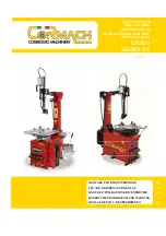
background image

TCE 4510

en

Repair instructions

Tyre changer

de

Instandsetzungsanleitung

Tyre changer

es

Instructions de réparation

Tyre changer

it

Istruzioni di riparazione

Tyre changer

Summary of Contents for TCE 4510

Page 1: ...TCE 4510 en Repair instructions Tyre changer de Instandsetzungsanleitung Tyre changer es Instructions de réparation Tyre changer it Istruzioni di riparazione Tyre changer ...

Page 2: ...1 695 104 941 2008 10 17 Robert Bosch GmbH 2 TCE 4510 ...

Page 3: ...1 695 104 941 2008 10 17 Robert Bosch GmbH TCE 4510 3 Inhaltsverzeichnis Deutsch 4 Contents English 18 Índice Español 32 Indice Italiano 46 ...

Page 4: ...hinweise und andere nützliche Informationen Einschrittige Handlungsaufforderung nur aus ei nem Schritt bestehende Handlungsaufforderung Zwischenergebnis innerhalb einer Handlungs aufforderung wird ein Zwischenergebnis sichtbar Endergebnis am Ende einer Handlungsaufforderung wird das Endergebnis sichtbar TCE 4510 1 2 Entsorgung Elektro und Elektronik Altgeräte einschließ lich Leitungen und Zubehör ...

Page 5: ...erung auswechseln Das selbstzentrierende Spannfutter lässt sich in kei ne der beiden Drehrichtungen drehen Sicherstellen ob der Stecker korrekt in die Steck dose eingesteckt wurde und sämtliche An schlüsse korrekt durchgeführt wurden Den Hauptschalter einschalten Umkehrpedal defekt austauschen Das selbstzentrierende Spannfutter dreht mit zu geringer Antriebskraft Sicherstellen ob die Netzspannung ...

Page 6: ...u 9 spannen die Schraube wieder einfügen und festziehen 10 die Einheit wieder in der Maschine positionieren 11 und die entsprechenden Befestigungsschrauben anziehen das Pedal wieder einbauen 12 die linke Schutzabdeckung schließen 13 die Stromversorgung wieder anschließen 14 Einstellung des Antriebriemens 3 3 Für die Einstellung des Riemens ist wie folgt vorzuge hen Die Stromversorgung unterbrechen...

Page 7: ... des Spannfutters der Kunststoffführungen und Austausch des Getriebegehäuses Kontrolle der korrekten Betriebsweise Ein beliebiges Rad in das Spannfutter einspannen 1 sicherstellen dass kein übermäßiges Spiel in Bezug 2 auf die Einspannung im Spannfutter vorhanden ist sollte ein übermäßiges Spiel der Vorrichtung festge stellt werden ist wie folgt vorzugehen die Maschine von der Stromversorgung tren...

Page 8: ...ungen ausgelöst daher sind der korrekte Spannungswert am Leitungseingang die Verbindungen innerhalb des Primärschaltkreises des Transformators und bei Austausch des Transformators die korrekte Stromstärke 1A zu überprüfen F6 Sicherung zum Schutz des Niederspannungs Sekundärschaltkreises des Transformators T 3 7 4 Diese Sicherung dient dem Schutz des Niederspannungsschaltkreises mit Gleichstrom 24V...

Page 9: ... Austausch des Umkehrpedals erforderlich sein wird auf den beiliegenden Schaltplan verwiesen um eine korrekte Wiederherstellung sämtlicher Anschlüsse gemäß den bereitgestellten Anweisungen zu gewährleisten In der Einphasen Ausführung stehen keine zwei Drehgeschwindigkeiten des Spannfutters zur Verfügung ...

Page 10: ...räts 3 7 7 Nach einer gewissen Stillstandszeit setzt das Steuergerät die Vorrichtung in Stand By um wieder in den normalen Betriebszustand zu wechseln genügt es einen beliebigen Bedienhebel mit zwei Positionen zu betätigen um die Pumpe wieder einzuschalten Um die Timerfunktion neu einzustellen muss der erste Trimmer Schalter auf Bw ge stellt werden werkseitig steht der erste Trimmer zwischen 1 bis...

Page 11: ...er elektrischen Anschlüsse verwiesen Q2 Magnetothermischer Motorschutzschalter für den Schutz des Motors der Hydraulikpumpe 3 7 11 Wird diese Sicherung ausgelöst müssen die Anschlüsse des Motors die Stromaufnahme des Motors und die kor rekte Kalibrierung der Vorrichtung in Abhängigkeit von den Motormerkmalen überprüft werden Sollte eine Umkehr der Drehbewegung des Motors erforderlich sein wird auf...

Page 12: ...herung ausgelöst wird ist zu überprüfen ob das Verbindungskabel der Pedal Einheit beschädigt ist und ob die Kabel im Innern durchgetrennt sind oder ein Kurzschluss an den Kabeln vorliegt bzw ob die Mi kroschalter der Pedal Einheit beschädigt sind was ebenfalls zu einem Kurzschluss führen kann Anschließend sind auch die beiden Fernschalter für die Drehbewegung der Spannfutterwelle insbesondere die ...

Page 13: ... Anschlüsse des Motors und die korrekte Stromaufnah me des Motors zu überprüfen F4 und F5 Sicherungen zum Schutz des Primärschaltkreises des Transformators T 3 8 3 Normalerweise werden diese Sicherungen bei Überspannungen ausgelöst daher sind der korrekte Spannungswert am Leitungseingang die Verbindungen innerhalb des Primärschaltkreises des Transformators und bei Austausch des Transformators die ...

Page 14: ...liegenden Schaltplan verwiesen um eine korrekte Wiederherstellung sämtlicher Anschlüsse gemäß den bereitgestellten Anweisungen zu gewährleisten Q4 Geschwindigkeitsumschalter 3 8 6 Wechselt von der ersten in die zweite Geschwindigkeit der Spannfutterwelle Bei Wiederherstellung der Anschlüs se sind die beiliegenden Informationen über die Anschlüsse zu berücksichtigen ...

Page 15: ...nd L liegt Die Leitung L und Nr 3 müssen hingegen die Abwärtsbewegung steuern indem das Magnetventil Y2B erregt wird das zwischen 3 und L liegt K1T Timer des Ölhydraulik Steuergeräts 3 8 8 Nach einer gewissen Stillstandszeit setzt das Steuergerät die Vorrichtung in Stand By um wieder in den normalen Betriebszustand zu wechseln genügt es einen beliebigen Bedienhebel mit zwei Positionen zu betätigen...

Page 16: ...hen 2 und L liegt Die Leitung L und Nr 1 müssen hingegen die Rückwärtsbewegung steuern indem das Magnetventil Y1N erregt wird das zwischen 1 und L liegt F1 F2 F3 Sicherungen zum Schutz des gesamten Hochspannungsschaltkreises 3 8 11 Sie gestatten die Versorgung des Primärschaltkreises des Spannungsumwandlers und des Motors für die Drehbe wegung der Spannfutterwelle Q3 Magnetothermischer Motorschutz...

Page 17: ...ng der Spannfutterwelle insbesondere die Spulen zu überprüfen Vergleichende Tabelle der 4 Hydrauliköle Falls im Zuge von Reparatureingriffen bei Ölaustritten Austausch von Komponenten etc das Nachfüllen von Hydrauliköl zur Wiederherstellung des erforderlichen Ölstandes notwendig sein sollte sind die Produkthin weise der nachfolgenden Tabelle zu berücksichtigen Typ Modell Normen Getriebeöl Texaco E...

Page 18: ...symbols are also used Single step procedure instructions for a procedure that can be completed in just one step Intermediate result an intermediate r esult is displayed during a procedure Final result the final result is displayed at the end of the procedure TCE 4510 1 2 Disposal Old electrical and electronic devices including cables and accessories or batteries must be disposed of separate to hou...

Page 19: ...nsion fuse is burnt replace The self centering chuck does not rotate in any direction Check the correct insertion of the plug and its connection Turn on the main switch Pedal inverter defective replace The self centering chuck turns with insufficient strength Check the correspondence of the mains tension with that shown on the registration plate Adjust the belt tightener see instructions Check the...

Page 20: ... a 180 rotation to charge the spring 9 Insert the spring and tighten it 10 Put again the inverter assembly in its position and 11 screw it inside the tyre changer Mount the pedal 12 Close the left cover 13 Connect power supply 14 Adjustment of the transmission belts 3 3 To adjust the belt Disconnect power supply 1 Remove the left closure cover 2 Open the counter nut on the motor support 3 Operate ...

Page 21: ...ent of the reducer gear Correct functioning check Mount a wheel on the self centering chuck 1 Check that there are no excessive plays on the self 2 centering chuck table If there are excessive plays of the device proceed as follows Disconnect power supply 3 Open the RT side door 4 Remove the self centering chuck 5 Extract the central shaft Unscrew the central locking nut with a 14mm long wrench Ex...

Page 22: ...ectrical surges so check that the mains supply tension is correct the connec tions on the primary circuit of the transformer itself and in case of replacement check that the amperage is correct 1A F6 protection fuse of the low tension circuit of the secondary of the T transformer 3 7 4 This fuse protects the low tension 24VDC direct current circuit In case of replacement check that the amperage is...

Page 23: ...23 en Q3 reverse gear 3 7 5 In case it is necessary to replace the inverter follow the shown diagram in order to restore correctly the connec tions along with the given information In the single phase version double speed of the self centering chuck is not available ...

Page 24: ... K1T hydraulic control panel timer 3 7 7 Puts the machinery in stand by after a certain period of inactivity of the control unit to start again normal func tioning press any of the two unstable positions control levers to make the pump run again If timer setting is nec essary place the function selector on Bw whereas by manufacturer default the first selector is on 1 10 min and the second one on 3...

Page 25: ...he protection of the hydraulic pump motor 3 7 11 If activated verify the connections of the motor its energy absorption and the correct calibration of the device according to the characteristics of the motor In case it is necessary to reverse the rotation direction of the motor follow the attached connection diagram F4 and F5 protection fuses of the primary circuit of the tension transformer T 100...

Page 26: ... and that the micro switches on the pedal box are not short circuited if they are damaged Finally check also the two remote control switches of the rotation mandrel specially the coils With this type of single phase machinery be very careful when operating on the motor condensers since they retain for a long time the residual electrical charge and therefore subsists the danger of electrical discha...

Page 27: ... motor connections and its correct electrical absorption F4 and F5 protection fuses of the primary circuit of the T transformer 3 8 3 They usually blow up in case of electrical surges so check that the mains supply tension is correct the connec tions on the primary circuit of the transformer itself and in case of replacement check that the amperage is correct 1A F6 protection fuse of the low tensi...

Page 28: ... 5 In case it is necessary to replace the inverter follow the shown diagram in order to restore correctly the connec tions along with the given information Q4 speed selector 3 8 6 Changes mandrel speed from first to second speed When restoring connections follow the connections shown below ...

Page 29: ... K1T hydraulic control panel timer 3 8 8 Puts the machinery in stand by after a certain period of inactivity of the control unit to start again normal func tioning press any of the two unstable positions control levers to make the pump run again If timer setting is nec essary place the function selector on Bw whereas by manufacturer default the first selector is on 1 10 min and the second one on 3...

Page 30: ...ctor for the protection of the motor and of the hydraulic pump 3 8 12 If activated verify the connections of the motor its energy absorption and the correct calibration of the device ac cording to the characteristics of the motor F4 and F5 protection fuses of the primary circuit of the tension transformer T 100VA 3 8 13 If the fuses burn usually because of a tension surge power supply will be miss...

Page 31: ...table below Type Model Standards Gearbox oil Texaco EP 460 ISO 460 DIN 51502 CLP ISO 34 98 CC Hydrau lic pump oil Esso Nuto H46 ISO 46 DIN 51502 HLP DIN 51524 PART 2 HLP ISO 67 43 HM Filter assembly oil Esso Febis K32 ISO 32 Suggested spare parts and 5 tools Tools which are essential for a correct maintenance A set of hex keys a 14 mm long hex key A screwdriver set slotted and Phillips A hex key s...

Page 32: ... i Indicaciones para la aplicación y otras informaciones útiles Instrucción de actuación paso a paso Instrucción de actuación compuesta por un solo paso Resultado intermedio Dentro de una instrucción de actuación se puede ver un resultado intermedio Resultado final Al final de una instrucción de actua ción se puede ver el resultado final TCE 4510 1 2 Eliminación Los aparatos eléctricos y electróni...

Page 33: ...mponente ver cap 3 Fusible baja tensión quemado sustituir El autocentrante no rueda en ningún sentido Verificar la correcta introducción del en chufe en la toma y su conexión Encender el interruptor general Inversor a pedal defectuoso sustituir El autocentrante gira con fuerza insuficiente Verificar la correpondencia entre la tensión de red y aquella indicada en la tarjeta del constructor Accionar...

Page 34: ...ación de 180 para poder cargar el 9 muelle Introducir el tornillo y apretarlo 10 Colocar nuevamente y ajustar el grupo inversor en 11 el interior de la desmontadora Montar el pedal 12 Cerrar el cárter izquierdo 13 Conectar la alimentación eléctrica 14 Regulación correa de transmisión 3 3 Para regular la correa Desconectar la alimentación eléctrica 1 Quitar el cárter de cierre izquierdo 2 Abrir la ...

Page 35: ...po reductor Control del correcto funcionamiento Montar una rueda cualquiera en el autocentrante 1 Controlar que no haya juegos excesivos sobre el 2 plano del autocentrante Si se notase un juego excesivo del dispositivo proseguir como se indica a continuación Desconectar el sistema eléctrico 3 Abrir la compuerta lateral dx 4 Desmontar el autocentrante 5 Remover el árbol central Desenroscar la tuerc...

Page 36: ... motor y la correcta absorción eléctrica del mismo F4 e F5 fusibles de protección del circuito primario del transformador T 3 7 3 Normalmente intervienen en casos de exceso de tensión por lo tanto se debe controlar el correcto voltaje en el ingreso a la línea las conexiones del circuito primario del mismo transformador y en el caso de sustitución verifi car el correcto amperaje 1A F6 Fusibles de p...

Page 37: ...ersor o del interruptor de 2 velocidades Si el defecto no desapare ce sustituir solo el motor Para proceder a la sustitución del motor seguir los esquemas eléctricos Q3 inversor de marcha 3 7 5 En el caso que haga falta la sustitución del inversor seguir el esquema dado para reiniciar correctamente las conexiones según las indicaciones En la versión monofase no está disponible la doble velocidad d...

Page 38: ...T Temporizador centralita oleodinámica 3 7 7 Después de un cierto tiempo de inactividad la centralita lleva a stand by el aparato para retomar el normal fun cionamiento pulsar cualquiera de los manipuladores a dos posiciones inestables para hacer arrancar la bomba Si fuese necesario resetear el timer ubicar el selector de función en Bw mientras que de fábrica el primer selector está en 1 10 min y ...

Page 39: ...bomba hidráulica 3 7 11 Si salta verificar las conexiones del motor la absorción del mismo y la correcta tara del dispositivo en base a las características del motor Si fuera necesario invertir el sentido de rotación seguir el esquema de conexión adjun to F4 e F5 Fusible de protección del circuito primario del transformador de tensión T 100VA 3 7 12 Si se queman normalmente a causa de un exeso de ...

Page 40: ... circuito que los micro interruptores de la pedalera no esten en corto circuito si se dañan Al final verificar también los dos telerruptores de la rotación del mandril en particular las bobinas Con este tipo de aparatos monofase prestar mucha atención cuando se opera en los condensadores de los motores eléctricos ya que conservan por largo tiempo la carga eléctrica residual con consiguiente peligr...

Page 41: ...del motor y la correcta absorción eléctrica del mismo F4 e F5 fusibles de protección del circuito primario del transformador T 3 8 3 Normalmente intervienen en caso de exceso de corriente por lo tanto se debe controlar el correcto voltaje de in greso en la línea las conexiones en el circuito primario del mismo transformador y en caso de sustitución verificar el correcto amperaje 1A F6 fusible de p...

Page 42: ... caso de ser necesaria la sustitución del inversor seguir el esquema dado para reiniciar correctamente las cone xiones según las indicaciones dadas Q4 conmutador de velocidad 3 8 6 Cambia de la primera a la segunda velocidad del mandril Al reanudar las conexiones seguir las conexiones abajo mencionadas ...

Page 43: ...temporizador centralita oleodinámica 3 8 8 Luego de un cierto tiempo de inactividad la centralita lleva a stand by el aparato Para retomar el normal funcio namiento pulsar cualquiera de los manipuladores en dos posiciones inestables para hacer arrancar la bomba Si fuese necesario resetear el timer ubicar el selector de función en Bw mientras de fábrica el primer selector está en 1 10min y el segun...

Page 44: ...a bomba hidráulica 3 8 12 Si salta verificar las conexiones del motor la absorción del mismo y la correcta tara del dispositivo en base a las características del motor F4 e F5 fusibles de protección del circuito primario del transformador de tensión T 100VA 3 8 13 Si se queman normalmente a causa de un exceso de tensión faltará la alimentación a todo el circuito de baja ten sión ya sea 24VDC ó 24V...

Page 45: ...r Texaco EP 460 ISO 460 DIN 51502 CLP ISO 34 98 CC Aceite bom ba hidráulica Esso Nuto H46 ISO 46 DIN 51502 HLP DIN 51524 PART 2 HLP ISO 67 43 HM Aceite gru po filtro Esso Febis K32 ISO 32 Recambios y herramientas 5 aconsejadas Instrumentos indispensables para una correcta asisten cia Juego de llaves octogonales en el interior brugola llaves octogonales en el interior brugola de 14 mm de largo Jueg...

Page 46: ...ndicazioni applicative ed altre informazioni utili Istruzioni rapide istruzioni costituite solo da una fase Risultato intermedio all interno di un istruzione è visibile un risultato intermedio Risultato finale al termine di un istruzione è visibile il risultato finale TCE 4510 1 2 Smaltimento Gli apparecchi elettrici ed elettronici fuori uso con relativi cavi accessori accumulatori e batterie devo...

Page 47: ...cap 3 Fusibile bassa tensione bruciato sostituire L autocentrante non ruota in alcun senso Verificare il corretto inserimento della spi na nella presa ed il suo collegamento Accendere l interruttore generale Invertitore a pedale difettoso sostituire L autocentrante gira con forza insufficiente Verificare la corrispondenza fra la tensione di rete e quella indicata sulla targhetta del costruttore Ag...

Page 48: ...0 in modo da caricare 9 la molla Inserire la vite e serrarla 10 Riposizionare nuovamente e avvitare il gruppo 11 invertitore all interno dello smontagomme Montare il pedale 12 Chiudere il carter sinistro 13 Collegare l alimentazione elettrica 14 Regolazione cinghia di trasmissione 3 3 Per registrare la cinghia Scollegare l alimentazione elettrica 1 Rimuovere il carter di chiusura sinistro 2 Aprire...

Page 49: ...rollo corretto funzionamento Montare una ruota qualsiasi sull autocentrante 1 Controllare che non ci siano giochi eccessivi sul pia 2 no dell autocentrante Se si dovesse notare un gioco eccesivo del dispositivo procedere come segue Scollegare l impianto elettrico 1 Aprire lo sportello laterale DX 2 Smontare l autocentrante 3 Sfilare l albero centrale Svitare il dado di bloccaggio centrale con una ...

Page 50: ...del motore e il corretto assorbimento elettrico dello stesso F4 e F5 fusibili di protezione del circuito primario del trasformatore T 3 7 3 Normalmente intervengono in caso di sovratensioni quindi controllare il corretto voltaggio in ingresso alla linea i collegamenti sul circuito primario dello stesso trasformatore e in caso di sostituzione verificare il corretto am peraggio 1A F6 fusibile di pro...

Page 51: ... dell interruttore 2 velocità Se il difetto non compare sostituire il solo motore Per procedere alla sostituzione del motore seguire gli schemi elettrici Q3 invertitore di marcia 3 7 5 Nel caso si renda necessaria la sostituzione dell invertitore attenersi allo schema riportato per ripristinare corretta mente i collegamenti secondo le indicazioni fornite Nella versione monofase non è disponibile l...

Page 52: ...con il numero 3 devono far muovere la discesa eccitando l elettrovalvola Y2B collegata tra 3 e L K1T temporizzatore centralina oleodinamica 3 7 7 Dopo un certo tempo di inattività della centralina porta in stand by l attrezzatura per far riprendere il normale fun zionamento premere uno qualsiasi dei manipolatori a due posizioni instabili per far ripartire la pompa Se si rend esse necessario il set...

Page 53: ...ma di collegamento allegato Q2 salvamotore magnetotermico per la protezione del motore della pompa idraulica 3 7 11 Se scatta verificare i collegamenti del motore l assorbimento dello stesso e la corretta taratura del dispositivo in base alle caratteristiche del motore Nel caso sia necessario invertire il senso di rotazione del motore seguire lo schema di collegamento allegato F4 e F5 fusibili di ...

Page 54: ...to circuito che i micro interruttori sulla pedaliera non siano in corto circuito se si danneggiano Infine verificare anche i due teleruttori della rotazione mandrino in particolare le bobine Con questo tipo di attrezzature monofase prestare molta attenzione quando si opera sui condensatori dei motori elettrici in quanto conservano per lungo tempo la carica elettrica residua con conseguente pericol...

Page 55: ...menti del motore e il corretto assorbimento elettrico dello stesso F4 e F5 fusibili di protezione del circuito primario del trasformatore T 3 8 3 Normalmente intervengono in caso di sovratensioni quindi controllare il corretto voltaggio in ingresso alla linea i collegamenti sul circuito primario dello stesso trasformatore e in caso di sostituzione verificare il corretto am peraggio 1A F6 fusibile ...

Page 56: ...da necessaria la sostituzione dell invertitore attenersi allo schema riportato per ripristinare corretta mente i collegamenti secondo le indicazioni fornite Q4 commutatore di velocità 3 8 6 Commuta dalla prima alla seconda velocità del mandrino Nel ripristinare i collegamenti attenersi ai collegamenti sotto riportati ...

Page 57: ...il 4 e il L invece il L con il numero 3 devono far muovere la discesa eccitando l elettrovalvola Y2B collegata tra 3 e L K1T temporizzatore centralina oleodinamica 3 8 8 Dopo un certo tempo di inattività della centralina porta in stand by l attrezzatura per far riprendere il normale fun zionamento premere uno qualsiasi dei manipolatori a due posizioni instabili per far ripartire la pompa Se si ren...

Page 58: ...tazione al circuito primario del trasformatore di tensione e al motore della rotazione mandri no Q3 salvamotore magnetotermico per la protezione del motore della pompa idraulica 3 8 12 Se scatta verificare i collegamenti del motore l assorbimento dello stesso e la corretta taratura del dispositivo in base alle caratteristiche del motore F4 e F5 fusibili di protezione del circuito primario del tras...

Page 59: ...olio attenersi a quanto riportato nella tabella sottos tante Tipo Modello Norme Olio per riduttore Texaco EP 460 ISO 460 DIN 51502 CLP ISO 34 98 CC Olio Pompa Idraulica Esso Nuto H46 ISO 46 DIN 51502 HLP DIN 51524 PART 2 HLP ISO 67 43 HM Olio Gruppo filtro Esso Febis K32 ISO 32 Ricambi e utensili consigli 5 ati Strumenti indispensabili per una corretta assistenza Set di chiavi a brugola chiave a b...

Page 60: ...Robert Bosch GmbH Diagnostics Franz Oechsle Straße 4 73207 Plochingen DEUTSCHLAND www bosch com bosch prueftechnik bosch com Printed in Germany Imprimé en Allemagne 1 695 104 941 2008 10 17 ...

Reviews: