background image

User and Installation manual

Electrical water storage tank

Tronic

6720816255-00.1V

ES 030 | 050 | 080 | 100 | 120...

6 720 816 255 (201

8/

06

) DIV

Summary of Contents for Tronic ES 030 Series

Page 1: ...User and Installation manual Electrical water storage tank Tronic 6720816255 00 1V ES 030 050 080 100 120 6 720 816 255 2018 06 DIV ...

Page 2: ... the appliance 9 5 3 Wall mounting 9 5 4 Water connection 10 5 5 Electrical connections 11 5 6 Start up 11 6 Use 12 6 1 Switching the appliance on off 12 6 2 Setting the DHW temperature 12 6 3 Draining the appliance 12 7 Environment disposal 13 8 Inspection Maintenance only for authorized technicians 14 8 1 User information 14 8 1 1 Cleaning 14 8 1 2 Safety valve verification 14 8 1 3 Safety valve...

Page 3: ...ried out by an authorised service IEC 60364 7 701 must be observed when installing the appliance and or electrical accessories The appliance must be installed in a room free from the risk of frost First connect the appliance hydraulically and fill with water then connect the power supply During the installation isolate the appliance from the power supply Warnings in this document are identified by...

Page 4: ...must only be carried out by an approved contractor Pointouttheneedforinspectionsand maintenance for safe and environmentally compatible operation The installation and operating instructions must be given to the user for keeping Safety of electrical appliances for domestic use and similar purposes The following requirements apply in accordancewithEN60335 1inorderto prevent hazards from occurring wh...

Page 5: ...ial steel sheeting and or plastic Easy handling Insulating material polyurethane without CFC Anticorrosion protection magnesium anode 2 4 Anticorrosion protection The inside of the tank is lined with homogeneous glass enamel completely neutral with regards to compatibility and contact with potable water This lining is neutral with regard to the use with potable water The existence of a magnesium a...

Page 6: ...1 20 2 20 5 23 7 24 0 27 4 Weight full kg 41 64 8 65 1 100 2 100 5 123 7 124 0 127 4 Water details Maximum permissible pressure bar 8 Water connections Pol 1 2 Electrical characteristics Nominal power W 1200 2000 1500 2000 1500 2000 1500 2000 Heating time T 50 C 1h16m 1h22m 1h43m 2h27m 2h46m 2h57m 3h47m 3h44m Voltage tension Vac 230 Frequency Hz 50 Monophasic electric current A 5 2 8 7 6 5 8 7 6 5...

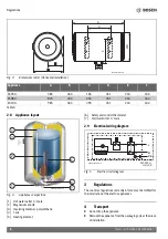
Page 7: ... in mm Vertical installation Appliance A B C D E F G ES030 447 433 225 451 165 100 to 280 240 ES050 610 433 370 451 165 100 to 280 240 ES080 857 433 580 451 165 100 to 280 240 ES100 1019 433 730 451 165 100 to 280 240 ES120 1182 433 905 451 165 100 to 280 240 Table 5 6720815708 01 1V F G ØB A C 9 D E 100 ...

Page 8: ...rical wiring diagram Fig 5 Electric circuit diagram 3 Regulations The country s regulations currentlyin forcemust be fulfilled for the installation of the electric appliances 4 Transport Do not drop the appliance Remove theappliance fromthe packagingonly at theplace of installation Appliance A B C D E F ES050 585 433 165 451 234 343 ES080 825 433 350 451 234 343 ES100 985 433 495 451 234 343 Table...

Page 9: ... maintenance procedures Protection area 1 Do not install in protection area 1 Install the appliance outside the protection area Fig 6 Protection areas 5 3 Wall mounting Installation power connection and commissioning must only be carried out by a service approved for such work by the local entities CAUTION Do not drop the appliance Remove the appliance from the packaging only at the place of insta...

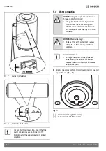
Page 10: ...om part of the appliance and in vertical position NOTICE Damage to appliance connections through contact corrosion Use galvanized insulators in your water connections These will avoid galvanic electric currents between the hydraulic link metals and consequently corrosion of these NOTICE Material damage Install a filter at the water inlet in areas where the water contains particles or sediments It ...

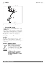
Page 11: ...r information of the appliance and handling Inordertoavoidproblemscausedbysudden pressure changes we recommend the installation of a non return valve at the appliance Fig 10 7 DANGER Install a safety valve at the water inlet of the appliance Fig 10 NOTICE NEVER OBSTRUCT THE PURGE OUTLET OF THE SAFETY VALVE Never install any accessory between the safety valve and the cold water inlet right hands si...

Page 12: ...ff the appliance from the electric supply Switchoff the water cutting valve and open a hot water tap Open the safety valve Fig 14 CAUTION The electrical connection must be done in accordance with the current domestic electrical compliance installation regulations Once the water has reached the selected temperature level the appliance stops heating up the indicator switches off When the water tempe...

Page 13: ...ng the environment taking into account of economic considerations Packaging We participate in the recycling programmes of the countries in which our products are sold to ensure optimum recycling All of our packaging materials are environmentally friendly and can be recycled Old electrical and electronic appliances Electrical or electronic devices that are no longer serviceable must be collected se...

Page 14: ...t breaker feeding the appliance Before starting verify that the appliance is disconnected from the electric current Completely drain the appliance section 6 3 Remove the lid of the appliance 1 by unscrewing the fixing screws Disconnect the connecting cables to the thermostat Unscrew the flange fastening screws remove the flange 2 Verifythemagnesiumanode 3 andreplaceitifnecessary Maintenance must o...

Page 15: ...m all the hot water taps Turn on the appliance to the electric current 8 3 Safety thermostat The appliance is equipped with an automatic safety thermostat If for any reason the water temperature inside the appliance exceeds the safety limit the switch will trigger and cut all electric current supplying the appliance thus avoiding any accidents Fig 16 Reset button 8 4 Requiredactionsafteranymainten...

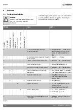
Page 16: ...e device X X Incorrecttemperatureregulatingthrough the thermostat Regulate the thermostat X Thermostat temperature safety active Replace or re install the thermostat X Damaged heating element Replace the heating element X Incorrect functioning of the thermostat Replace or re install the thermostat X X X X Device incrustation and or from the safety group Perform a descaling of the appliance If nece...

Page 17: ...17 Tronic 6 720 816 255 2018 06 Notes ...

Page 18: ...18 Tronic 6 720 816 255 2018 06 Notes ...

Page 19: ...19 Tronic 6 720 816 255 2018 06 Notes ...

Page 20: ...Bosch Thermotechnik GmbH Junkersstrasse 20 24 D 73249 Wernau www bosch thermotechnology com ...

Reviews: