background image

Form No. MSC11073 Rev B

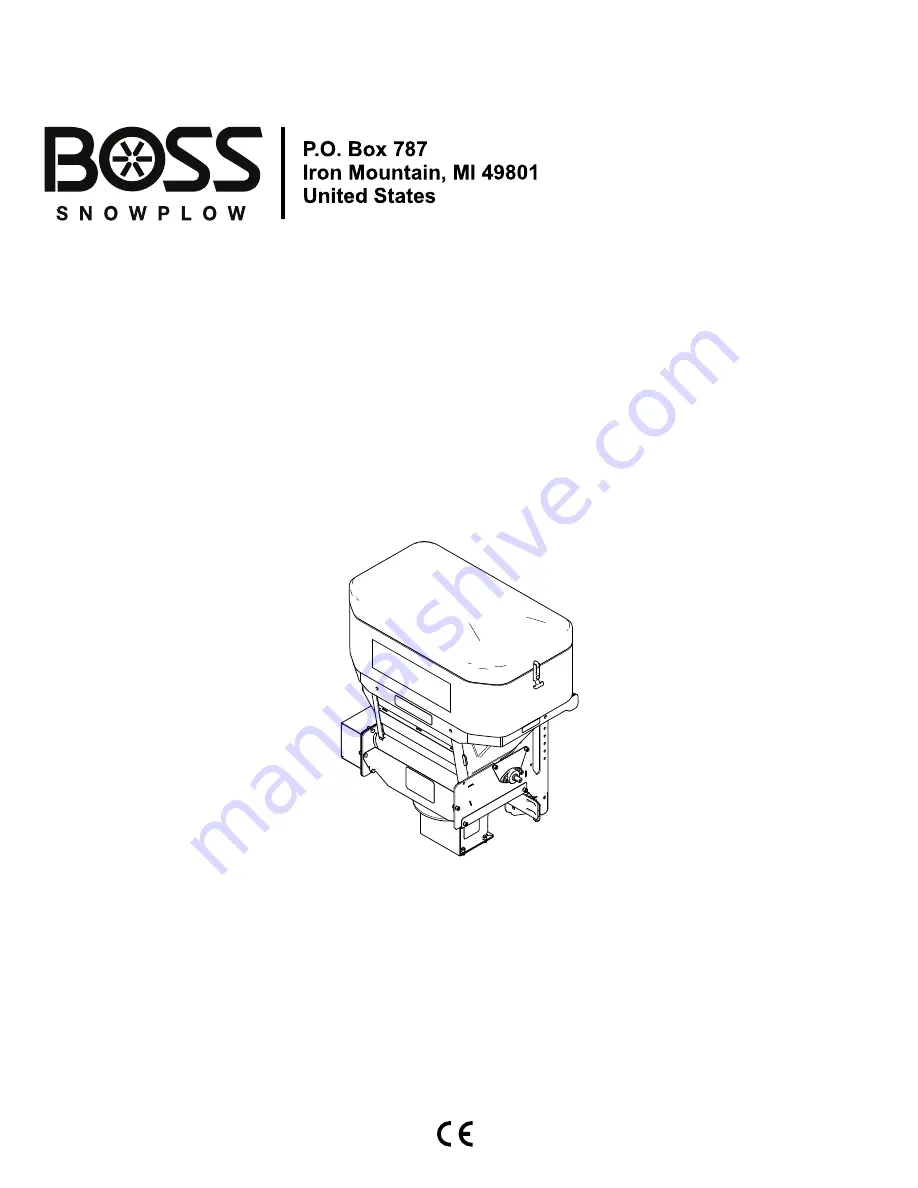
Owner's Manual

TGS 800 Tailgate Spreader

Part No. TGS08000—Serial No. 400000000 and Up

Part No. TGS11072—Serial No. 400000000 and Up

Register at www.bossplow.com.
Original Instructions (EN)

*MSC11073*


Summary of Contents for TGS 800

Page 1: ...o MSC11073 Rev B Owner s Manual TGS 800 Tailgate Spreader Part No TGS08000 Serial No 400000000 and Up Part No TGS11072 Serial No 400000000 and Up Register at www bossplow com Original Instructions EN MSC11073 ...

Page 2: ...ler or to register your product Whenever you need service genuine BOSS parts or additional information contact an Authorized BOSS Dealer or BOSS Technical Service 1 800 286 4155 and have the model and serial numbers of your product ready Figure 1 identifies the location of the model and serial numbers on the product Write the numbers in the space provided g031005 Figure 1 1 Serial number location ...

Page 3: ...result in injury To reduce the potential for injury comply with these safety instructions and always pay attention to the safety alert symbol which means Caution Warning or Danger personal safety instruction Failure to comply with the instruction may result in personal injury or death Preparation Ensure that only trained personnel install and perform maintenance on the equipment Always wear approp...

Page 4: ...preader Do not attempt to mount or remove the spreader with material in it Turn the spreader off before filling mounting removing servicing or cleaning it Never operate the spreader within 7 6 m 25 ft of bystanders Do not climb into or ride on the spreader Keep your hands feet and clothing away from moving parts and mounting points Mount the spreader to a vehicle before loading material Install ra...

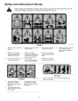
Page 5: ...operating the machine 5 Warning empty the hopper and disconnect the power before installing or removing the machine 8 Warning the machine must be installed before filling 3 Loss of control hazard do not overfill the machine 6 Thrown object hazard keep bystanders away from the machine 9 Warning do not store materials in the machine decaltgs05895b TGS05895 1 Cutting dismemberment hazard auger keep f...

Page 6: ...2 Coupler spring pin unlock 5 Coupler spring pin lock 3 Coupler spring pin unlock position 6 Coupler spring pin lock position decaltgs05896 TGS05896 1 Important read the Owner s Manual 2 The lock pin must be fully engaged before using the machine decalmsc06370 MSC06370 non replaceable decal 1 Feeder speed 4 Vibrator 2 Power 5 Blast 3 Lights 6 Spinner speed 6 ...

Page 7: ...he engine compartment and secure it with cable ties Note Keep the wire harness away from any hot or moving parts 3 Insert the controller connectors spade connector and ground cable through the firewall and into the vehicle cab and secure them with cable ties Note Route the connectors to the location that you want to install your controller 4 Connect the black ring connector in the engine compartme...

Page 8: ...sher 1 2 inch 2 Ratchet strap 4 Bolt 1 2 inch 2 Slide the hitch on the spreader into the receiver hitch of your vehicle and line up the second hole on the spreader hitch with the hole in the hitch of your vehicle Figure 6 Note If the spreader contacts the bumper of your vehicle slide the spreader out and align the first hole of the spreader hitch instead DANGER The spreader is heavy and could caus...

Page 9: ...ting bolts 3 8 inch and locknuts 3 8 inch and torque the bolts to 27 Nm 19 7 ft lb as shown in Figure 8 Mounting the Spreader with the RT3 Attachment 1 Attach the D ring end of the ratchet straps to the upper holes on the outside of the spreader frame using a bolt 1 2 inch washer 1 2 inch and locknut 1 2 inch and torque the bolts to 76 Nm 56 ft lb as shown in Figure 9 g234640 Figure 9 1 Locknut 1 ...

Page 10: ...e Ensure that the top pin of the RT3 attachment is fully locked into place and that the safety latch is down 8 Attach the stabilizer arms to the spreader frame using 8 bolts 3 8 inch and 8 locknuts 3 8 inch and torque the bolts to 27 Nm 19 7 ft lb as shown in Figure 7 Note Attach the arms so that the stabilizer pads contact your truck bumper 9 Rotate the pads on the stabilizer arms until they are ...

Page 11: ... Attach the mounting bracket to the vehicle using 2 sheet metal screws Figure 14 g239094 Figure 14 1 Thumb screw 3 Mounting bracket 2 Star washer 4 Sheet metal screw 2 Attach the controller to the mounting bracket using 4 star washers and 2 thumb screws Figure 14 Note Position the controller screen so that it is clearly visible to the driver 3 Connect the wire harness controller connectors to the ...

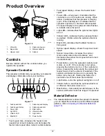
Page 12: ...s Light LED indicates that the optional rear lights are on Vibrator LED indicates that the optional vibrator is enabled It blinks while the optional vibrator is running Blast LED indicates that the Blast function is being used Spinner speed display shows the spinner motor speed Spinner speed dial increases the spinner motor speed when turned clockwise and decreases the spinner motor speed when tur...

Page 13: ...Note Specifications and design are subject to change without notice Hopper height 66 cm 26 inches Hopper width 91 cm 36 inches Hopper depth 53 cm 21 inches Spreader weight empty 100 kg 220 lb Capacity 0 3 m3 11 ft3 13 ...

Page 14: ... the stabilizer arms until they are tight against your truck bumper and tighten the jam nut to secure them 5 Slide the ends of the ratchet straps between the bumper and tailgate on your vehicle and attach them to a solid point on the truck frame rail 6 Remove the weather caps from both the vehicle and spreader wire harnesses and plug the spreader harness into the vehicle wire harness Removing the ...

Page 15: ...eavy and could cause serious injury or property damage if it falls off your vehicle Ensure that the top pin of the RT3 attachment is fully locked into place and that the safety latch is down 6 Rotate the pads on the stabilizer arms until they are tight against your truck bumper and tighten the jam nut to secure them 7 Slide the ends of the ratchet straps between the bumper and tailgate on your veh...

Page 16: ... area Loading the Spreader Important Only use dry sand salt or a sand salt mixture in the spreader Other materials could cause damage to the machine 1 Ensure that the spreader is securely mounted to your vehicle and is not over slippery or uneven terrain 2 Remove the hopper cover and ensure that the top screen is installed and closed 3 Determine the amount of material that you can safely transport...

Page 17: ...rease the speed of the spinner and feeder motors 6 Press the Power button when you are finished spreading to stop the spreader 7 Press and hold the Power button for 3 seconds or turn off your vehicle to turn off the spreader controller Freeing a Clog The red LED on the spreader controller illuminates when debris gets wedged in the spreader and the controller is overloaded If the clog is not cleare...

Page 18: ...n adjust the spread pattern by positioning the deflectors as shown in Figure 29 g029499 Figure 29 Deflection Settings 1 Driver side open 3 Both sides open 2 Passenger side open Adjusting the Rubber Flaps The rubber flaps on the spreader wear down over time and must be adjusted 1 Ensure that the spreader controller is in the OFF position and unplug the spreader wire harness from the vehicle wire ha...

Page 19: ...n of the spreader g186473 Figure 31 1 Plate 4 Tighten the loosened bolts 5 Install the previously removed top screen and hopper cover Operating Tips Know the area in which you are working hidden obstructions such as curbs sidewalks manhole covers and pipes can damage your spreader or vehicle Do not let the ice build up always start as soon as possible Always wear your seatbelt when spreading Alway...

Page 20: ...en as necessary Every 20 hours Clean the chute of any buildup Grease the bearings Tighten the hardware Before storage Unload the spreader Clean and grease all of the bearings Lubrication Greasing the Machine Every 20 hours Grease the bearings Grease all of the bearings with a No 2 lithium grease Storage 1 Unload the spreader refer to Unloading the Spreader page 17 2 Remove the spreader from the ve...

Page 21: ... LED is red 3 The spinner motor is not connected to the spreader side harness 3 Connect the wire harnesses 1 The spreader and vehicle wire harnesses are not connected 1 Connect the wire harnesses 2 The controller is not plugged into the vehicle wire harness 2 Plug in the controller The feeder motor does not work 3 The feeder motor is not connected to the spreader wire harness 3 Connect the wire ha...

Page 22: ...Notes ...

Page 23: ...Notes ...

Page 24: ......

Reviews: