background image


OPERATING MANUAL  
ELECTROSURGICAL UNIT 


Summary of Contents for ARC 400

Page 1: ...OPERATING MANUAL ELECTROSURGICAL UNIT ...

Page 2: ...2 Operating Manual ARC 400 900 400_IFU_V1 0 0 6 17 9_20140 S2 20130604 EN ...

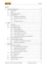
Page 3: ...ree patient positioning 12 2 3 4 Correct connection of the HF device 12 2 3 5 Correct use of the HF device 12 2 3 6 Configuring HF device settings and using accessories 13 2 4 Product related safety instructions 14 2 5 Safe handling general instructions 14 2 5 1 Operation area avoiding ignition and explosions 15 2 5 2 Applying the neutral electrode 15 3 Description 18 3 1 User interface components...

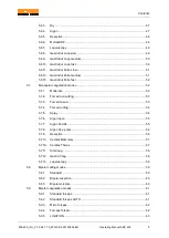
Page 4: ...7 4 5 1 General information 27 4 5 2 EASY neutral electrode monitoring EASY monitoring 28 5 Operation 29 5 1 Connecting power 29 5 2 Program overview 29 5 2 1 Display 29 5 2 2 Status bar 30 5 3 Activating and deactivating connectors 30 5 4 Configuring output currents 31 5 4 1 Selecting the mode 31 5 4 2 Specifying power limits 32 5 4 3 Selecting the effect 33 5 4 4 Assigning the foot pedal 34 5 4 ...

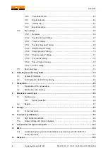
Page 5: ...tion modes 52 5 7 1 Moderate 52 5 7 2 Forced non cutting 53 5 7 3 Forced mixed 53 5 7 4 Forced cutting 54 5 7 5 Spray 54 5 7 6 Argon open 55 5 7 7 Argon flexible 55 5 7 8 Argon flex pulse 56 5 7 9 Resection 56 5 7 10 Cardiac Mammary 57 5 7 10 Cardiac Thorax 57 5 7 11 SimCoag 58 5 7 12 Gastro Coag 58 5 7 13 Laparoscopy 59 5 8 Bipolar cutting modes 59 5 8 1 Standard 59 5 8 2 Bipolar resection 60 5 8...

Page 6: ...dialog 72 5 10 10 Argon dialog 73 5 11 Basic programs 74 6 Detecting and correcting faults 79 6 1 System informations 79 6 2 Fault indications for EASY monitoring 84 7 Preparation 85 7 1 Preparation of the accessories 85 7 2 Disinfection and cleaning 85 8 Maintenance and repair 86 8 1 Maintenance 86 8 1 1 Safety inspection 86 8 2 Repairs 87 9 Storage 88 9 1 Technical service 88 10 Technical specif...

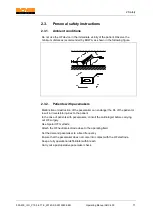
Page 7: ...eep the operating manual accessible to operating room personnel Give the operating manual to each successive owner and or user of this device Always update the operating manual whenever you receive additional information from the manufacturer 1 1 Revision index Unit version Last revised Valid from version 1 0 0 6 17 9 2013 06 1 2 Validity This operating manual applies only to the devices designate...

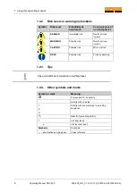
Page 8: ...s WARNING Possible risk Death serious injuries CAUTION Possible risk Minor injuries NOTE Possible risk Property damage 1 4 3 Tips Tips and additional information to facilitate tasks 1 4 4 Other symbols and marks Symbol or mark Meaning Prerequisite for an activity Activity with one step 1 2 3 Activity with several steps in a binding sequence Result of preceding activity List first level List second...

Page 9: ...al resection TUR Do not use the HF device if in the opinion of an experienced physician or according to current professional literature such use would endanger the patient due for example to the general condition of the patient or if other contraindications are present BOWA requires that the HF device is operated under the supervision of qualified and authorized personnel The surgeon and medical s...

Page 10: ...atisfy relevant IEC or ISO standards e g IEC 60950 for data processing devices Furthermore all configurations must comply with the standardised requirements for medical systems see IEC 60601 1 1 or Section 16 of the 3rd edition of IEC 60601 1 as relevant Anyone who connects additional devices to electrical medical devices is automatically a system configurator and thus responsible for meeting stan...

Page 11: ...alfunction or destruction of the pacemaker can endanger the life of the patient or result in irreversible injuries to the patient In the case of patients with pacemakers consult the cardiologist before carrying out HF surgery Use bipolar HF methods Attach the HF neutral electrode close to the operating field Set the demand pacemaker to a fixed frequency Ensure that the pacemaker does not come into...

Page 12: ... away from the HF electrodes as possible Place lines from monitoring devices so that they do not lie on the patient s skin Keep the leads to the HF electrodes as short as possible and position them so that they do not touch the patient or other leads Do not place any objects on the HF device 2 3 5 Correct use of the HF device Inadvertent activation of the HF device outside the user s field of visi...

Page 13: ...ted so that it is always clearly audible Risk of nerve or muscle excitation by low frequency currents During HF surgical operations especially when an arc is formed part of the HF current is converted into a low frequency current This current can trigger muscle contractions in the patient To minimize the risk of injury to the patient set the power and the effect as low as possible Correct use of a...

Page 14: ...ect it mechanically If any fluids penetrate the device drain them immediately Damage to the device can lead to an undesirable increase in output power due to improper operation of the device Certain units or accessories can cause danger in lower power settings For example the risk of gas embolism in argon assisted coagulation rises if the hf power is insufficient for the fast creation of an impene...

Page 15: ...e that no flammable liquids collect beneath the patient or in body cavities e g the vagina Suction and or flush body cavities before activating the device Wipe off all liquids before using the HF device Ensure that no ignitable endogenous gases are present Ensure that all materials saturated with oxygen e g cotton or gauze are kept far enough away from the HF environment that they cannot ignite 2 ...

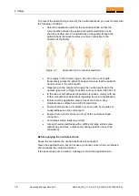
Page 16: ...e nearest upper arm or thigh if possible but never closer than 20 cm In the case of self adhesive disposable electrodes comply with any further manufacturer instructions regarding the point of application Ensure that the application area is free of scar tissue bony protuberances surface hair and ECG electrodes Ensure that there are no implants e g bone nails bone plates or endoprostheses in the cu...

Page 17: ...de Remove the protective film and attach the self adhesive disposable electrode to the patient Ensure that the long edge of the disposable electrode faces the operation site and the electrode is fully in contact with the skin This avoids excessive current concentration on the short edge Using both hands press the self adhesive disposable electrode firmly against the patient s skin Clamp the electr...

Page 18: ...r upper monopolar socket 6 Activation bar lower monopolar socket 7 Activation bar upper bipolar socket 8 Activation bar lower bipolar socket While activating an instrument the activation bar of the corresponding socket illuminates yellow or blue 3 1 2 Monopolar connector module left 9 Socket connector for monopolar instruments with hand or foot switch 10 Socket connector for monopolar instruments ...

Page 19: ...t switch 14 4 mm socket for foot switch Version 2 12 3 pin US type 13 Erbe 5 mm 14 4 mm socket for foot switch Connection socket for neutral electrode 15 Neutral US type 3 1 3 Bipolar connector module right 16 Socket connector for bipolar instruments with foot switch or AUTOSTART 17 Socket connector for bipolar instruments with foot switch or AUTOSTART 12 13 14 15 16 17 ...

Page 20: ... switch socket connector 1 21 Foot switch socket connector 2 22 Equipotential bonding terminal 23 IEC power cord connector 24 Fiber optic signal input connector 25 Fiber optic signal output socket connector Use the following connections only for service and training purposes 26 Ethernet connector 27 USB connector 28 Audio In not occupied 29 UART communication interface The USB connector can be use...

Page 21: ...ng activation of the HF device RF energy in the radio frequency range 9 kHz to 400 GHz is applied which produces electromagnetic radiation Labeling of electrical and electronic devices in accordance with Directive 2002 96 EC WEEE see Disposal Active HF output caution hazardous voltage Manufacturer Date of manufacture Observe use instructions Equipotentiality connection Fiber optic signal input Fib...

Page 22: ...he current catalogs 3 4 Components required for operation Power cable Foot switch Neutral electrode for monopolar applications Connection cable for neutral electrode or instrument Instrument monopolar or bipolar Dr Dongle as an individual memory stick 3 5 Operating conditions Temperature 10 C to 40 C Relative humidity 30 to 75 non condensing Atmospheric pressure 700 to 1600 hPa Operating altitude ...

Page 23: ...patient see section Ambient conditions page 11 HF devices may be used only in rooms used for medical purposes that meet the requirements of DIN VDE 0100 710 If the HF device was previously stored or transported at temperatures below 10 C it will take approximately three hours to adjust to room temperature 1 Observe the specified operating conditions see Section Operating conditions page 22 2 Place...

Page 24: ...icators for proper operation Power switch Touchscreen Monopolar socket connectors Bipolar socket connectors Activation bar for monopolar and bipolar sockets The main screen appears and the HF device is ready for use The parameters of the most recently selected program appear on the display 4 3 Connecting instruments Before connecting instruments ensure that the following conditions are met Combina...

Page 25: ...ar cable to one of the two bipolar socket connectors 3 For bipolar use without AUTOSTART connect a footswitch to the socket connector or Use the AUTOSTART mode for the appropriate socket connector Once the instrument is connected the application starts after the configured delay time 4 3 3 Connecting a foot switch In addition to the manual switch a foot switch can be used to activate various opera...

Page 26: ...SY neutral electrode indicator changes to green 2 Remove the neutral electrode The indicator changes to red acoustic signals sound The neutral electrode used for this test may not later be used for an operation 3 Connect a monopolar HF handpiece to a monopolar socket connector if there is a green EASY indicator and use the manual switch and footswitch to individually activate Cut and Coag 4 Check ...

Page 27: ... Service department see Section Technical service page 88 The HF device can be switched off at any time by using on off switch as an emergency stop switch 4 5 Neutral electrode monitoring Always use the largest possible electrode when attaching a neutral electrode 4 5 1 General information BOWA recommends using split neutral electrodes since only this type of electrode allows the HF device to dete...

Page 28: ...nd audible alarms to request staff intervention This requires using a split neutral electrode with appropriate contact areas and suitable contact resistance attached to the patient according to the manufacturer s instructions The EASY system does not monitor the currents through the individual contact surfaces of the split neutral electrode An electrode with a surface area of at least 110 cm must ...

Page 29: ...tionality of the loudspeaker is indicated by the start melody The individually configurable start screen appears if it has been set up 5 2 Program overview 5 2 1 Display Figure 5 1 Main screen The status bar is located at the top of the display The settings of the four socket connectors are shown below the status bar Settings can be configured for each of the connectors The Effect button is used t...

Page 30: ...Activating and deactivating connectors To activate a deactivated socket connector plug a connecting cable into the connector or Press the activate socket button An overview of the connector settings appears Figure 5 4 Deactivated socket The overview is grayed out if no instrument is connected to the socket connector Figure 5 5 Unused socket The socket illumination extinguishes and connector lights...

Page 31: ... 5 7 Modes monopolar cutting 1 To select the type of current for monopolar cutting first select one of the two socket connectors on the left side 2 Press the yellow icon under the Mode button A selection screen appears for the available modes and the rim of the associated connector starts blinking 3 Select the desired mode by pressing the corresponding button or Deactivate the mode by pressing the...

Page 32: ... and then back again the user changes are not undone 5 4 2 Specifying power limits Figure 5 8 Power limit monopolar cutting 1 To select the maximum current for monopolar cutting first select one of the two socket connectors on the left side and press the yellow icon under the max Watt button 2 Use the and buttons to adjust the power level in single steps or Use the slider to set the power level in...

Page 33: ...t select one of the two socket connectors on the left side and press the yellow icon under the Effect button 2 Use the and buttons to adjust the effect in individual steps or Use the slider to set the effect 3 Press the button for more information on this selection 4 Confirm your selection by pressing the OK button or Press the back button to return to the main screen without changing the selectio...

Page 34: ...ing the button Pedal 2 Select the desired foot switch by pressing the corresponding button For example choose the active pedal level for cutting and coagulation of the upper left socket or Deactivate the foot switch by pressing the button marked with a x The edge of the selected button lights up green 3 Confirm the selection by pressing the OK button or Press the Back button to return to the main ...

Page 35: ...20130604 EN Operating Manual ARC 400 35 Figure 5 11 Foot switch changeover If two footswitches are connected either a single pedal footswitch or a double pedal footswitch can be selected for coagulation Figure 5 12 Foot switch selection coagulation ...

Page 36: ...iption Double pedal foot switch CUT active Double pedal foot switch COAG active Double pedal foot switch CUT inactive Double pedal foot switch COAG inactive Double pedal foot switch not connected Double pedal foot switch not connected Single pedal foot switch COAG active Single pedal foot switch not connected Single pedal foot switch COAG inactive Deactivate foot switch ...

Page 37: ...lower bipolar socket can only be used with two bipolar ERBE plugs The AUTOSTART mode is not available if the socket is split 1 Use the mode selection for cutting of the lower bipolar socket Figure 5 13 Mode change 2 To change the mode to coagulation touch the Mode change button Now three bipolar connections are at your disposal An indicator of the mode change is shown next to the button Effect Fig...

Page 38: ...sponding icon EASY for monitoring split neutral electrodes BABY for monitoring split neutral electrodes for infants MONO to select a one piece neutral electrode 3 Press the button for more information on this selection 4 Confirm your selection by pressing the OK button or Press the Back button to return to the main screen without changing the selection The selected type of neutral electrode in con...

Page 39: ...eutral electrode contact quality not optimum Non split neutral electrode not detected or contact quality insufficient Split neutral electrode contact quality insufficient Non split neutral electrode not connected recognised Split neutral electrode not connected recognised Display contact quality Split baby neutral electrode contact quality OK Split baby neutral electrode contact quality not optimu...

Page 40: ...bsequent use Insert your Dr Dongle with your personal settings into every ARC 400 at any bipolar socket The data is read as soon as you insert Dr Dongle or after changing a program with Dr Dongle inserted Figure 5 16 COMFORT function detected After a short loading period an overview of the saved programs appears automatically as a new user interface Figure 5 17 Dr Dongle program selection ...

Page 41: ...e and re insert Dr Dongle The aforementioned steps 1 4 can now be repeated Load a program from Dr Dongle A program saved on Dr Dongle can be loaded onto any ARC 400 1 Select a program saved on Dr Dongle from the overview by touching the program name 2 Press load to load the selected program or Press back to return to the main screen without carrying out changes to the selection The selected progra...

Page 42: ...is connected to a socket with preset parameters a plausibility check is carried out The preset values for the COMFORT instrument are not overwritten if they are within a permissible range The COMFORT instrument can now be used with the preset parameters or Press OK to accept the selection Press back to return to the main screen without carrying changes to the selection The COMFORT instrument can n...

Page 43: ...eichen Modus Schneiden Bezeichnung Bildzeichen Modus Koagulieren Bezeichnung Standard Moderate Micro Forced non cutting Dry Forced mixed MetraLOOP Forced cutting Resection Spray Laparoscopy Laparoscopy Argon Argon open GastroCut Loop slow Argon flexible GastroCut Loop medium Argon flex pulse GastroCut Loop fast Gastro Coag These modes can only be used in connection with the argon coagulation unit ...

Page 44: ...900 400_IFU_V1 0 0 6 17 9_20140 S2 20130604 EN Bildzeichen Modus Schneiden Bezeichnung Bildzeichen Modus Koagulieren Bezeichnung GastroCut Knife slow Resection GastroCut Knife medium Cardiac Mammary GastroCut Knife fast Cardiac Thorax SimCoag ...

Page 45: ...LUS Bipolar scissors Laparoscopy Bipolar resection The information and data regarding settings application points application duration and instrument use are based on clinical practice However these are only basic guidelines which must be tested for suitability by the operator Depending on individual conditions it may be necessary to deviate from the provided data Medical practice is continuously ...

Page 46: ...sue type and changes in the cutting area or speed Application areas Cutting tissue with low electrical resistance such as muscle tissue or vascular tissue Cutting or preparing fine structures Suitable instruments Needle electrodes Knife electrodes Spatula electrodes Sling electrodes 5 6 2 Micro This mode is used for electrosurgical cutting using micro electrodes It enables extremely fine control o...

Page 47: ...iac surgery and blood coagulation in retracting blood vessels in the sternum region Suitable instruments Knife electrodes 5 6 4 Argon This mode is used to perform open surgical interventions in combination with the ARC PLUS companion device for argon assisted cutting With suitable instruments connected argon assisted cutting can be performed using rigid electrodes Application areas Visceral surger...

Page 48: ...fluids Application areas Hysteroscopy transurethral prostate resection TUR P surgical treatment of bladder tumors TUR B vaporization of prostate tissue TUR VAP Suitable instruments Resectoscope monopolar Resection sling Rollerblade electrode 5 6 6 MetraLOOP This mode is used in gynecology for laparoscopic hysterectomy Removal of the uterus can be achieved by applying monopolar cutting current and ...

Page 49: ... slow This mode is used in gastroenterology Polypectomy snares are used for cutting and coagulation ARC control generates the cutting effect with simultaneously minimized output power This mode consists of a series of cutting current pulses followed by a coagulation phase With a relatively slow pulse rate of 1 cutting pulse per second this mode is suitable for especially cautious work Application ...

Page 50: ...val using polypectomy snares and flexible endoscopy with accelerated pulse rate for experienced users Suitable instruments Polypectomy snares 5 6 10 GastroCut Loop fast This mode is used in gastroenterology Polypectomy snares are used for cutting and coagulation ARC control generates the cutting effect with simultaneously minimized output power This mode consists of a series of cutting current pul...

Page 51: ...pillotome and flexible endoscopy resection with needle knives slow pulse rate for cautious work Suitable instruments Papillotome Needle knives 5 6 12 GastroCut Knife medium This mode is used in gastroenterology Instruments for papillotomy and endoscopic resections are used for cutting and coagulation ARC control generates the cutting effect with simultaneously minimized output power This mode cons...

Page 52: ...ndoscopy resection with needle knives accelerated fast pulse rate for advanced users Suitable instruments Papillotome Needle knives 5 7 Monopolar coagulation modes 5 7 1 Moderate This mode is used with contact coagulation to stop hemorrhagic oozing for hemostasis of relatively large tissue areas and for small area coagulation Tissue carbonization is prevented and electrode adhesion to the tissue i...

Page 53: ...reas Fast coagulation with small penetration depth Suitable instruments Ball electrodes Knife electrodes Spatula electrodes 5 7 3 Forced mixed This mode is used for contact coagulation with low tissue penetration preferably using fine electrodes and electrodes with small contact areas It achieves a high degree of coagulation with moderate cutting tendency Application areas Fast coagulation with sm...

Page 54: ...y Application areas Fast coagulation with small penetration depth and very good cutting tendency Suitable instruments Knife electrodes Spatula electrodes Needle electrodes 5 7 5 Spray This mode is used with non contact surface coagulation using an arc for hemostasis in parenchymal tissue in poorly accessible crevices and in conjunction with argon coagulation Application areas Promoting coagulation...

Page 55: ...rgon assisted coagulation can be performed using rigid electrodes Application areas Visceral surgery Suitable instruments Rigid argon electrodes Argon handpiece 5 7 7 Argon flexible This mode is used for argon assisted electrosurgery in conjunction with the ARC PLUS accessory device This is the current type Spray For argon assisted coagulation flexible probes are used in combination with endoscope...

Page 56: ...nges with the effect setting The higher the effect level the faster the pulse sequence Application areas Gastroenterology homogeneous surface coagulation Suitable instruments Flexible argon probes 5 7 9 Resection This mode is used for monopolar hemostasis in gynecology and urology Use non conductive irrigation fluids Application areas Hysteroscopy transurethral prostate resection TUR P surgical tr...

Page 57: ...d in mammary surgery and cardiac surgery It produces forced coagulation Application areas Mammary surgery and cardiac surgery Suitable instruments Knife electrodes 5 7 10 Cardiac Thorax This mode is used in thoracic surgery It produces forced coagulation Application areas Thoracic surgery Suitable instruments Knife electrodes ...

Page 58: ...fect 1 Forced cutting Effect 2 Forced mixed Effect 3 Spray The output power setting applies to both output sockets and the power is distributed according to the tissue structure Application areas Simultaneous coagulation and preparation e g for cardiac or mammary surgery Suitable instruments Ball electrodes Knife electrodes Spatula electrodes 5 7 12 Gastro Coag This mode is used in gastroenterolog...

Page 59: ...d arthroscopy for monopolar coagulation Application areas Laparoscopy arthroscopy Suitable instruments Arthroscopy electrodes Laparoscopy electrodes 5 8 Bipolar cutting modes 5 8 1 Standard This mode is used for cutting with bipolar laparoscopic instruments Application areas Laparoscopic cutting Suitable instruments Laparoscopic instruments ...

Page 60: ...ntinuous activations Application areas Hysteroscopy transurethral prostate resection TUR P surgical treatment of bladder tumors TUR B vaporization of prostate tissue TUR VAP Suitable instruments Resectoscope bipolar Resection sling Rollerblade electrode Optimum results are provided exclusively when using BOWA COMFORT resection cables 5 8 3 Bipolar scissors This mode is used with bipolar scissors I...

Page 61: ... forceps 5 9 2 Standard forceps AUTO This mode is used for arcless contact coagulation with forceps Activation starts automatically on contact with tissue The adjustable delay time can be set under MENU SYSTEM SETTINGS AUTOSTART DELAY Setting the AUTOSTART mode can result in unintentional coagulations e g when bipolar forceps are used for gripping while the AUTOSTART Mode is on Application areas B...

Page 62: ...control of power output down to 0 1 W and precise work for tightly restricted bipolar contact coagulation Application areas Bipolar coagulation in pediatric surgery neurosurgery plastic surgery etc Suitable instruments Bipolar forceps Micro forceps 5 9 4 Forceps forced This mode is used for forced coagulation with forceps Application areas Fast bipolar coagulation Suitable instruments Bipolar forc...

Page 63: ...y regulated Application areas Vessel sealing open and laparoscopic Suitable instruments TissueSeal TissueSeal PLUS NightKNIFE LIGATOR 5 9 6 TissueSeal PLUS This mode is used for the permanent sealing of veins arteries and tissue bundles with TissueSeal PLUS for open surgical applications Conventional instruments cannot be used in this mode The output power is preconfigured and automatically regula...

Page 64: ...ts and surface coagulation Application areas Preparation coagulation and cutting of tissue Suitable instruments Bipolar scissors Bipolar scissors should only be operated with the current type bipolar scissors cutting or bipolar scissors coagulation 5 9 8 Laparoscopy This mode is used for coagulation in combination with bipolar laparoscopic instruments Application areas Laparoscopic coagulation Sui...

Page 65: ...e Use NaCl as irrigation fluid Application areas Hysteroscopy transurethral prostate resection TUR P surgical treatment of bladder tumors TUR B vaporization of prostate tissue TUR VAP Suitable instruments Resectoscope Resection sling Rollerblade electrode Make sure that the instrument has contact with the tissue while activating bipolar coagulation to avoid an unintended heating of the irrigation ...

Page 66: ...e settings of basic parameters such as the user interface language and audio display and memory options 5 10 1 Overview The following menu dialogs are available Figure 5 19 Menu dialogs Selecting a dialog Press the button of the desired dialog to launch the program Exiting a dialog Press the back button to return to the main screen ...

Page 67: ...ialog Figure 5 20 System settings dialog The following languages are selectable in language selection German English French Italian Spanish Russian Polish Turkish 5 10 3 Volume dialog Use the Volume dialog to set the volume of the individual acoustic signals Figure 5 21 Sound Level dialog Incremental setting Press the and buttons Fast setting Move the slider in the desired direction ...

Page 68: ...ound Error Alarm tones Signal tone Warning Alarm tones Signal tone Note Alarm tones Signal tone 5 10 4 System messages dialog In the System messages dialog it is possible to open the saved system messages which have occurred since switching on the HF device These messages are not saved when switching off the HF device Opening saved system messages 1 Select a system message 2 The selected system me...

Page 69: ...viewing the instructions of use Moreover the software version and the next TSI date is displayed see chapter Safety inspection page 86 Figure 5 23 BOWA Service dialog Opening the operating instructions 1 Press the Operating instructions button The operating instructions are displayed chapter for chapter 2 Use the arrow buttons to select the desired chapter 3 Press OK to open the selected chapter U...

Page 70: ...ation is possible using the arrows 4 The programs can be shown in alphabetic order or in order of date saved 5 The assignment to the favourites is possible using the star button in the lower area of the screen Use the green arrow to add programs to your list of favorites or use the red arrow to delete them from the favourites 6 Press OK to load the selected program or To return to the main screen ...

Page 71: ... the selection To return to the main screen click on back 5 10 7 Delete program dialog In the Delete program dialog it is possible to delete saved programs Figure 5 26 Delete program dialog 1 Touch the program name in the program list to select the program you wish to delete Vertical and horizontal navigation is also possible via the arrow buttons 2 Press the recycle bin button to fully delete the...

Page 72: ...re 5 27 Favourites dialog Confirm with OK to accept the selection To return to the main screen click on back 5 10 9 Save Program dialog Use the Save Program dialog to save the current program settings under the same name or a different name Figure 5 28 Save program dialog With a keypad texts program names can be created Several symbols capital or small letters or numbers are selection options Conf...

Page 73: ...cutting Cut or coagulation Coag or Use the slider to set the flow rate 2 In case of two connected argon bottles use the buttons for output 1 or 2 to select the desired gas source Pressure reducers with electronic pressure sensor enable the display of exact filling levels of argon bottles 3 Press the button for more information on this selection 4 Confirm your selection by pressing the OK button or...

Page 74: ... provided with the full version of ARC 400 incl the resection bipolar option and the LIGATION option 3 Bipolar Argon flex Argon Cardiac GastroCut Laparoscopy Macro Micro Open Surgery Resection bipolar Resection monopolar SimCoag Standard Figure 5 30 Basic program 3 Bipolar LIGATION is only available in this program with the LIGATION option ...

Page 75: ...5 Operation 900 400_IFU_V1 0 0 6 17 9_20140 S2 20130604 EN Operating Manual ARC 400 75 Figure 5 31 Basic program Argon flex Figure 5 32 Basic program Argon Figure 5 33 Basic program Cardiac ...

Page 76: ...al ARC 400 900 400_IFU_V1 0 0 6 17 9_20140 S2 20130604 EN Figure 5 34 Basc program GastroCut Figure 5 35 Basic program Laparoscopy LIGATION is only available in this program with the LIGATION option Figure 5 36 Basic program Macro ...

Page 77: ... 17 9_20140 S2 20130604 EN Operating Manual ARC 400 77 Figure 5 37 Basic program Micro Figure 5 38 Basic program Open Surgery Figure 5 39 Basic program Resection bipolar This program is only available with the resection bipolar option ...

Page 78: ...5 Operation 78 Operating Manual ARC 400 900 400_IFU_V1 0 0 6 17 9_20140 S2 20130604 EN Figure 5 40 Basic program Resection monopolar Figure 5 41 Basic program SimCoag Figure 5 42 Basic program Standard ...

Page 79: ...o the cause and corrective measures for this message are available pressing the button in the lower area of the screen System informations have three different categories Notice grey screen Warning orange screen Error red screen Notices are shown for five seconds on the display Warnings and errors are shown for ten seconds While an error is present activations are prohibited The message is availab...

Page 80: ...ode Error Poor contact with the patient The resistance between the neutral electrode and the patient is too high Establish better contact of the neutral electrode Neutral Electrode Warning Poor contact with the patient The contact resistance between the neutral electrode and the patient is increasing Establish better contact of the neutral electrode Neutral Electrode Error No cable for neutral ele...

Page 81: ...connection cable Please replace them if damaged Instruments with one pin have to be connected to the marked socket If this message appears again please contact the Technical Support Internet www bowa de Telephone 49707260020 Finger Switch Error Fault on finger switch connection Check the handle and the connection cable Please replace them if damaged If this message appears again please contact the...

Page 82: ...erator Then activate with the yellow foot pedal LIGATION Notice The LIGATION has been completed LIGATION Warning There is a short circuit in the area of the sealing instrument Please check the instrument for foreign material or contact with other objects The sealing point must be free of foreign objects LIGATION Warning The sealing instrument is not in contact with tissue Please grasp tissue and r...

Page 83: ...g soon Please order a replacement in good time Any use of the instrument beyond its lifetime is not covered by warranty Please contact your BOWA dealer in good time to purchase a new instrument Plug n Cut COMFORT Warning The maximum lifetime of the instrument has been reached Any further use is not covered by warranty The maximum service lifetime of the instruments must not be exceeded in order to...

Page 84: ...nder the neutral electrode Stopping the application is not necessary Check the proper application of the neutral electrode Switches from green to continuous red A significant problem occurred when the monopolar current was activated An acoustic signal sounds A warning message appears on the display Check the neutral electrode and neutral electrode cable see Section EASY neutral electrode monitorin...

Page 85: ...and cleaning NOTE Incorrect handling of the HF device can cause damage to the unit Never sterilize the ARC 400 device Instead clean or disinfect it WARNING Risk of electric shock and fire Unplug the power connection before cleaning the device For cleaning surfaces use the approved cleaning agents disinfectants only as specified by the manufacturer Ensure that no liquid penetrates the device Ensure...

Page 86: ...tional technical information 8 1 1 Safety inspection Safety inspections must be performed once a year The next safety inspection date of ARC 400 can be displayed in the dialog see BOWA Service dialog page 69 A warning message appears during system start up if a safety inspection is due Press OK to confirm this message Any shorter safety inspection cycles specified in national regulations must be o...

Page 87: ...garding the installation and proper use for the intended purpose contained in this operating manual was maintained Changes repairs new settings and similar procedures were carried out only by persons authorized to do this work by BOWA The electrical installations in the relevant room meet the local requirements and statutory provisions Fast and satisfactory repairs can only be guaranteed when all ...

Page 88: ...you put it into storage Store the HF device in a clean dry place in accordance with the storage conditions Storage conditions Temperature 20 C to 50 C Relative humidity 0 to 75 non condensing Atmospheric pressure 500 to 1600 hPa 9 1 Technical service Contact the following service center for maintenance and repair work BOWA electronic GmbH Co KG Heinrich Hertz Strasse 4 10 72810 Gomaringen Germany ...

Page 89: ...cording to EC Directive 93 42 EEC IIb Power connection Power consumption in standby mode 40 W 85 VA Line frequency 50 60 Hz Maximum power consumption with 300 W HF output power 550 W 975 VA Terminal for potential equalization Yes Voltage range 220 V 240 V Input voltage range 198 V to 264 V Current consumption in standby mode 110 mA Current consumption at maximum HF output 4 A Line fuses 2 x 5 A sl...

Page 90: ...e resistance between the sections of a split electrode 300 Ohm Warning signal for hazardous conditions beneath the neutral electrode Visual acoustic Warning messages on display Text messages with further information Safety features ISSys Integrated Safety System Continuous monitoring of HF leakage current with fault indication Text messages with further information Dosage monitoring with fault ind...

Page 91: ...PLUS light wire cables USB interface for software updates External PC interface UART using BOWA software Service support using BOWA software Service support Network port for service support Service support by service programs integrated in the device Service support via ISSys Cooling Convection Temperature controlled fan Duty factor Intermittent 10 s 30 s on off ...

Page 92: ...odulated 1 2 3 4 5 6 7 8 9 1 W 200 W 1 4 kVp 1 4 kVp 1 4 kVp 1 4 kVp 1 5 kVp 1 6 kVp 1 6 kVp 1 6 kVp 1 6 kVp 5 100 Argon Yes yes sinusoidal constant 1 2 3 4 5 6 7 8 9 1 W 300 W 400 Vp 450 Vp 560 Vp 650 Vp 650 Vp 700 Vp 700 Vp 700 Vp 750 Vp 5 100 Resection Yes yes sinusoidal constant 1 2 3 4 5 250 W 650 Vp 700 Vp 700 Vp 700 Vp 750 Vp 2 MetraLOOP Yes Yes sinusoidal constant 1 2 3 100 W 150 W 200 W 6...

Page 93: ...nife medium Yes Yes sinusoidal alternating Coag and Cut phases 1 2 3 4 5 6 7 8 9 650 Vp 5 GastroCut Knife fast Yes Yes sinusoidal alternating Coag and Cut phases 1 2 3 4 5 6 7 8 9 650 Vp 5 Modes Monopolar Coagulation Moderate sinusodial constant 1 2 3 1 W 120 W 250 Vp 2 60 Forced non cutting pulsed modulated 1 W 80 W 3 5 kVp 50 Forced mixed sinusoidal modulated 1 2 3 1 W 120 W 2 3 kVp 2 5 kVp 2 8 ...

Page 94: ...rdiac Thorax sinusoidal modulated 1 W 100 W 2 3 kVp 40 SimCoag sinusoidal modulated pulsed modulated pulsed modulated 1 2 3 1 W 120 W 1 5 kVp 2 3 kVp 4 6 kVp 2 60 Gastro Coag sinusoidal modulated 1 2 3 1 W 50 W 2 3 kVp 2 6 kVp 3 1 kVp 2 15 Laparoscopy sinusoidal modulated 1 W 120 W 1 8 kVp 60 Modes Bipolar Cutting Standard Yes Yes sinusoidal constant 1 W 200 W 400 Vp 100 Bipolar resection Yes Yes ...

Page 95: ...r Coagulation Micro forceps sinusoidal constant 0 1 W 20 W 150 Vp 10 Forceps forced sinusoidal modulated 1 W 100 W 550 Vp 70 LIGATION sinusoidal modulated 200 W 190 Vp TissueSeal PLUS sinusoidal modulated 200 W 190 Vp Bipolar scissors sinusoidal constant 1 W 120 W 200 Vp 60 Laparoscopy sinusoidal constant 1 W 120 W 150 Vp 50 Bipolar resection sinusoidal constant 1 W 350 W 190 Vp 200 The max values...

Page 96: ...onopolar Cutting Standard 200 W Measurement of resistances Diagram of power output P W as a function of the load resistance R for the setting Monopolar Cutting Standard 400 W Diagram of power output P W as a function of the setting Monopolar Cutting Standard Rated load resistance 500 Effect U Vp 1 400 2 450 3 560 4 650 5 650 6 700 7 700 8 700 9 750 Table of HF output voltage U Vp as a function of ...

Page 97: ...g Monopolar Cutting Micro 25 W Measurement of resistances Diagram of power output P W as a function of the load resistance R for the setting Monopolar Cutting Micro 50 W Diagram of power output P W as a function of the setting Monopolar Cutting Micro Rated load resistance 500 Effect U Vp 1 280 2 340 3 380 4 400 5 400 6 400 7 450 8 450 9 450 Table of HF output voltage U Vp as a function of the sett...

Page 98: ...onopolar Cutting Dry 100 W Measurement of resistances Diagram of power output P W as a function of the load resistance R for the setting Monopolar Cutting Dry 200 W Diagram of power output P W as a function of the setting Monopolar Cutting Dry Rated load resistance 500 Effect U Vp 1 1400 2 1400 3 1400 4 1400 5 1500 6 1600 7 1600 8 1600 9 1600 Table of HF output voltage U Vp as a function of the se...

Page 99: ... Monopolar Cutting Argon 150 W Measurement of resistances Diagram of power output P W as a function of the load resistance R for the setting Monopolar Cutting Argon 300 W Diagram of power output P W as a function of the setting Monopolar Cutting Argon Rated load resistance 500 Effect U Vp 1 400 2 450 3 560 4 650 5 650 6 700 7 700 8 700 9 750 Table of HF output voltage U Vp as a function of the set...

Page 100: ...put P W as a function of the load resistance R for the setting Monopolar Cutting Resection Effect P W 1 250 2 250 3 250 4 250 5 250 Table of power output P W as a function of the setting Monopolar Cutting Resection Rated load resistance 500 Effect U Vp 1 650 2 700 3 700 4 700 5 750 Table of HF output voltage U Vp as a function of the setting Monopolar Cutting Resection idle mode ...

Page 101: ...of power output P W as a function of the load resistance R for the setting Monopolar Cutting MetraLOOP Effect P W 1 100 2 150 3 200 Table of power output P W as a function of the setting Monopolar Cutting MetraLOOP Rated load resistance 500 Effect U Vp 1 650 2 650 3 650 Table of HF output voltage U Vp as a function of the setting Monopolar Cutting MetraLOOP idle mode ...

Page 102: ...r Cutting Laparoscopy 100 W Measurement of resistances Diagram of power output P W as a function of the load resistance R for the setting Monopolar Cutting Laparoscopy 200 W Diagram of power output P W as a function of the setting Monopolar Cutting Laparoscopy Rated load resistance 500 Effect U Vp 1 400 2 450 3 560 4 650 5 650 6 700 7 700 8 700 9 750 Table of HF output voltage U Vp as a function o...

Page 103: ...m of power output P W as a function of the load resistance R for the setting Monopolar Cutting GastroCut Loop slow cut phase Effect P W coag phase P W cut phase 1 14 400 2 18 400 3 22 400 4 26 400 5 35 400 6 35 400 7 35 400 8 35 400 9 35 400 Table of power output P W as a function of the setting Monopolar Cutting GastroCut Loop slow Rated load resistance 500 Effect U Vp 1 750 2 750 3 750 4 750 5 7...

Page 104: ... of power output P W as a function of the load resistance R for the setting Monopolar Cutting GastroCut Loop medium cut phase Effect P W coag phase P W cut phase 1 14 400 2 18 400 3 22 400 4 26 400 5 35 400 6 35 400 7 35 400 8 35 400 9 35 400 Table of power output P W as a function of the setting Monopolar Cutting GastroCut Loop medium Rated load resistance 500 Effect U Vp 1 750 2 750 3 750 4 750 ...

Page 105: ...m of power output P W as a function of the load resistance R for the setting Monopolar Cutting GastroCut Loop fast cut phase Effect P W coag phase P W cut phase 1 35 400 2 35 400 3 35 400 4 35 400 5 35 400 6 35 400 7 35 400 8 35 400 9 35 400 Table of power output P W as a function of the setting Monopolar Cutting GastroCut Loop fast Rated load resistance 500 Effect U Vp 1 750 2 750 3 750 4 750 5 7...

Page 106: ...am of power output P W as a function of the load resistance R for the setting Monopolar Cutting GastroCut Knife slow cut phase Effect P W coag phase P W cut phase 1 3 300 2 5 300 3 9 300 4 14 300 5 17 300 6 22 300 7 26 300 8 30 300 9 40 300 Table of power output P W as a function of the setting Monopolar Cutting GastroCut Knife slow Rated load resistance 500 Effect U Vp 1 650 2 650 3 650 4 650 5 6...

Page 107: ...m of power output P W as a function of the load resistance R for the setting Monopolar Cutting GastroCut Knife medium cut phase Effect P W coag phase P W cut phase 1 3 300 2 5 300 3 9 300 4 14 300 5 17 300 6 22 300 7 26 300 8 30 300 9 40 300 Table of power output P W as a function of the setting Monopolar Cutting GastroCut Knife medium Rated load resistance 500 Effect U Vp 1 650 2 650 3 650 4 650 ...

Page 108: ...am of power output P W as a function of the load resistance R for the setting Monopolar Cutting GastroCut Knife fast cut phase Effect P W coag phase P W cut phase 1 3 300 2 5 300 3 9 300 4 14 300 5 17 300 6 22 300 7 26 300 8 30 300 9 40 300 Table of power output P W as a function of the setting Monopolar Cutting GastroCut Knife fast Rated load resistance 500 Effect U Vp 1 650 2 650 3 650 4 650 5 6...

Page 109: ...e setting Monopolar Coagulation Moderate 60 W Measurement of resistances Diagram of power output P W as a function of the load resistance R for the setting Monopolar Coagulation Moderate 120 W Diagram of power output P W as a function of the setting Monopolar Coagulation Moderate Rated load resistance 75 Effect U Vp 1 250 2 250 3 250 Table of HF output voltage U Vp as a function of the setting Mon...

Page 110: ...ce R for the setting Monopolar Coagulation Forced non cutting 40 W Measurement of resistances Diagram of power output P W as a function of the load resistance R for the setting Monopolar Coagulation Forced non cutting 80 W Diagram of power output P W as a function of the setting Monopolar Coagulation Forced non cutting Rated load resistance 1000 HF output voltage U Vp for the setting Monopolar Coa...

Page 111: ...g Monopolar Coagulation Forced mixed 60 W Measurement of resistances Diagram of power output P W as a function of the load resistance R for the setting Monopolar Coagulation Forced mixed 120 W Diagram of power output P W as a function of the setting Monopolar Coagulation Forced mixed Rated load resistance 500 Effect U Vp 1 2300 2 2500 3 2800 Table of HF output voltage U Vp as a function of the set...

Page 112: ...olar Coagulation Forced cutting 125 W Measurement of resistances Diagram of power output P W as a function of the load resistance R for the setting Monopolar Coagulation Forced cutting 250 W Diagram of power output P W as a function of the setting Monopolar Coagulation Forced cutting Rated load resistance 500 Effect U Vp 1 1500 2 1500 3 1300 4 1300 Table of HF output voltage U Vp as a function of ...

Page 113: ... setting Monopolar Coagulation Spray 60 W Measurement of resistances Diagram of power output P W as a function of the load resistance R for the setting Monopolar Coagulation Spray 120 W Diagram of power output P W as a function of the setting Monopolar Coagulation Spray Rated load resistance 500 Effect U Vp 1 3000 2 3800 3 4600 4 5000 Table of HF output voltage U Vp as a function of the setting Mo...

Page 114: ...esistance R for the setting Monopolar Coagulation Argon open 60 W Measurement of resistances Diagram of power output P W as a function of the load resistance R for the setting Monopolar Coagulation Argon open 120 W Diagram of power output P W as a function of the setting Monopolar Coagulation Argon open Rated load resistance 500 HF output voltage U Vp for the setting Monopolar Coagulation Argon op...

Page 115: ...nce R for the setting Monopolar Coagulation Argon flexible 60 W Measurement of resistances Diagram of power output P W as a function of the load resistance R for the setting Monopolar Coagulation Argon flexible 120 W Diagram of power output P W as a function of the setting Monopolar Coagulation Argon flexible Rated load resistance 500 HF output voltage U Vp for the setting Monopolar Coagulation Ar...

Page 116: ...tion of the load resistance R for the setting Monopolar Coagulation Argon flex pulse 80 W Diagram of power output P W as a function of the setting Monopolar Coagulation Argon flex pulse Rated load resistance 500 Effect U Vp 1 4400 2 4400 3 4400 Table HF output voltage U Vp as a function of the setting Monopolar Coagulation Argon flex pulse idle mode The puls frequency changes with the effect setti...

Page 117: ... resistance R for the setting Monopolar Coagulation Resection 60 W Measurement of resistances Diagram of power output P W as a function of the load resistance R for the setting Monopolar Coagulation Resection 120 W Diagram of power output P W as a function of the setting Monopolar Coagulation Resection Rated load resistance 500 HF output voltage U Vp for the setting Monopolar Coagulation Resection...

Page 118: ...ce R for the setting Monopolar Coagulation Cardiac Mammary 30 W Measurement of resistances Diagram of power output P W as a function of the load resistance R for the setting Monopolar Coagulation Cardiac Mammary 60 W Diagram of power output P W as a function of the setting Monopolar Coagulation Cardiac Mammary Rated load resistance 500 HF output voltage U Vp for the setting Monopolar Coagulation C...

Page 119: ...nce R for the setting Monopolar Coagulation Cardiac Thorax 50 W Measurement of resistances Diagram of power output P W as a function of the load resistance R for the setting Monopolar Coagulation Cardiac Thorax 100 W Diagram of power output P W as a function of the setting Monopolar Coagulation Cardiac Thorax Rated load resistance 500 HF output voltage U Vp for the setting Monopolar Coagulation Ca...

Page 120: ... setting Monopolar Coagulation SimCoag 60 W Measurement of resistances Diagram of power output P W as a function of the load resistance R for the setting Monopolar Coagulation SimCoag 120 W Diagram of power output P W as a function of the setting Monopolar Coagulation SimCoag Rated load resistance 500 Effect U Vp 1 1500 2 2300 3 4600 Table of HF output voltage U Vp as a function of the setting Mon...

Page 121: ...nopolar Coagulation GastroCut Coag 25 W Measurement of resistances Diagram of power output P W as a function of the load resistance R for the setting Monopolar Coagulation GastroCut Coag 50 W Diagram of power output P W as a function of the setting Monopolar Coagulation GastroCut Coag Rated load resistance 500 Effect U Vp 1 2300 2 2600 3 3100 Table of HF output voltage U Vp as a function of the se...

Page 122: ...sistance R for the setting Monopolar Coagulation Laparoscopy 60 W Measurement of resistances Diagram of power output P W as a function of the load resistance R for the setting Monopolar Coagulation Laparoscopy 120 W Diagram of power output P W as a function of the setting Monopolar Coagulation Laparoscopy Rated load resistance 500 HF output voltage U Vp for the setting Monopolar Coagulation Laparo...

Page 123: ...of the load resistance R for the setting Bipolar Cutting Standard 100 W Measurement of resistances Diagram of power output P W as a function of the load resistance R for the setting Bipolar Cutting Standard 200 W Diagram of power output P W as a function of the setting Bipolar Cutting Standard Rated load resistance 75 HF output voltage U Vp for the setting Bipolar Cutting Standard idle mode 400 Vp...

Page 124: ...r Cutting Resection cut phase Measurement of resistances with prior arcing Diagram of power output P W as a function of the load resistance R for the setting Bipolar Cutting Resection phase after the cut Effect P W 1 250 2 250 3 250 Table of power output P W as a function of the setting Bipolar Cutting Resection Rated load resistance 75 Effect U Vp 1 500 2 500 3 500 Table of HF output voltage U Vp...

Page 125: ...esistance R for the setting Bipolar Cutting n bipolar scissors 60 W Measurement of resistances Diagram of power output P W as a function of the load resistance R for the setting Bipolar Cutting bipolar scissors 120 W Diagram of power output P W as a function of the setting Bipolar Cutting bipolar scissors Rated load resistance 75 HF output voltage U Vp for the setting Bipolar Cutting Bipolar sciss...

Page 126: ...ance R for the setting Bipolar Coagulation Standard forceps 60 W Measurement of resistances Diagram of power output P W as a function of the load resistance R for the setting Bipolar Coagulation Standard forceps 120 W Diagram of power output P W as a function of the setting Bipolar Coagulation Standard forceps Rated load resistance 50 HF output voltage U Vp for the setting Bipolar Coagulation Stan...

Page 127: ...setting Bipolar Coagulation Standard forceps AUTOSTART 60 W Measurement of resistances Diagram of power output P W as a function of the load resistance R for the setting Bipolar Coagulation Standard forceps AUTOSTART 120 W Diagram of power output P W as a function of the setting Bipolar Coagulation Standard forceps AUTOSTART Rated load resistance 50 HF output voltage U Vp for the setting Bipolar C...

Page 128: ...esistance R for the setting Bipolar Coagulation Micro forceps 10 W Measurement of resistances Diagram of power output P W as a function of the load resistance R for the setting Bipolar Coagulation Micro forceps 20 W Diagram of power output P W as a function of the setting Bipolar Coagulation Micro forceps Rated load resistance 50 HF output voltage U Vp for the setting Bipolar Coagulation Micro for...

Page 129: ...istance R for the setting Bipolar Coagulation forceps forced 50 W Measurement of resistances Diagram of power output P W as a function of the load resistance R for the setting Bipolar Coagulation forceps forced 100 W Diagram of power output P W as a function of the setting Bipolar Coagulation forceps forced Rated load resistance 50 HF output voltage U Vp for the setting Bipolar Coagulation forceps...

Page 130: ...04 EN LIGATION TissueSeal PLUS Measurement of resistances Diagram of power output P W as a function of the load resistance R for the setting LIGATION Power output P W as a function of the setting LIGATION Rated load resistance 25 200 W HF output voltage U Vp for the setting LIGATION idle mode 190 Vp ...

Page 131: ...ance R for the setting Bipolar Coagulation bipolar scissors 60 W Measurement of resistances Diagram of power output P W as a function of the load resistance R for the setting Bipolar Coagulation bipolar scissors 120 W Diagram of power output P W as a function of the setting Bipolar Coagulation bipolar scissors Rated load resistance 75 HF output voltage U Vp for the setting Bipolar Coagulation Bipo...

Page 132: ...d resistance R for the setting Bipolar Coagulation Laparoscopy 60 W Measurement of resistances Diagram of power output P W as a function of the load resistance R for the setting Bipolar Coagulation Laparoscopy 120 W Diagram of power output P W as a function of the setting Bipolar Coagulation Laparoscopy Rated load resistance 50 HF output voltage U Vp for the setting Bipolar Coagulation Laparoscopy...

Page 133: ...ce R for the setting Bipolar Coagulation Bipolar Resection 175 W Measurement of resistances Diagram of power output P W as a function of the load resistance R for the setting Bipolar Coagulation Bipolar Resection 350 W Diagram of power output P W as a function of the setting Bipolar Coagulation Bipolar Resection Rated load resistance 25 HF output voltage U Vp for the setting Bipolar Coagulation Bi...

Page 134: ... devices When using accessories made by other manufacturers the user must ensure that they are designed for and compatible with the maximum HF peak voltage of the HF device For the use and correct preparation of the autoclavable devices compliance with the relevant instruction manuals accompanying these devices is required Detailed information on accessories and replacement parts is available in t...

Page 135: ...mission measurement Conformity Electromagnetic environment guideline HF emissions according to CISPR 11 Group 2 The ARC 400 must emit electromagnetic energy in order to perform its intended function Nearby electronic devices may be affected HF emissions according to CISPR 11 Class A The ARC 400 is suitable for use in facilities other than those suitable for a residental environment or those connec...

Page 136: ...orrespond to that of a typical business or hospital environment 1 kV on input and output lines 1 kV on input and output lines Surges according to IEC 61000 4 5 1 kV between external conductors 1 kV between external conductors The quality of the AC power should correspond to that of a typical business or hospital environment 2 kV between external conductor and ground 2 kV between external conductor...

Page 137: ...ould be lower than the compliance level b at all frequencies Interference is possible in the vicinity of devices that bear the following symbol Radiated HF interference according to IEC 61000 4 3 3 V m 80 MHz to 2 5 GHz 10 V m Note 1 The higher frequency range applies in case of 80 MHz and 800 MHz Note 2 These guidelines may not be applicable in all cases The propagation of electromagnetic waves i...

Page 138: ...below Rated transmitter power W Protective distance m at various transmission frequencies 150 kHz to 80 MHz d 0 35 P 80 MHz to 800 GHz d 0 35 P 800 MHz to 2 5 GHz d 0 7 P 0 01 0 035 0 035 0 07 0 1 0 11 0 11 0 22 1 0 35 0 35 0 70 10 1 1 1 1 2 2 100 3 5 3 5 7 0 For transmitters whose maximum rated power is not specified in the table above the recommended protective distance d in meters m can be dete...

Page 139: ...of or recycling the device or its components Symbol Designation A device marked with this symbol must be put into the separate waste collection for electrical and electronic devices Disposal is carried out free of charge by the manufacturer within the European Union If you have any questions regarding product disposal contact the service center see section Technical service page 88 ...

Page 140: ...ical and design changes Copyright by BOWA electronic Gomaringen Germany BOWA electronic GmbH Co KG Heinrich Hertz Strasse 4 10 D 72810 Gomaringen Germany Phone 49 0 7072 6002 0 Fax 49 0 7072 6002 33 info bowa medical com www bowa medical com CE marked according to Medical Device 93 42 EWG ...

Reviews: