
Page 1
MODELS 744L • 744RL • 744RNL
WARNING
TO REDUCE THE RISK OF FIRE, ELECTRIC SHOCK, OR IN-
JURY TO PERSONS, OBSERVE THE FOLLOWING:
1. Use this unit only in the manner intended by the manufacturer.
If you have questions, contact the manufacturer at the address
or telephone number listed in the warranty.
2. Before servicing or cleaning unit, switch power off at service
panel and lock the service disconnecting means to prevent
power from being switched on accidentally. When the service
disconnecting means cannot be locked, securely fasten a
prominent warning device, such as a tag, to the service panel.
3. Installation work and electrical wiring must be done by a
qualified person(s) in accordance with all applicable codes
and standards, including fire-rated construction codes and
standards.
4. Sufficient air is needed for proper combustion and exhausting
of gases through the flue (chimney) of fuel burning equip-
ment to prevent backdrafting. Follow the heating equipment
manufacturer’s guideline and safety standards such as those
published by the National Fire Protection Association (NFPA),
and the American Society for Heating, Refrigeration and Air
Conditioning Engineers (ASHRAE), and the local code authori-
ties.
5. When cutting or drilling into wall or ceiling, do not damage
electrical wiring and other hidden utilities.
6. Ducted fans must always be vented to the outdoors.
7. Never place a switch where it can be reached from a tub or
shower.
8. A dimmer switch may be used to operate the light in this unit.
Refer to the list of compatible dimmer switches on broan.com.
9. Install this unit in a flat ceiling only.
10. For use in non fire rated installations only.
11. Not for use in environmental air handling spaces.
12. If this unit is to be installed over a tub or shower, it must be
marked as appropriate for the application and be connected
to a GFCI (Ground Fault Circuit Interrupter) - protected branch
circuit.
13. Do not install in a ceiling thermally insulated to a value greater
than R60.
14. This unit must be grounded.
CAUTION
!
1. For general ventilating use only. Do not use to exhaust
hazardous or explosive materials and vapors.
2. To avoid motor bearing damage and noisy and/or unbalanced
impellers, use the cardboard protector (provided) to keep
drywall spray, construction dust, etc. off power unit.
3. Please read specification label on product for further
information and requirements.
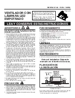
RECESSED
LED FAN / LIGHT
READ AND SAVE THESE INSTRUCTIONS
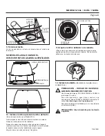
To clean trim ring / baffle:
Vacuum with a soft brush attachment
or remove trim ring / baffle and clean with a soft cloth and mild
soap or detergent. Dry thoroughly before reinstalling.
To clean inside of housing:
Remove trim ring / baffle and
vacuum inside of housing with a soft brush attachment.
OPERATION
The fan and light can be operated using various combinations of
on/off switches and controls:
• Fan and light controlled with single on/off switch
• Fan and light controlled with separate on/off switches
• Fan controlled with timer control
• Selectable fan CFM - 50 or 80
See “Connect Wiring” section for various wiring options.
CLEANING
MAINTENANCE
Motor is permanently lubricated. Do not oil or disassemble motor.
For Warranty Statement, Service Parts, Technical
Support, or to Register your product, please visit our
website or call:
In the United States - Broan.com 800-637-1453 or
NuTone.com 888-336-6151. In Canada - Broan.ca or
NuTone.ca 877-896-1119
Installer: Leave this manual with
the homeowner.
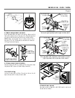
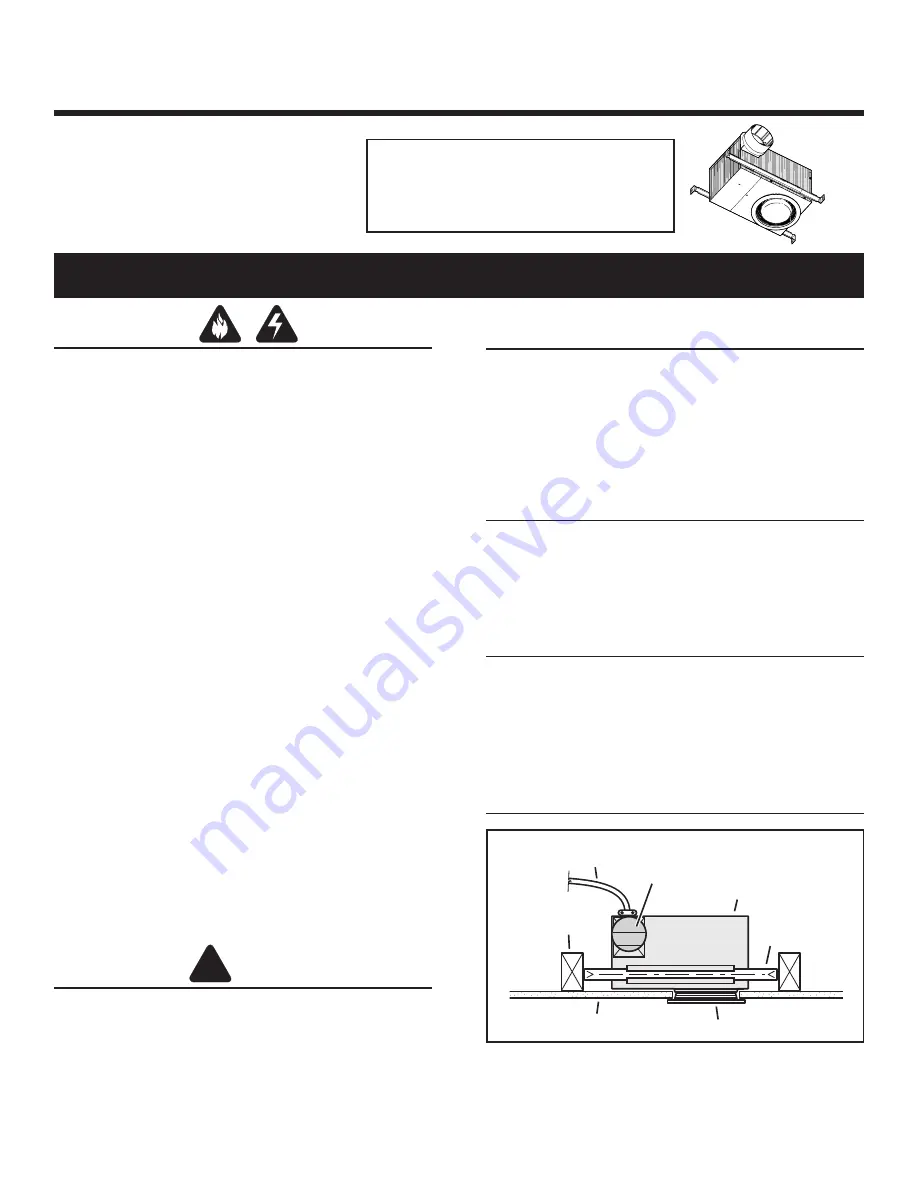
HOUSING
MOUNTING
BRACKET
CEILING
JOIST
POWER
CABLE
TRIM RING / BAFFLE
FINISHED CEILING
4" ROUND
DAMPER/DUCT
CONNECTOR &
4” ROUND
DUCTWORK
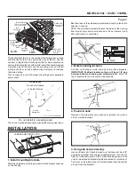
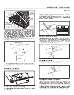
PLAN THE INSTALLATION
The unit can be installed anywhere between ceiling joists using
mounting brackets provided.
*
Install in a flat ceiling only.
Typical Installation
*