Brocade Communications Systems FastIron SX 1600, Hardware Installation Manual
The Brocade Communications Systems FastIron SX 1600 is a highly advanced networking device that delivers exceptional performance and reliability. With its comprehensive Brochure & Specs manual, available for free download on our website, users can gain in-depth knowledge about the product's features and specifications to optimize its usage.
Share
Download


Reviews:
No comments
Related manuals for FastIron SX 1600

CH3130
Brand: H&S Pages: 32

FlexPoint LMC200A-2PS-DC
Brand: Black Box Pages: 4

VSN1100X
Brand: Datapath Pages: 20

PXI-1036DC
Brand: National Instruments Pages: 62

474 Series
Brand: Ihse Pages: 89

SC825S2-560LPV
Brand: Supermicro Pages: 72

Z-421V
Brand: Panasonic Pages: 47
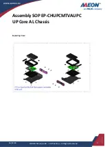
Aaeon UP Core AL
Brand: Asus Pages: 11

LCP22
Brand: Comet Models Pages: 2

F1C
Brand: Streacom Pages: 8

BC1
Brand: Streacom Pages: 10


