background image


V. 1.3-24-04-19 

brookvent.co.uk 


VERSATILE 

Heat Recovery Ventilation 


Installation, maintenance & user manual 

 
Applicable to the following aircycle 1.3 & 1.3+ models: 


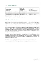
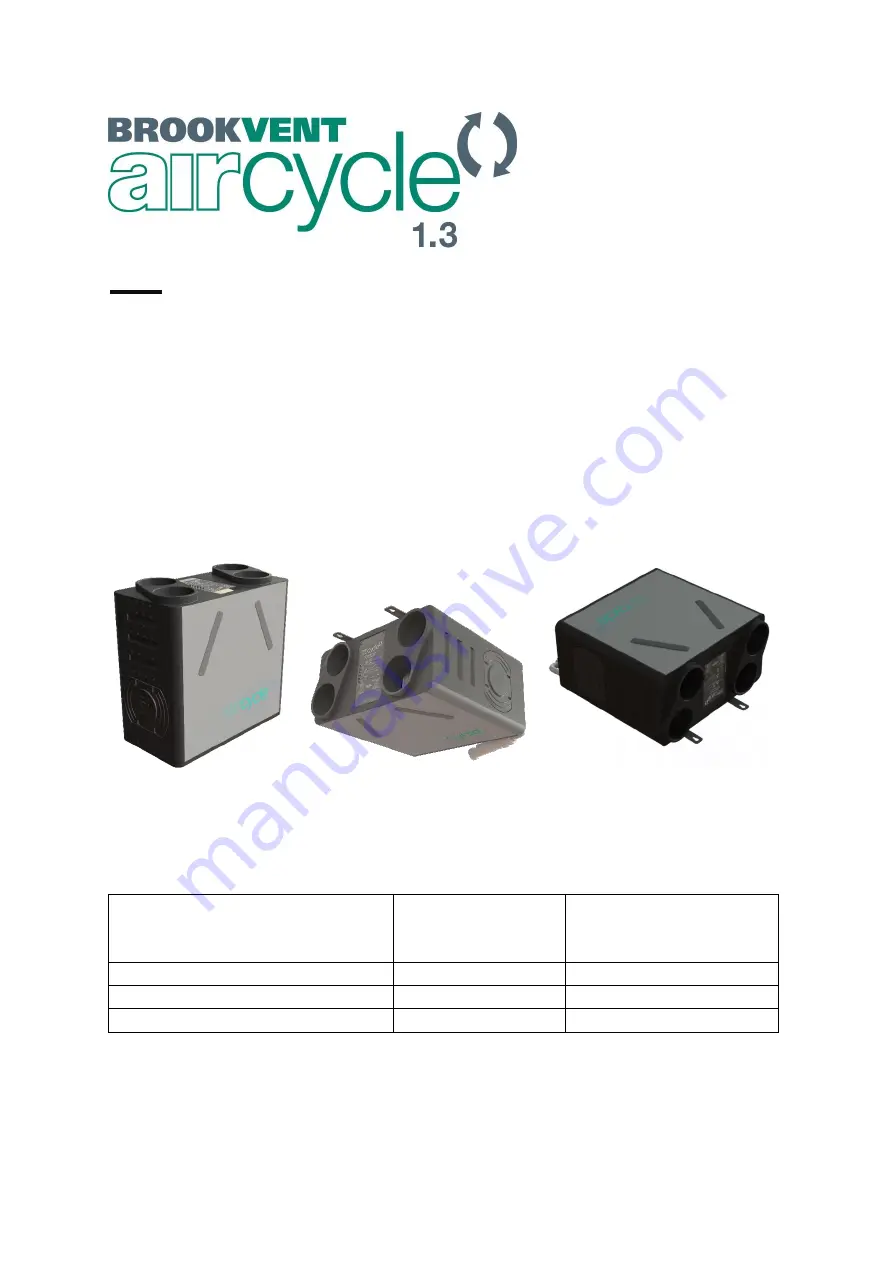
aircycle MVHR  
Product Type 

aircycle 1.3  
Potentiometer Control 

aircycle 1.3+ 
Potentiometer Control 

c/w Humidistat, Bypass - Wall Mount 

AS 90-0103-WINS-01 

AS 90-0103P-WINS-01 

c/w Humidistat, Bypass - Floor Mount 

AS 90-0103-FINS-01 

AS 90-0103P-FINS-01 

c/w Humidistat, Bypass - Ceiling Mount 

AS 90-0103-CINS-01 

AS 90-0103P-CINS-01 


Product codes shown refer to "Standard" duct configuration. 
Add "V" to the end of each product code for an "inverted duct configuration.  

AND HIGHLY 


QUIET, EFFICIENT


Summary of Contents for aircycle 1.3

Page 1: ...ol aircycle 1 3 Potentiometer Control c w Humidistat Bypass Wall Mount AS 90 0103 WINS 01 AS 90 0103P WINS 01 c w Humidistat Bypass Floor Mount AS 90 0103 FINS 01 AS 90 0103P FINS 01 c w Humidistat By...

Page 2: ...CTIONS WITH THE PRODUCT Please read this manual fully prior to installing the MVHR unit 1 0 Introduction 2 2 0 Safety 4 3 0 Specifications Dimensions mm 6 4 0 Installation 11 5 0 Electrical Connection...

Page 3: ...nts with restricted space The system should be run continuously 24 hours a day and should only be disconnected by a competent person during service or maintenance Heat Recovery ventilation works best...

Page 4: ...parts and labour and the remaining 4 years covering parts only In the instance of a defect Brookvent may repair the product replace the product free of charge or refund the cost of the product at Broo...

Page 5: ...e external surface do so with a dry cloth only 2 2 Responsibility of the Installer Correct Installation balancing and commissioning of the MHRV unit Record measured air flow volumes on each of the val...

Page 6: ...issues It is important that the filters are changed at least once per year or as required In new build properties it may be prudent to check change your filters after the first 3 months of occupancy...

Page 7: ...6 V 1 3 24 04 19 brookvent co uk www brookvent co uk T 44 0 28 9061 6505 3 0 Specifications Dimensions 3 01 WALL MOUNT 3 02 CEILING MOUNT...

Page 8: ...7 V 1 3 24 04 19 brookvent co uk www brookvent co uk T 44 0 28 9061 6505 3 03 FLOOR MOUNT 3 1 Duct Connections...

Page 9: ...r media G3 Filter cover Rubber Mounting Bracket Zinc Plated Steel Fan Scrolls ABS Electrical Controls 230v EC Low energy backward curved centrifugal fans Supplied complete with 4 core flying lead Live...

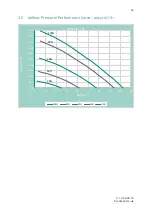
Page 10: ...05 3 3 SAP Appendix Q Results 3 4 Airflow Pressure Performance Curve aircycle 1 3 0 0 50 0 100 0 150 0 200 0 250 0 300 0 350 0 400 0 450 0 500 0 550 0 600 0 0 0 10 0 20 0 30 0 40 0 50 0 60 0 70 0 80 0...

Page 11: ...vent co uk T 44 0 28 9061 6505 3 5 Airflow Pressure Performance Curve aircycle 1 3 0 0 50 0 100 0 150 0 200 0 250 0 300 0 350 0 400 0 450 0 500 0 0 10 20 30 40 50 60 70 80 90 Pressure Pa Airflow l s A...

Page 12: ...lified electrician The MVHR unit is designed to be installed indoors within an attic storage cupboard or void space away from exposure to frost water or intense heat The system should be installed in...

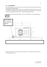
Page 13: ...the mounting surface can safely bear the load of the unit using suitable screw fixings One bracket will be secured to the back of the unit as shown in Fig 1 the second bracket should be secured to the...

Page 14: ...xings provided The brackets can only be fitted to the unit in one way the fixing holes are colour coded to help with fixing orientation When the brackets have been fitted ensure that they are in the c...

Page 15: ...ling Mounting Bracket Quantity 2 No 5 M8 Anti Vibration Washer Quantity 8 No 3 M8 x 30 Celling Anchor Quantity 4 No 6 M8 x 16 Socket Cap Bolt Quantity 8 No 4 M8 x 24 Washer Quantity 4 Please ensure th...

Page 16: ...ay the fixing holes are colour coded to help with fixing orientation When the brackets have been fitted ensure that they are in the correct position as shown in Fig 1 Before mounting to the floor The...

Page 17: ...ble Where it is not possible to continue throughout the dwelling in rigid 125mm diameter round pipe due to the void spaces available a conversion to rigid 204mm x 60mm flat rectangular ducting is reco...

Page 18: ...systems as shown above to prevent the back flow of air into the HRV unit from the waste discharge system It is imperative that there is a gravitational fall from the unit to the discharge point ensuri...

Page 19: ...r into the HRV unit from the waste discharge system It is imperative that there is a gravitational fall from the unit to the discharge point ensuring that the water drains from the unit A minimum fall...

Page 20: ...into the HRV unit from the waste discharge system It is imperative that there is a gravitational fall from the unit to the discharge point ensuring that the water drains from the unit A minimum fall o...

Page 21: ...ator as to comply with current IEE wiring regulations A switch or circuit breaker must be used in the power supply circuit It should be in close proximity to the HRV unit and should be clearly marked...

Page 22: ...f the trickle and boost rates for the supply and extract fans within the unit These separate speed options allow one speed to be set for normal day to day operation I e Trickle and an increased speed...

Page 23: ...ract Trickle Extract Boost Supply Trickle Supply Boost Front Humidity 60 100 Boost Over run 0 15mins NB On standard configuration systems the controls are located on the RHS as shown Inverted configur...

Page 24: ...ply trickle rate DO NOT ADJUST THE VALVES 8 Turn the Boost Switch on or trigger the boost by other means provided e g bathroom light switch relay if applicable 9 Turn the Supply Boost up until the tot...

Page 25: ...es down Turn the boost switch on Turn the Extract boost spindle up until the extract boost rates are achieved kitchen 13l s bathroom 8l s En suite 8 l s Lock the valves in place Turn the boost switch...

Page 26: ...is used to boost the system When a live 230v signal is applied by a switch or sensor the boost function will be triggered When the signal stops the boost will over run for a minimum of 15 mins as to...

Page 27: ...of air directed around the Heat Recovery Core as the temperature of the supply air from outside rises thus comfortably regulating the indoor air temperature during warmer months This feature is factor...

Page 28: ...s and humidistats These connecting circuits may be used to trigger the auto boost the system It is important to follow all guidelines relating to the maintenance of this HRV system to ensure the unit...

Page 29: ...s after the first 3 months of occupancy depending on the amount of residual building dust present within the property 7 2 Heat Exchange Core Check only select models The aircycle 1 3 heat recovery cor...

Page 30: ...g the plastic strip running across the front of the heat exchanger Step 5 Carefully remove any dust from the heat exchanger with a household vacuum cleaner Do not attempt the clean the heat exchanger...

Page 31: ...Step 4 Remove the brackets and the back panel Step 5 Remove the foam panels and then the heat exchanger from the unit by plastic strip running in front of the heat exchanger Step 6 Carefully remove an...

Page 32: ...mount Step 5 Turn the fan mount anti clockwise to the line marked on the fan case and then pull straight out Step 6 Place the new fan assembly in the fan case lining it up with the line marked in the...

Page 33: ...the heat exchanger Step 5 Plug the new sensor in place and screw it to the case care should be taken when handling the new sensor to avoid Electro static discharge damaging the sensor ensure you are...

Page 34: ...aken when handling the new sensor to avoid Electro static discharge damaging the sensor ensure you are earthed when handling Step 6 Carefully reinsert the heat exchange core into the unit and replace...

Page 35: ...of foot A shown against the yellow stand off in the enclosure Step 6 This will ensure that the spindles line up with the holes in the enclosure lid Step 7 For inverted units white label line foot A u...

Page 36: ...loose over time and are kept sufficiently tight 8 0 User Operation The Brookvent aircycle 1 3 is an extremely compact and highly efficient Mechanical Heat Recovery Ventilation HRV MHRV system specifi...

Page 37: ...tic control options if any Passive Infra red PIR Sensors These are motion sensing switches these sensors trigger the system into boost mode when activity motion is detected in a particular room They a...

Page 38: ...oms and or kitchens When pressed it will trigger the system into boost mode for a defined time Trickle and Boost switch This is a simple on off switch with no determined time delay When the switch is...

Page 39: ...models only See section 6 7 of this manual The system is constantly in Boost New houses can be quite damp with items drying out this can cause the inbuilt humidistat and external humidistats to activa...

Page 40: ...39 V 1 3 24 04 19 brookvent co uk www brookvent co uk T 44 0 28 9061 6505 Notes...

Page 41: ...40 V 1 3 24 04 19 brookvent co uk www brookvent co uk T 44 0 28 9061 6505 Notes...

Page 42: ...query you may have and we will be more than happy to assist you Brookvent Brook House Dunmurry Industrial Estate Dunmurry Belfast Northern Ireland BT17 9HU T 44 0 28 9061 6505 It is important to retai...

Reviews: