background image

DH4-B980

RH-9800

Please read this manual before using the machine.
Please keep this manual within easy reach for quick reference.

ELECTRONIC EYELET BUTTON HOLER

INSTRUCTION MANUAL

Summary of Contents for DH4-B980

Page 1: ...DH4 B980 RH 9800 Please read this manual before using the machine Please keep this manual within easy reach for quick reference ELECTRONIC EYELET BUTTON HOLER INSTRUCTION MANUAL ...

Page 2: ...afe operation of this machine and to prevent accidents and injury to yourself or other people The meanings of these indications and symbols are given below Indications DANGER The instructions which follow this term indicate situations where failure to follow the instructions will almost certainly result in death or severe injury CAUTION The instructions which follow this term indicate situations w...

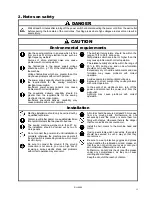
Page 3: ...h correct operation Avoid exposure to direct sunlight during use Exposure to direct sunlight may cause problems with correct operation In the event of an electrical storm turn off the power and disconnect the power cord from the wall outlet Lightning may cause problems with correct operation Installation Machine installation should only be carried out by a qualified technician Contact your Brother...

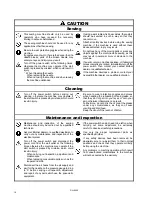
Page 4: ...tart switch is pressed by mistake which could result in injury Be sure to wear protective goggles and gloves when handling the lubricating oil and grease so that they do not get into your eyes or onto your skin otherwise inflammation can result Furthermore do not drink the oil or eat the grease under any circumstances as they can cause vomiting and diarrhoea Keep the oil out of the reach of childr...

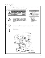
Page 5: ...r guard Needle bar guard Belt cover etc 3 Do not touch the knife or press any objects against the machine while sewing as this may result in personal injury or damage to the machine 4 Be sure to connect the ground If the ground connection is not secure you run a high risk of receiving a serious electric shock and problems with correct operation may also occur 5 Direction of operation Belt cover Ne...

Page 6: ...emory switch 27 6 7 List of error codes 29 7 SEWING 30 7 1 Using the EMERGENCY STOP switch 30 7 2 Sewing 31 7 3 Adjusting the thread tension 32 7 4 Needle and knife position 33 7 5 Using the production counter 35 7 6 Using a cycle program 36 7 7 Setting the feed bracket to the front position 37 7 8 Switching between single pedal and dual pedal operation Switching the foot controller 37 7 9 Using f...

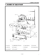
Page 7: ... NAMES OF EACH PART 1 Front cover 2 EMERGENCY STOP switch 3 Upper shaft pulley 4 Control panel 5 Control box 6 Front panel 7 Start switch 8 Cloth presser switch 9 Foot controller 10 Power switch 11 Motor 8 10 9 1 2 4 7 3 5 1096Q 11 6 ...

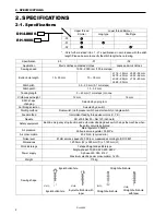
Page 8: ... pulse motors X Y θ Needle DO x 558 Nm 80 Nm 120 Schmetz Safety equipment Built in emergency stop function and automatic stopping device which stops the machine when the safety circuit is activated Air pressure Main regulator 0 5 MPa Knife pressure regulator 0 3 MPa Air consumption 43 2 l min 8 cycles min Noise level 81 dB at max speed of 2 000 rpm measured according to ISO 10821 Dimensions 1 200 ...

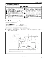
Page 9: ...not excessively bend the cords or secure them too firmly staples otherwise there is the danger that fire or electric shocks could occur Be sure to connect the ground If the ground connection is not secure you run a high risk of receiving a serious electric shock and problems with correct operation may also occur Install the belt covers to the machine head and motor 3 1 Table processing diagram Use...

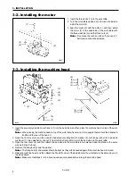
Page 10: ...there to hold the handles A and B and the rear of the head C 2 Open the front cover 2 and then use the bed stand mounting bolt 3 washer 4 cushioning rubber 5 bed stand cushion A 1 large washer 6 and nut 7 to attach the front right corner of the bed stand to the work table 3 Open the rear cover 8 and then attach the bed stand to the work table in two places inside the stand in the same way as in st...

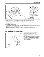
Page 11: ...rd you gently remove the head support lever 2 from the hinge lever support shaft 3 and then gently lower the machine head Note Do not hold the machine head by the feed bracket 4 or X feed shaft A 5 when it is being raised and lowered 3 4 Installing the oil container 1 Install the oil draining cap support 2 to the base of the bed stand 1 with the two screws 3 2 Screw the oil container 4 into the oi...

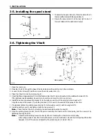
Page 12: ...sting prevention bracket 8 to the pulley cover 3 with the wing bolt 6 and washer 7 Align the center of the washer 7 with the gradation 7 0 shown on the outside of the pulley at this time 7 Provisionally tighten the winding prevention bar 9 to the pulley cover 3 with the wing bolt 10 8 Install the pulley cover 3 and tighten it with the two screws 2 Note Check that the V belt is not touching the bel...

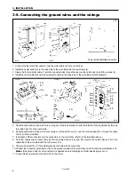
Page 13: ...the installation position 1 Install the air unit 1 to the underside of the work table with the two screws 2 2 Install the valve assembly 3 with the two screws 4 3 Connect air hose No 15 to the intermediate joint 5 of the air unit 1 and to the joint 6 of the valve assembly 3 and connect air hose No 16 to joints 7 and 8 Connecting the knife valve cables Connect the two black knife valve cables to te...

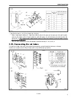
Page 14: ...he machine head 12 through the cable hole 13 in the work table 7 Insert each of the connectors into the connectors on the control box Refer to the illustration above 8 Pass the cables and air hoses through the two cable holders 14 and then secure the cable holders 14 to the underside of the work table with the two screws 15 9 The ground wires 16 17 should always be connected to the control box 10 ...

Page 15: ...ir tubes Connect the air tubes to the joints of the solenoid valve assembly using the illustration below as a reference Numbers are marked on each of the air hoses which come out of the sewing machine Specification Label No of harness Right left cloth presser No Right left movable knife No Thread handler No L1 1 1 L2 2 2 L3 3 3 L4 4 4 L5 5 5 L6 6 6 L7 7 7 02 No 10 Label No 1 1112Q 1113Q No No 5 2 ...

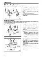
Page 16: ...essure will increase when the knob 2 is turned clockwise 2 Gently lift the knob 4 of the knife pressure adjustment regulator 3 and turn it in the direction of the arrow in the illustration The pressure will increase when the knob 4 is turned clockwise The pressure for the knife pressure adjustment regulator 3 is adjusted to 0 3 MPa Be careful not to increase this pressure needlessly otherwise poor...

Page 17: ...ion may also occur Do not connect the power cord until installation is complete otherwise the machine may operate if the start switch is pressed by mistake which could result in injury 1 Attach an appropriate plug to the power cord 1 The green and yellow wire is the ground wire 2 Insert the plug into properly grounded AC power supply Note Do not use extension cords otherwise machine operation prob...

Page 18: ...sight glass If the oil level is low replenish the oil supply Filling the arm oil tank Filling the bed base oil tank 4 2 Lubrication Oil these parts once a day Oil the moving parts of the needle bar looper and spreader mechanisms and also the cam groove roller the felt at the base of the wick and the wick before using the sewing machine for the first time and also after long periods of non use When...

Page 19: ...t its touching the needle Raise cloth presser plate U 9 pass the needle through the hole and then remove cloth presser plate U 9 from the pin 8 5 Remove the left cloth presser plate 10 in the same way as the right cloth presser plate 5 was removed 6 Open the front cover 7 Turn the race stand and add a few drops of oil to the spreader cam 11 and to the supports for the looper link 12 and spreader l...

Page 20: ...n the power back on again Note A buzzer will sound while the data is being initialized 6 Turn off the power 7 Set DIP switch No 1 3 on the circuit board to OFF 8 Close the rear plate 2 and tighten the five screws 1 5 2 Changing the lower thread and gimp trimming The sewing machine is set to lower thread and gimp trimming when it is shipped from the factory DIP switch No 6 3 is set to ON Carry out ...

Page 21: ... setting position 4 Press the MODE button 6 to switch to automatic mode The AUTO mode indicator will illuminate 5 Depress the cloth presser switch 7 The cloth presser 8 will be lowered 6 Depress the start switch 9 The machine will sew one buttonhole and will then stop If the buzzer makes a beeping sound and E 89 appears on the front panel display the direction of operation of the upper shaft is re...

Page 22: ...crew 2 5 Remove the cloth presser plates Refer to page 13 Note After removing the cloth presser plates check that the index mark 4 on the machine head is aligned with the index mark 5 on the race stand before inserting the needle 3 when the race stand is turned fully to the right 6 Lower the finger guard 1 5 5 Threading the upper thread CAUTION Turn off the power switch before threading the thread...

Page 23: ...d Remove the cloth presser plates refer to page 13 and then thread the lower thread as shown in the illustration below For upper thread trimming specifications 00 For upper and lower thread trimming specifications 01 02 0879Q 0881Q 0880Q 0883Q 0882Q 0881Q ...

Page 24: ...terial 1 Insert the material so that it touches the right and left cloth guides 1 2 The sewing margin can be adjusted to within 10 30 mm 3 Loosen the screws 2 at left and right and move the cloth guides 1 back and forth to adjust the sewing margin 00 01 02 0884Q 0885Q 0886Q Pass the gimp through the hole of the thread tension stud 1 Refer to 9 17 Adjusting the gimp length after trimming 02 Page 54...

Page 25: ...CYCLE PROGRAM indicator PROGRAM NUMBER button AUTO mode Indicator FEED mode indicator MANUAL mode indicator PROGRAM mode indicator MODE button KNIFE button AFTER indicator OFF indicator BEFORE indicator B EYELET PATTERN indicator C LENGTH indicator D TACKING LENGTH indicator E OFFSET indicator F STITCH PITCH indicator M SELECT button K Down button I KNIFE POSITION indicator J Front panel display L...

Page 26: ...bers are displayed in the program number display window 2 in the following order each time the button is pressed 1 2 9 C 6 3 Changing the mode 1 Press the MODE button 1 The mode changes in the following order each time the button is pressed AUTO FEED MANUAL PROGRAM Automatic mode is used for normal sewing Feed mode is used to move the feed bracket with out sewing in order to check component positi...

Page 27: ...ogram number display window 3 4 Press the SELECT button M to select a letter from A to P4 The character displayed changes in the following order each time the button is pressed A B P4 Then make the required settings by following steps 5 and 6 below 5 Press the Up button L or the Down button K to change the setting value When the setting value is changed the numerals appearing in the display will f...

Page 28: ... length of between 10 and 38 mm 10 to 50 mm with no looper thread trimmer in steps of 1 mm Note You cannot set the buttonhole length to a value that would make the difference between the buttonhole length and the tacking length less than 7 mm 2 Press the Up button L or the Down button K to set the desired buttonhole length When the setting value is being changed the numerals appearing in the displ...

Page 29: ...d normally be set to half the stitch width If a tacking length that is outside the 0 3 mm range is set it will be set back to 1 5 mm automatically 2 Press the Up button L or the Down button K to set the desired offset When the setting value is being changed the numerals appearing in the display will flash 3 Press the ENTER button N to accept the new offset setting The display will stop flashing Ex...

Page 30: ...utting space When the setting value is being changed the numerals appearing in the display will flash 3 Press the ENTER button N to accept the new cutting space setting The display will stop flashing I Setting the knife position compensation 1 The knife position compensation can be set to between 0 7 and 0 7 mm in steps of 0 1 mm If you would like to move the knife closer to the seam set to a nega...

Page 31: ...seen from the finished side or the reverse side when sewing 2 Press the up button L or the down button K to set the Y correction value When the setting value is changed the value displayed will start to flash 3 Press the ENTER button N to accept the Y correction setting The display will stop flashing and will start illuminating steadily P3 Setting θ1 correction 1 The setting range is from 3 to 3 i...

Page 32: ...e eyelet seam clockwise when seen from the finished side or the reverse side when sewing 2 Press the up button L or the down button K to set θ2 correction value When the setting value is changed the value displayed will start to flash 3 Press the ENTER button N to accept the θ2 correction setting The display will stop flashing and will start illuminating steadily 1158Q 1159Q L N K ...

Page 33: ... normal standby mode No Contents Setting range Initial value 00 Bar tacking at the sewing start to prevent fraying OFF Disabled ON Enabled OFF 01 Number of stitches for memory switch No 00 Does not appear when memory switch No 00 is set to OFF 01 1 stitch 02 2 stitches 03 3 stitches 01 02 Bar tacking at the sewing end to prevent fraying OFF Disabled ON Enabled OFF 03 Number of stitches for memory ...

Page 34: ... cutting block Timer for determining if cutting block is lowered OFF Disabled Determined from slit signal stopping ON Enabled Determined by timer OFF 17 Time for memory switch No 16 Does not appear when memory switch No 16 is set to OFF 42 420 ms 45 450ms 48 480ms 51 510ms 54 540 ms 45 18 Changing cutting block ON time Disabled always OFF when memory switch No 16 is ON OFF Disabled 25 ms ON Enable...

Page 35: ...ss the RESET button E 40 Needle bar has not been raised Raise the needle to the needle up position and then press the RESET button E 42 Cutting block is lowered Turn off the power E 45 Lower thread and gimp trimming knife does not retract Turn off the power E 46 Upper thread trimming knife does not retract Turn off the power E 50 X axis is not at the home position Turn off the power E 51 Y axis is...

Page 36: ...is time by pressing the up button L and Down button K 3 To continue sewing press the start switch 3 The TROUBLE indicator will switch off the E 60 will be cleared from the front panel display and sewing will begin again To stop sewing press the RESET button 4 The TROUBLE indicator will switch off the E 60 will be cleared from the front panel display and the feed bracket will return to the cloth se...

Page 37: ...ront panel display J at this time turn the pulley to set the needle to its upper position and press the RESET button 3 3 Press the PROGRAM NUMBER button 4 to select the desired program number Refer to page 20 4 Press the MODE button 5 to switch to automatic mode The AUTO indicator 6 will illuminate 5 Press the KNIFE button 7 to select cutting before sewing OFF no cutting or cutting after sewing Re...

Page 38: ... the lower thread tension is when the lower thread is pulled out from the needle hole in the throat plate Upper thread tension Lower thread tension Adjusting the lower thread take up spring tension and stroke Tension adjustment Loosen the screw 3 and turn the thread take up spring support 4 in the direction indicated by the arrow to increase the tension of the spring 5 Stroke adjustment Loosen the...

Page 39: ...g 1 2 1 X 3 2 1 9 X 2 8 2 4 X 3 9 2 2 8 X 4 3 2 4 X 3 9 3 3 X 4 6 3 3 0 X 4 6 3 2 X 4 1 3 6 X 4 8 4 3 2 X 5 4 2 8 X 4 7 3 6 X 6 1 5 Straight Straight Straight 6 3 8 X 4 3 3 2 X 3 6 4 0 X 4 5 3 At the time of shipment the installation position for the knife is adjusted to the position shown in the illustration at left when the cutting space H and the knife position compensation value I are 0 Explan...

Page 40: ...ting before sewing the difference between a and a will change depending on the cloth opening amount 2 Set the knife position compensation value I so that the two are equal Move the knife to the positive direction when increasing the cloth opening amount Refer to I Setting the knife position compensation on page 24 1166Q a a 1167Q Knife position compensation a a a a a a a a ...

Page 41: ...he MODE button 1 to switch to automatic mode 2 Press the ENTER button N The units digit will start flashing in the display 3 Press the Up button L or the Down button K to set the value for the units column and then press the ENTER button N Repeat this step for the tens hundreds and thousands columns The production counter function can be stopped by setting counter to 0000 When the thousands column...

Page 42: ...N The dot in the thousands column will illuminate steadily and the number in the hundreds column will start flashing When the dot is illuminated the knife will operate and when the dot is switched off the knife will not operate However if the OFF indicator illuminates during sewing the knife will not operate even if the dot is illuminated 6 Repeat steps 3 to 5 for the hundreds and tens columns 7 P...

Page 43: ... normal Refer to page 30 7 8 Switching between single pedal and dual pedal operation Switching the foot controller The cloth presser can be lowered and the machine can start sewing just by pressing the start switch without having to use the cloth presser switch 1 Turn off the power 2 Change the setting of DIP switch No 5 OFF To use both pedals cloth presser switch and start switch ON To use only o...

Page 44: ...tch 2 The cloth pressers will be lowered 3 Press the start switch 3 The feed bracket 4 will move to the sewing start position When the start switch 3 or the Up button L is pressed the feed bracket 4 will move to the next sewing position If the Down button K is pressed the feed bracket 4 will move to the previous sewing position To return the feed bracket 4 to the cloth setting position while sewin...

Page 45: ... The feed bracket 4 will move to the next sewing position in accordance with the rotation of the upper shaft Note If the upper shaft pulley 5 is turned in the wrong derection the feed bracket timing may become disrupted To return the feed bracket 4 to the cloth setting position while sewing 1 Press the EMERGENCY STOP switch 6 2 Press the RESET button 7 The feed bracket 4 will then return to the cl...

Page 46: ...the desired setting If you would like to switch the display from the cycle program to the production counter press the SELECT button M The production counter will be displayed while this switch is being pressed 7 12 Setting the number of home position cycles The number of home position cycles can be set in order to shorten the overall cycle time This function is only valid when DIP switch No 8 on ...

Page 47: ...is setting will apply to all program numbers from 1 to 9 The display will stop flashing and will start illuminating steadily Note If for some reason an excessive load is applied to the feed bracket which causes it to slip then there is the danger that this will have an adverse effect on subsequent sewing operations Therefore it is recommended that you return to the home position for each cycle i e...

Page 48: ...belt resulting in operating problems 1 Turn off the power 2 Turn the air cock to stop the air Turn the knob to release the air 3 Remove any thread scraps and dust etc from the thread paths for the needle thread looper thread and gimp In particular the looper thread path should be cleaned every day to keep it free from thread scraps and dust 4 Check the oil level by looking at the sight glass If th...

Page 49: ...to re install them to their original positions and check that they operate correctly before using the machine 9 1 Adjusting the height of the spreader and looper Spreader height The clearance between the left spreader forked spreader and the left looper must be set to match the thickness of the lower thread The clearance between the right spreader and the right looper should be as small as possibl...

Page 50: ...se the calipers to take the same measurement as taken in step 2 Find the difference between the measurements taken in this step and in step 2 4 Follow the same procedure as in step 3 above to find the difference between the two measurements when the needle 3 is at the outside sewing position When the needle 3 is at the inside sewing position the tip of the left looper 4 should be aligned with the ...

Page 51: ... top of needle bar bracket 2 and then turn the upper shaft pulley until the end of the needle bar 1 touches the edge of the calipers B Check that the tip of the left looper is aligned with the center of the needle at this time 4 In the same way check that the tip of the right looper is aligned with the center of the needle when the needle is at the outside sewing position 5 If the tips of the loop...

Page 52: ... bar clamp 5 and the needle bar horizontal link 6 can maintain their oil films This will help to ensure that the needle bar turns smoothly 9 5 Adjusting the clearance between the looper and needle Be sure to carry out this adjustment after changing the size of the needle The clearance between the tip of the looper and the needle should be 0 05 0 2 mm 1 Loosen the looper screw 1 and then adjust the...

Page 53: ... that the looper clasps the upper thread securely 9 7 Adjusting the spreader mounting positions 1 Loosen the screw 3 and adjust the position of the left spreader stopper 4 so that the fork of the left spreader 1 is aligned with the lower thread guide hole of the left looper 2 2 Loosen the screw 7 and adjust the position of the right spreader stopper 8 so that the tip of the right spreader 5 is ali...

Page 54: ...ew 3 to adjust the spreader timing 3 After adjusting tighten the nut 2 and the screw 1 9 9 Adjusting the needle racking width stitch width The needle racking width is set to 3 mm at the time of shipment from the factory 1 Loosen the needle racking adjustment nut 1 and then adjust the needle racking width by sliding the adjustment screw 2 vertically along the oval slot The stitch width becomes smal...

Page 55: ...e cutting block grind the cutting block as shown in A in the above illustration Cutting block length A Knife cutting length 1 5 mm 3 When installing the cutting block push in the pin 3 and then tighten the screw 1 Do not use knives with different numbers on the same cutting block If knives with different numbers are used accurate cutting will not be possible and the knife will be damaged Changing ...

Page 56: ...d cutting block after the knife has been replaced otherwise it may damage the tip of the knife Adjusting the contact between the knife and the cutting block To see the knife incision more easily color the cutting surface of the cutting block with a marker pen 1 Operate the cutting block three times with the knife making a mark on it each time 2 Adjust the position of the cutting block or contact b...

Page 57: ... the knife and cutting block as a set If knives with different numbers are used on the same cutting block accurate cutting will not be possible and damage to the knife may result 9 13 Adjusting the cutting pressure Adjust the cutting pressure to the minimum pressure that still allows the material to be cut If the knife cutting length is 20 mm sufficient cutting performance can be obtained with an ...

Page 58: ...he left and right cloth presser plates are equal It is usually sufficient for one cloth presser plate to open by 0 8 mm Measuring the opening amount 1 Switch the mode to feed mode Refer to page 20 2 Lower the cloth presser and then use calipers to measure the distance a 3 Press the start switch The feed bracket will move and then the left and right cloth presser plates will open 4 Use calipers to ...

Page 59: ...kipped stitches may result 9 16 Adjusting the trimming of the lower thread and gimp 00 01 The lower thread and gimp should be trimmed at the correct time after the feed bracket has returned to the home position Thread trimming operation can be checked in steps while manual mode is active Refer to Using manual mode on page 39 1 The mechanism is adjusted so that the lower thread and gimp are separat...

Page 60: ...that the lower thread and gimp are spread by the thread handler 1 2 The movable knife driving cam 2 operates and the right movable knife 3 and left movable knife 4 mesh and the thread is cut 9 17 Adjusting the gimp length after trimming 02 Adjust so that approximately 4 mm of the gimp thread is coming out from the throat plate 1 1 Loosen the screw 2 and move the gimp thread guide J 3 in the direct...

Page 61: ...e end of the lower thread is securely held between the lower thread presser 1 and the throat plate 2 9 19 Sub presser 02 Trimming of the lower thread and gimp is carried out when the cloth pressers rise The sub presser 1 endures that the material does not move during thread trimming in order to maintain a stable thread length after trimming 2 1 0986Q 1 0987Q ...

Page 62: ...N Front position 3 OFF Back position ON Counting down to zero 4 OFF Counting up from zero ON Pedal 1 operation 5 OFF Pedal 2 operation ON Compatible with normally closed type emergency stop switch new 6 3 OFF Compatible with normally open type emergency stop switch old ON Upper thread remaining amount Large 7 2 OFF Upper thread remaining amount Standard ON Spare 8 OFF Spare 1 The version of the PR...

Page 63: ... OFF Description ON Data initialization 1 OFF Normal ON Input check 2 OFF Normal ON Output check 3 OFF Normal ON Upper gimp guide present 4 1 OFF Upper gimp guide not present ON Upper thread nipper present 5 2 OFF Upper thread nipper not present ON Upper and lower thread trimming 6 OFF Upper thread trimming ON Material is remains pressed after sewing 7 OFF Material is released after sewing ON Need...

Page 64: ...16 Needle and looper adjustment is incorrect Adjust the needle bar height or the looper and spreader height 43 Thread breaks Needle looper throat plate or thread path is damaged Repair the damage with an oilstone or buffer or replace the damaged part Thread tension control nut pressure is too strong or too weak Adjust to an appropriate pressure 32 Needle point is broken or bent Replace with a new ...

Page 65: ...e air pressure 51 Lower thread is not cut Movable knife position is incorrect Adjust the position of the movable knife or the loop spreader 53 Thread nipper spring force is too weak Adjust the force of the thread nipper spring 53 Upper thread length is too short after trimming Install the upper thread trimmer knife so that it cuts only one side of the upper thread loop 53 Needle and looper adjustm...

Page 66: ...INSTRUCTION MANUAL 15 1 Naeshiro cho Mizuho ku Nagoya 467 8561 Japan Phone 81 52 824 2177 Printed in Japan BROTHER INDUSTRIES LTD 118 980 S91980 302 2001 11 H 1 ...

Reviews: