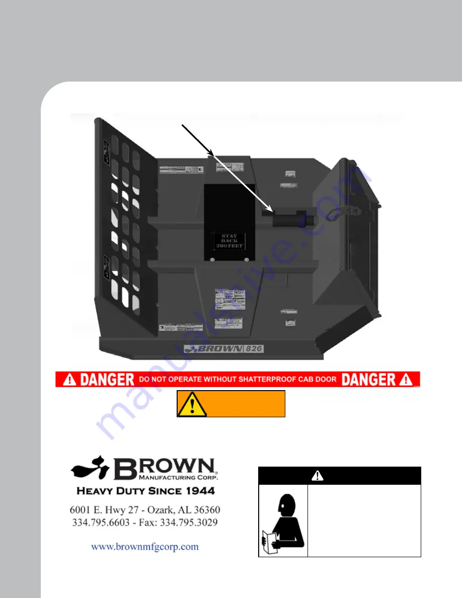
background image

Owner / Operator Manual

Brown 815 

Brush Cutter

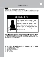
Before operating your machine, 

stop and read this owners manual.  

Do not attempt to operate the unit 

until you fully understand the 

material covered in this manual.  

Without the knowledge contained 

in this manual, injury or death can 

result.

WARNING

For use with models having serial numbers with “

A

” as 

the 

FOURTH

 digit:

Example:  815A0001

Lift Restriction Chains

 must be attached from the skid loader to the brush cutter to keep the 

cutter below the level of the operator BEFORE operating this machine. See 

Page 17

 for further 

information.

ATTENTION:

ALL WARRANTY WORK 

MUST

 BE APPROVED 

BY BROWN MFG. CORP. 

BEFORE

 WORK BEGINS

Serial Plate Location

WARNING

Summary of Contents for 815

Page 1: ...this manual injury or death can result WARNING For use with models having serial numbers with A as the FOURTH digit Example 815A0001 Lift Restriction Chains must be attached from the skid loader to the brush cutter to keep the cutter below the level of the operator BEFORE operating this machine See Page 17 for further information ATTENTION ALL WARRANTY WORK MUST BE APPROVED BY BROWN MFG CORP BEFOR...

Page 2: ...art provided that the content herein is not altered We encourage you to make copies of this manual and to distribute it to every operator of the machine Additional copies are also available from Brown Manufacturing Corporation at no charge Cover Illustrated Brown 826 Disclaimer Due to engineering improvements and revision of product specifications the information contained in this manual is subjec...

Page 3: ...taching Cutter 16 Cutting Height 17 Starting Cutter Operations 18 Operating Instructions 21 Maintenance 25 Blade Installation 30 Blade Bar Removal Technique 31 Blade Bar Installation Procedure 32 Maintenance Log 34 Troubleshooting 36 Specifications 37 Replacement Parts 38 ...

Page 4: ...ED WITH RESPECT TO ANY OF BROWN S PRODUCTS INCLUDED BUT NOT LIMITED TO ANY MERCHANTABILITY OR FITNESS FOR A PARTICULAR PURPOSE IN NO EVENT SHALL BROWN BE RESPONSIBLE FOR ANY INCIDENTAL OR CONSEQUENTIAL DAMAGES OF ANY NATURE SUFFERED BY PURCHASER OR ANY OTHER PERSON OR ENTITY CAUSED IN WHOLE OR IN PART BY ANY OF BROWN S PRODUCTS Any person or entity to whom this warranty extends and who claims brea...

Page 5: ... No returned parts will be inspected for warranty claims if not received with a Return Authorization Number Without a RA Brown Manufacturing Corp cannot and will not be responsible for any returned goods Use of any replacement parts other than original Brown replacement parts will void all warranties WARNING The use of aftermarket replacement parts will change the operational conditions of the mac...

Page 6: ...wo 2 copies are provided with each unit One copy is for the owner for review and maintenance of the equipment Second copy is to stay with the unit at all times This provides the operator the information needed for safe and proper operation of the unit If the Owner s Manual becomes lost or damaged contact Brown Manufacturing Corp or your local Brown dealer for free replacement The manual is also av...

Page 7: ...ate this manual and to distribute it to each operator of the equipment for their training and reference Additional copies are available from Brown Manufacturing Corporation at no charge Warning Read this manual before operation Operators of the equipment must read and understand this manual Failure to read this manual and follow these safety and operating instructions could result in serious bodil...

Page 8: ...anent part of your equipment Should ownership of the equipment be transferred this manual must also be transferred Unauthorized modifications to the equipment are not recommended This could impair the function safety and life of the machine For any part of this manual that you do not understand contact your dealer or Brown Manufacturing Corporation at 800 633 8909 All implements with moving parts ...

Page 9: ...ty decals should be attached to the equipment at all times Should any decals become damaged or lost it is the responsibility of the owner to replace it Additional decals may be obtained from the dealer or Brown Manufacturing Corporation at no charge 9 ...

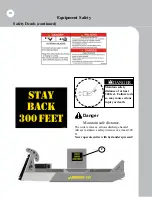
Page 10: ...stance of at least 300 feet Failure to do so may cause serious injury or death DANGER 3 0 0 Danger Maintain safe distance The cutter creates a serious discharge hazard Always maintain a safety distance of at least 300 ft Never operate cutter with bystanders present ...

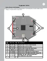
Page 11: ...t Ref No Part No Qty Description A SD 001A 2 Safety Decal Thrown object hazard B SDL 020 1 Safety Decal Lexan Combo C SD 005A 2 Safety Decal Danger Rotating blades D SD 020 2 Safety Decal Tighten Fasteners E 237 0002 2 Safety Decal High Pressure Fluid Hazard F 237 0020 2 Safety Decal STAY BACK 300 FEET Page 10 G 237 SDW2 1 DANGER DO NOT OPERATE WITHOUT SHATTERPROOF CAB DOOR A B C C D E G ...

Page 12: ... stop before dismounting Skid Loader Do not operate c u t t e r n e a r bystanders Clear work area of debris before operating DANGER Warning Parking and dismounting The rotating parts of this cutter continue to rotate even after power has been disengaged The operator should remain seated until rotation has stopped He should then set the brake turn off the engine and remove the key See skid loader ...

Page 13: ...lable Inspect fire extinguisher and check for charge daily Check first aid kit for expired contents and keep stocked Warning Check equipment before operating Tighten all nuts and bolts before operating Make certain that equipment is lowered to ground before attempting to make adjustments or perform maintenance Replace or repair any safety device bolts etc if damaged or worn Danger Stay clear of ro...

Page 14: ...ion Operate cutter only on skid loader equipped with a certified rollover protective structure ROPS Warning Slopes and rough terrain When operating on slopes or rough terrain decrease travel speed Do not operate in an area where the skid loader could roll over Be sure to fasten safety belt when operating skid loader Danger Tighten blade bolts Blade bolts will stretch with use and must be tightened...

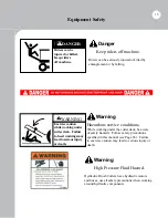
Page 15: ...e seriously injured or killed by entanglement or by falling Warning Hazardous service conditions While working under the cutter deck be aware of safety hazards Follow safety precautions specified in this manual see Page 26 Failure to exercise caution may lead to serious injury or death Warning High Pressure Fluid Hazard Hydraulic Brush Cutters have hydraulic motors and hoses use all safety precaut...

Page 16: ...e cage to prevent hazards such as thrown falling or stationary objects from entering the protective cage Be extremely careful when positioning skid loader to hitch to the equipment Caution Never allow anyone between the skid loader and the equipment during the attachment process Be certain that the cutter bearing housing has been lubricated properly and check oil level in bearing housing prior to ...

Page 17: ...ink is inserted into the retention slots of the bracket on top of the cutter fine tuning of the chain lengths may be performed by twisting the chains before securing the chains into their retention slots Lift Restriction Chains Lift Restriction Chain Attachment Points Warning Be certain that skid loader engine is stopped key is removed and all rotation of the cutter has ceased before making adjust...

Page 18: ...is normal Notice If there is enough vibration to shake the unit in a violent manner the unit should be shut down immediately Refer to the troubleshooting guide of this manual or call the factory for help at 800 633 8909 Your Brown Brush Cutter has been designed to cut anything that your properly rated skid loader can drive over grass brush small trees up to about 6 inches in diameter Any trees lar...

Page 19: ...for equipment will depend upon the height density and type of the material to be cut Consult the skid loader owner s manual to determine the engine RPM to achieve the required cutter RPM Engine RPM should not drop more than 300 RPM when cutting if this happens slow down until the specified engine RPM is maintained Dull blades will also require more power and result in lower ground speeds always be...

Page 20: ...very important to keep the cutter deck level If the cutter deck is not level its ability to cut is greatly reduced There is a tremendous amount of pressure being applied to the blades when the blades are making contact with the tree on an elevated angle The blades must be level in relationship to the ground If not level the pressure can cause the blades to bend or break possibly causing serious in...

Page 21: ...ing operations each day Make sure all blades are free swinging 7 NEVER Allow blades to make contact with rocks or stumps unit was not designed for this type of operation 8 NEVER Allow an untrained operator to operate this equipment 9 ALWAYS Install only genuine Brown replacement parts 10 ALWAYS Remain on skid loader seat until blades have stopped turning and all skid loader shut down procedures ha...

Page 22: ...TUMPS The blades will glance over the obstruction causing upwards pressure on the blades blade bar and output shaft This pressure can and will cause fatigue cracking and possible breakage of the components NEVER lower blades down onto material the same pressures will be applied to the components causing failure ...

Page 23: ...d checked twice daily during operation Every hour for the first 8 hours of use a Brown s blade bolts are designed for the extreme conditions and should not be substituted for any reason b 6 Brush Cutter blade bolts are RIGHT hand thread c Bolts and lock nuts are matched as pairs or sets do not mix d See maintenance section for proper torque specifications BLADE BAR Proper maintenance of blade bar ...

Page 24: ...r High Pressure Hose to Port A with Female Flat Face Connector Return Hose to Port B with Male Flat Face Connector Check Valve Arrow MUST point at High Pressure Hose 232 0840 Case Relief Kit MUST be installed 816 233 82027 826 233 83547 Hydraulic Motor Blade rotation is counterclockwise Brown 800 Series Hydraulic Cutter Plumbing ...

Page 25: ...ve been removed for any reason tighten blade bolts using the following procedures Repeat hourly inspections each time the blades are removed replaced Warning Follow safety guidelines listed on Page 26 of this manual when working under cutter deck Do not rely on the skid loader s lift arms to support the cutter while performing maintenance 1 Disengage Hydraulic power be certain that all rotation ha...

Page 26: ...the blades Debris found jamming or locking the blades must be removed to insure that the blade may pivot freely on the blade bolt Warning Failure to maintain freely pivoting blades can cause severe vibration or blade breakage which can result in injury or death 2 Tighten blade bolts see Page 25 for blade bolt tightening instructions and for blade bar nut tightening instructions see Page 32 Warning...

Page 27: ...eats an indention around the blade bolt hole into which the bolt shoulder will fit When this damage occurs the blade bolt will pull up into the indention when the bolt is tightened causing the blade to jam so that it can no longer pivot on the blade bolt A jammed blade will break either from fatigue or from catastrophic occurrence and will allow the blade to be ejected A blade carrier damaged in t...

Page 28: ...28 Notes ...

Page 29: ...erial from the paired blades Blades must be kept within 1 10 of a pound of each other Always keep blades in the same pairs blades across from each other as removed from the cutter NOTE Failure to keep the blades sharp will cause multiple problems including 1 Hydraulic oil overheating 2 Extreme blade bolt wear 3 Blade bar fatigue cracking and total failure 4 Blade fatigue cracking and total failure...

Page 30: ...l four blades are installed bevel up blades will be directly across 180 degrees the blade bar from each other Replacement blades are shipped in pairs by weight keep blades in pairs DO NOT MIX mount pairs across the bar from each other All blades are mounted underneath the blade bar the blade bolt is inserted from below with the nut on top of the blade bar NOTE See blade bolt tightening procedure f...

Page 31: ...ocket Step 2 Tighten bar removal tool onto output shaft threads tool must be tightened adequately to bottom out onto the bottom of the output shaft Step 3 Strike the head of the removal tool using a sledge hammer The impact of this process will unlock the tapered root spline inside the blade bar hub It may require multiple strikes to cause the spline to unlock The sound will change to a hollow sou...

Page 32: ... The hub should remain ABOVE the end of the shaft approximately 0 25 inches Step 5 Install the nut on the output shaft and tighten to approximately 300 ft lb with a 2 6 point socket Step 6 Take an 8 to 12 lb sledge hammer and hit the bottom of the blade bar several times approximately 6 inches from the hub in a circular pattern around the hub Step 7 Tighten the bar again to approximately 300 ft lb...

Page 33: ...ng a 6 point socket and appropriate torque wrench tighten the blade bar nut to 600 ft lbs torque Continue to tighten until the cotter pin slot is aligned Insert the cotter pin CAUTION Never loosen a blade bar nut to align the cotter pin hole and slot Always continue tightening the nut until they are aligned tightening up to the maximum allowable torque of 600 lb ft If alignment is still not achiev...

Page 34: ...th Hour 6th Hour 7th Hour 8th Hour Maintenance Repair Log Please record all maintenance and repair services performed on the cutter This log may help identify recurring problems with your cutter and may be requested by the manufacturer when making warranty claims Additional log pages may be copied or ordered from Brown Mfg Corp Maintenance Log 34 ...

Page 35: ...35 Maintenance Log Date Function Part s Involved Initials Maintenance Repair Log continued ...

Page 36: ...ace bearings immediately Leaking bearing housing 1 Damaged oil seal 2 Bent shaft 3 Oil seal installed incorrectly 4 Oil level too high 5 Shaft rough or pitted in oil seal area 6 Shaft bore worn in casting 7 Damaged gasket seat 8 Loose bolts 1 Replace seal 2 Replace seal and shaft 3 Replace seal 4 Drain oil to proper level 5 Replace shaft 6 Replace casting or gearbox 7 Replace silicone gasket 8 Tig...

Page 37: ...ade Tip Speed 1000 RPM 1000 RPM 1000 RPM Cutting Width 60 72 72 Bearing Housing 120 HP 120 HP 120 HP Deck Const 3 16 1 4 1 4 Deck Width 69 81 81 Weight 1 350 lbs 1 580 lbs 1 970 lbs Material Size 6 max 6 max 6 max Bearing Housing Oil Capacity in Pints 1 1 1 ...

Page 38: ...Deck Assembly All Models Replacement Parts 38 1 2 15 5 6 7 19 3 4 8 13 14 16 2 9 10 11 12 17 18 25 20 21 22 23 24 26 27 Complete Hose Kit 233 232 8200 28 29 30 ...

Page 39: ...4 NNE34FZ 6 Nylon Lock Nut 3 4 16 Zinc NF Bearing Housing to Deck 15 233 232 8200 1 Standard Flow Hose Package 16 MH 01 1 Manual Tube Holder Serial Plate Mount 17 CB5516C12Z 2 Carriage Bolt 5 16 18 x 3 4 Grade 5 Zinc For MH 01 18 NNE516CZ 2 Nylon Lock Nut 5 16 18 Zinc For MH 01 19 5 16 CHAIN 6 ft Lift Restriction Chain See Page 17 for Installation 20 233 232 8005 2 12 MBX 72 OAL 12 FJX Sleeved 21 ...

Page 40: ...Replacement Parts 40 MOTOR BEARING HOUSING 32 38 33 30 31 39 43 41 34 35 36 37 41 42 40 34 33 35 ...

Page 41: ... with the oil Make sure the motor casing is filled with oil Before starting work the hydraulic circuit should be purged of air This can be achieved by running the motor without load for 10 20 minutes during which time checks should be made for oil leaks During the first few hours of working under load checks should be made for leakages from connections and ensure that all components remain firmly ...

Page 42: ...Pin 49 235 6114 1 Output Shaft Nut Splined w Flange Castellated Blade Carrier 50 TC 133KL 4 Blade bolt kit 5 models matched bolt nut right hand thread 51 UK 905 4 Blade 5 models sold in matched sets only paired by weight 52 NB 133 Wrench Opt Blade Wrench 53 235 0011 Opt Blade Bar Removal Tool See Page 31 for Usage Instructions NS TC 133S varies Blade Bolt Shim used if blade is binding under blade ...

Page 43: ...D SERIOUS PERSONAL INJURY OR DEATH THIS ROTARY CUTTER MUST NOT BE ATTACHED TO ANY POWER UNIT THAT DOES NOT HAVE A SHATTERPROOF DOOR OR FRONT SHIELD INSTALLED Size Recommended Torque ft lbs inch Grade 5 Grade 8 Coarse Fine Coarse Fine 1 4 6 3 7 3 9 10 5 16 13 14 18 20 3 8 23 26 33 37 7 16 37 41 52 58 1 2 57 64 80 90 9 16 82 91 115 129 5 8 112 128 159 180 3 4 200 223 282 315 7 8 322 355 454 501 1 48...

Page 44: ...Version 1 3 1 January 2020 Brown 815 Cutters From Serial Number A 0 0 0 1 ...

Reviews: