
Installation Instructions
ERVBBLHA
ENERGY RECOVERY VENTILATOR
SIZES 1150 AND 1200
TABLE OF CONTENTS
PAGE
SAFETY CONSIDERATIONS
1
. . . . . . . . . . . . . . . . . . . . . . . . .
INTRODUCTION
1
. . . . . . . . . . . . . . . . . . . . . . . . . . . . . . . . . . .
INSTALLATION CONSIDERATIONS
1
. . . . . . . . . . . . . . . . . . .
COMPONENT DESCRIPTIONS
2
. . . . . . . . . . . . . . . . . . . . . . .
UNIT INSTALLATION
2
. . . . . . . . . . . . . . . . . . . . . . . . . . . . . . .
WALL CONTROL
3
. . . . . . . . . . . . . . . . . . . . . . . . . . . . . . . . . . .
ELECTRICAL CONNECTIONS
5
. . . . . . . . . . . . . . . . . . . . . . . .
ACCESSORIES
5
. . . . . . . . . . . . . . . . . . . . . . . . . . . . . . . . . . . . .
BALANCING ERV
5
. . . . . . . . . . . . . . . . . . . . . . . . . . . . . . . . . .
VENTILATION EVALUATION
6
. . . . . . . . . . . . . . . . . . . . . . . .
CONTROL BOARD OPERATION
6
. . . . . . . . . . . . . . . . . . . . . .
CARE AND MAINTENANCE
7
. . . . . . . . . . . . . . . . . . . . . . . . .
TROUBLESHOOTING
9
. . . . . . . . . . . . . . . . . . . . . . . . . . . . . . .
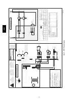
WIRING DIAGRAM
10
. . . . . . . . . . . . . . . . . . . . . . . . . . . . . . . .
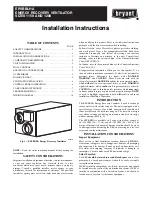
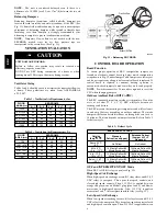
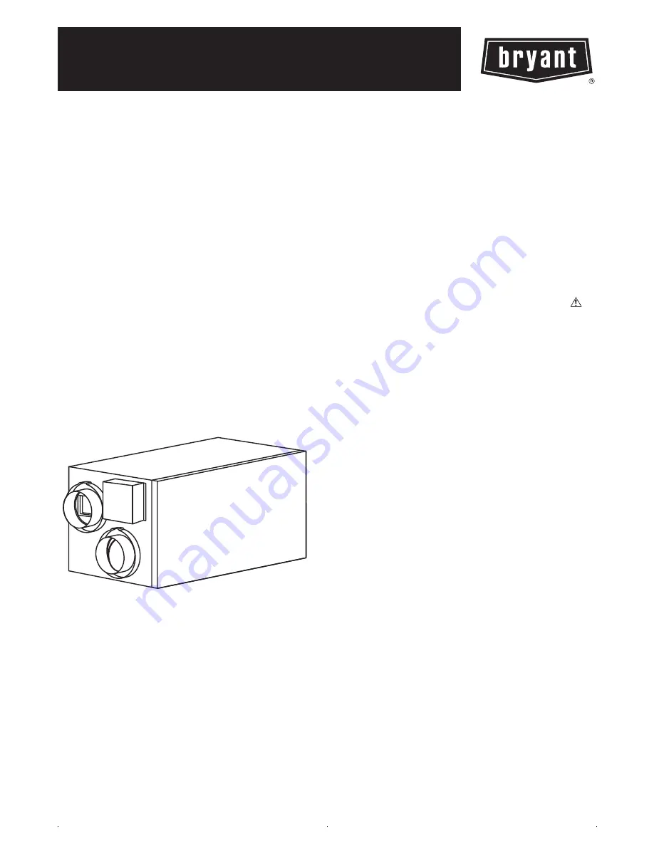
A07619
Fig. 1 -- ERVBBHA Energy Recovery Ventilator
NOTE
: Read the entire instruction manual before starting the
installation.
SAFETY CONSIDERATIONS
Improper installation, adjustment, alteration, service, maintenance,
or use can cause explosion, fire, electrical shock, or other
conditions which may cause death, personal injury or property
damage. Consult a qualified installer, service agency or your
distributor or branch for information or assistance. The qualified
installer or agency must use factory--authorized kits or accessories
when modifying this product. Refer to the individual instructions
packaged with the kits or accessories when installing.
Follow all safety codes. Wear safety glasses, protective clothing,
and work gloves. Have a fire extinguisher available. Read these
instructions thoroughly and follow all warnings and cautions
included in literature and attached to the unit. Consult local
building codes and the current edition of the National Electrical
Code (NEC) NFPA 70.
In Canada, refer to the current editions of the Canadian Electrical
Code CSA C22.1.
Recognize safety information. When you see this symbol
on
the unit and in instructions or manuals, be alert to the potential for
personal injury. Understand the signal words
DANGER
,
WARNING
, and
CAUTION
. These words are used with the
safety--alert symbol.
DANGER
identifies the most serious hazards,
which
will
result in severe personal injury or death.
WARNING
signifies hazards, which
could
result in personal injury or death.
CAUTION
is used to identify unsafe practices, which
may
result
in minor personal injury or product and property damage.
NOTE
is used to highlight suggestions which
will
result in enhanced
installation, reliability, or operation.
INTRODUCTION
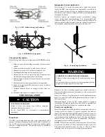
The ERVBBHA Energy Recovery Ventilator is used to exchange
indoor stale air with outside fresh air. The unit is equipped with a
special energy recovery core which transfers both sensible and
latent heat between the fresh incoming air. The cross--flow design
core allows entering and leaving air streams to transfer heat energy
without mixing. (See Fig. 2.)
The ERVBBHA is available in 2 sizes with airflow ranges of
60--148 CFM (28 -- 71 L/s), and 60--183 CFM (28 -- 89 L/s). The
design of this unit is horizontal. Special attention should be given
to duct application, balancing the ERV, and locating unit for easy
access and routine maintenance.
INSTALLATION CONSIDERATIONS
Inspect Equipment
Move carton to final installation location. Remove ERVBBHA
from carton taking care not to damage unit. Remove all packaging
and inspect unit for damage. Remove parts bag from inside unit.
File claim with shipping company if shipment is damaged or
incomplete. Check to make sure ERV unit matches Fig.1.
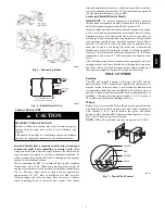
Select Location
The ERV
should be located in a conditioned space
and in close
proximity to a fused power source. It should be easily accessible
for routine maintenance.
If ERV is installed independent of a forced--air system, unit should
be located near the center of the air distribution system. If ERV is
installed in conjunction with a forced--air system, unit should be
located next to (or close to) the indoor equipment.


