
resistente a los golpes, soporta el uso y el abuso del
servicio diario y a’sla electrónicamente al usuario de
riesgos de choque eléctrico potenciales. La protección
electrónica contra sobrecargas por aplicación accidental
de tensión a los circuitos para medición de resistencia y
continuidad, combinada con su construcción reforzada,
hacen de él un instrumento duradero y confiable.
Sección 2 CARACTERÍSTICAS
• Répertorié UL selon les normes américaines
et canadiennes
• Conçu pour la catégorie II 600 V
• Tamaño de bolsillo
• Operación sencilla
• Terminales de entrada empotrados, diseñados para
brindar seguridad
• Protección contra sobrecargas en todas las escalas
• Función de prueba de diodos
• Continuidad
Sección 3 ESPECIFICACIONES
Indicador
LCD (pantalla de cristal
l’quido) de 3-1/2 dígitos,
nœmeros de 16
mm y lectura máxima de
1999 con signo automático
Indicaci—n de escala excedida
Muestra “1” como dígito
más significativo
Velocidad de muestreo
Tres veces por segundo
Ambiente para operación
0 a 50 °C, máxima
humedad relativa 80% a 31
°C, decreciendo linealmente
a 50% con 40 °C
Ambiente para almacenamiento
-20 a 60 °C con humedad
relativa inferior a 80%
Alimentación
Una pila de 9 V, apta para
transistores, N° de pieza
AWS B-4 (N° NEDA 1604)
Requisitos de potencia
Normal: 30 m
Ω
(típicos)
Vida útil de la pila
Normal: 200 horas con pila
de zinc-carbón
Fusible
N° de pieza AWS F-14; 0,2 A,
250 V, 5 x 20 mm, acción
rápida.
Dimensiones
130 (l) x 72 (a) x 28 (p) mm
Peso
Aproximadamente 146 g
con la pila
L’instrument se conforme aux installations de catégorie II
(catégorie surtension). Pour usage industriel. Niveau de
pollution 2 en conformit´avec IES-664. Altitude atteignant
2000m. Utilisation interne. Si el equipo se utiliza en una
forma no especificada, la protección provista puede quedar
reducida.
DOBLE AISLACIÓN
ADVERTENCIA: PARA EVITAR CHOQUES
ELÉCTRICOS, ANTES DE SACAR LA TAPA DE LA
PILA DESCONECTE LOS TERMINALES DE
MEDICIÓN.
PRECAUCIÓN: PARA TENER PROTECCIÓN
CONTINUA CONTRA INCENDIOS, REEMPLACE EL
FUSIBLE SOLAMENTE POR OTRO QUE
SATISFAGA LOS REQUERIMIENTOS DE TENSION,
CORRIENTE Y VELOCIDAD DE RUPTURA
ESPECIFICADOS.
Sección 4 REGLAS DE SEGURIDAD
1.
Antes de operar su multímetro digital, lea estas
instrucciones en forma completa y atenta. Preste
atención particular a las ADVERTENCIAS y a las
PRECAUCIONES que informan sobre
procedimientos potencialmente peligrosos. Estas
instrucciones deben ser respetadas.
2.
Antes de cada uso, verifique siempre que los cables
de prueba y los accesorios no tengan signos de
daño o de anormalidad. Si existe alguna condición
anormal (por ejemplo, puntas de prueba rotas, caja
rajada, pantalla sin lecturas, etc.), no intente efectuar
ninguna medición. Consulte la sección 12.
Devolución para reparaciones.
3.
Cuando emplee instrumentos eléctricos, nunca se
conecte a tierra. No toque caños metálicos expuestos,
tomacorrientes, herrajes, etc., que puedan tener igual
potencial que la tierra. Mantenga su cuerpo aislado de
tierra usando ropa seca, zapatos con suela de goma,
alfombras de goma o cualquier material aislante
aprobado.
4. Cuando intente efectuar mediciones, nunca toque
cables expuestos, conexiones o conductores de
circuitos alimentados (vivos).
5.
Nunca reemplace el fusible protector dentro del
multímetro digital por alguno que no sea la pieza con
el nœmero especificado por AWS u otro aprobado
como equivalente.
6.
Recuerde: Piense en la seguridad y actœe
seguramente.
7. Cuando pruebe si hay tensión presente, asegœrese
de que la función medición de tensión funcione
correctamente leyendo una tensión conocida en esa
gama, antes de suponer que una lectura de cero
indica una condición de sin tensión.
8.
Las calibraciones y las reparaciones sólo deben ser
efectuadas por personal de servicio calificado.
9.
No intente realizar la calibración o el servicio del
instrumento, a menos que esté presente otra
persona capaz de prestar primeros auxilios y aplicar
técnicas de reanimación.
10. No instale piezas substitutas ni efectœe
modificaciones no autorizadas en el instrumento.
Para asegurar que se mantengan las caracter’sticas
de seguridad, env’e el instrumento a A. W. Sperry
Instruments para su servicio y reparación.
11. Para evitar los choques eléctricos emplee
PRECAUCION cuando trabaje con tensiones
superiores a 40 VCC o 20 VCA. Tales tensiones
presentan riesgos de choques eléctricos.
12. No opere este instrumento en una atmósfera
explosiva (por ejemplo, en presencia de gases,
humos, vapores o polvaredas inflamables).
Sección 5 PREPARACIÓN PARA EL USO
Sección 5.1
DESEMBALAJE Y VERIFICACIÓN DEL CONTENIDO
El Instrumento se env’a completo y listo para usar.
Verifique la siguiente lista de contenido cuando lo
desembale. Si falta alguna pieza, notifique al distribuidor
a quien le compró el instrumento o a A. W. Sperry
Instruments, Inc.:
• Instrucciones de Operación N° 314.
• Puntas de prueba TL-76 (una negra y una roja)
• Pila de 9 V apta para transistores (N° de pieza
AWS B-4). Para instalarla correctamente,
vea la sección 10.2, Reemplazo de la pila.
• Un fusible de 0,5 A, 250 V, 5 x 20 mm y acción
rápida, N° de pieza AWS F-14.
(Vea la sección 10.3, Reemplazo del fusible).
Sección 5.2
PROCEDIMIENTO ANTERIOR A LA OPERACIÓN
1. Instale la pila de 9 V apta para transistores (N° de
pieza AWS F-14).
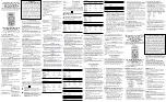
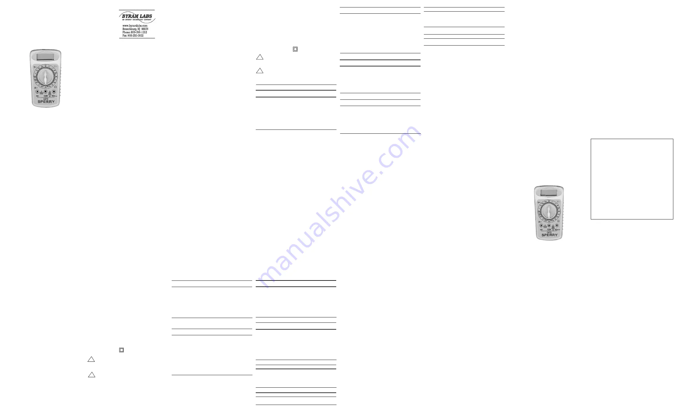
2. Inspeccione el instrumento para comprobar que no
tenga ningœn defecto externo (compárelo con el
diagrama de la página 1). Si existe alguna condición
anormal, no intente efectuar ninguna medición.
Consulte la sección 9, Mantenimiento y la sección 12,
Devolución para reparaciones.
3. Inserte las puntas de prueba en los receptáculos
hembra “COM” y “V-
Ω
”. Conecte entre sílos dos
extremos de las puntas de prueba.
4. Coloque el conmutador selector en las escalas que se
indican en la tabla que sigue. Verifique que la
respuesta del instrumento sea adecuada.
Escala
Lectura d el instrumento
600VDC (600 VCC)
000 ± 4 dígitos
200DCV (200 VCC)
00.0 ± 4 dígitos
20DCV (20 VCC)
0.00 ± 4 dígitos
2DCV (2 VCC)
0.000 ± 4 dígitos
200
Ω
(200
Ω
)
1_ _.
2K
Ω
(2 k
Ω
)
1.
20K
Ω
(20 k
Ω
)
1_.
200K
Ω
(200 k
Ω
)
1_ _.
5. Como usted puede observar, el punto decimal se
mueve a medida que se cambia la escala. La lectura
máxima del indicador es 1999. La escala de 200DCV
(200 VCC) sólo leerá realmente hasta 199,9 VCC. Se
denomina escala de 200 VCC sólo por razones de
conveniencia.
6. Ahora usted puede verificar el punto decimal para
cada escala consultando la sección 3,
Especificaciones, donde se listan las escalas.
Consulte las columnas Escala y Resolución para
computar la posición del punto decimal.
7. Si existe alguna condición anormal, no intente
efectuar ninguna medición eléctrica. En lugar de ello,
consulte la sección 12, Devolución para reparaciones.
Sección 6
REEMPLAZO DE LA PILA
El DMM tiene una fuente de alimentación interna que
consiste en una pila de 9 V apta para transistores (N°
NEDA 1604, N° de parte AWS B-4).
Advertencia
Antes de intentar reemplazar la pila, desconecte primero
las puntas de prueba de cualquier circuito alimentado y
luego desconéctelas del instrumento.
1.
Desconecte las puntas de prueba de cualquier
circuito alimentado y luego desconéctelas del
instrumento.
2.
Gire el conmutador de escalas a la posición “OFF”
(desconectado).
3.
Saque los tornillos y abra la parte posterior de la
caja del instrumento.
4.
Saque la pila de su compartimiento y desprenda su
conector.
5.
Reemplace la pila con otra de 9 V apta para
transistores (N° NEDA 1604, N° de pieza AWS B-4).
Para obtener la máxima vida de la pila, se
recomienda usar pilas del tipo celda alcalina.
6.
Para completar el reemplazo de la pila, efectœe el
procedimiento previo en orden inverso.
Sección 7
REEMPLAZO DEL FUSIBLE
En el instrumento hay instalado un fusible de 0,2 A, 250
V, 5 x 20 mm, de acción rápida, N° de pieza AWS F-14,
que se emplea para proteger las escalas de medición de
intensidad de corriente junto con otros componentes de
estado sólido.
ADVERTENCIA
Antes de intentar el reemplazo del fusible, desconecte las
puntas de prueba de cualquier circuito alimentado y
OPERATING INSTRUCTIONS
MODELS DM-210A, 220A, 230A
DIGITAL MULTIMETER
PLEASE READ THESE OPERATING
INSTRUCTIONS CAREFULLY
Misuse and or abuse of these instruments cannot be prevented by any
printed word and may cause injury and or equipment damage. Please
follow all these instructions and measurement procedures faithfully
and adhere to all standard industry safety rules and practices.
Sec. 1 DESCRIPTION
These DMMs offer a powerhouse of measurement
capability in a small self-contained housing. It is
designed for the professional at work in the field or in the
laboratory, yet simple enough to operate making it perfect
for the hobbyist too.
Safety was a prime consideration in the design of this
DMM. Housed in shock resistant ABS plastic, this
instrument stands up to the use and abuse of everyday
service, and electrically insulates the user from potential
shock hazards. Electronic overload protection against
accidental application of voltage to resistance and
continuity circuits, combined with it's rugged construction
make it durable and reliable instrument.
Sec. 2 FEATURES
• UL listed to both US and Canadian standards
• Designed to Cat. II 600V
• Pocket-size
• Simple operation
• Recessed safety designed input terminals
• Overload protection on all ranges
• Diode test function
• Continuity
Sec. 3 SPECIFICATIONS
Display:
3-1/2 digit LCD, 0.625"
numerals, maximum
reading1999 with automatic
sign.
Overange Indication:
"1" most significant digit
shows.
Sampling Rate:
3 times per second.
Operating Environment: 0° to 50°C (32° to 122°F), Max
RH 80% to 31°C decreasing
linear to 50% RH at 40°C.
Storage Environment:
-20° to 60°C (-4° to 140°F) at
<80% relative humidity.
Power Source:
One (1) 9V Transistor Type
Battery AWS Part #B-4
(NEDA #1604).
Power Consumption:
30mW typical.
Battery Life:
200 hours typical with zinc
carbon.
Fuse:
Part F-14; 0.2A, 250V,
5x20mm, fast acting.
Dimensions:
5.1"H x 2.8"W x 1.1"D
(130 x 72 x 28 mm).
Weight:
Approximately 5.0 oz. (146g)
including battery.
Instrument complies with insulation category (over voltage
category) II. Industrial use. Pollution degree 2 in
accordance with IEC-664. Altitude up to 2000M. Indoor
use. If the equipment is used in a manner not specified,
the protection provided by the equipment may be impaired.
DOUBLE INSULATION
WARNING: TO AVOID ELECTRIC SHOCK DIS
CONNECT MEASURING TERMINALS BEFORE
REMOVING BATTERY COVER.
CAUTION: FOR CONTINUED PROTECTION
AGAINST FIRE, REPLACE ONLY WITH FUSE OF
THE SPECIFIED VOLTAGE, CURRENT AND
RUPTURE SPEED RATINGS.
RANGES:
Sec. 4 SAFETY RULES
1.
Read these operating instructions thoroughly and
completely before operating your DMM. Pay particular
attention to WARNINGS and CAUTIONS which will
inform you of potentially dangerous procedures.
These instructions must me followed.
2.
Always inspect your DMM, test leads and accessories
for any sign of damage or abnormally before every
use. If any abnormal conditions exist (e.g. broken
test leads, cracked cases, display not reading, etc.),
do not attempt to take any measurements. Refer to
section 12 Return for Repair.
3.
Never ground yourself when taking electrical
measurements. Do not touch exposed metal pipes,
outlets, fixtures, etc., which might be at ground
potential. Keep your body isolated from ground by
using dry clothing, rubber shoes, rubber mats, or any
approved insulating material.
4.
Never touch exposed wiring, connections or any
live circuit conductors when attempting to take
measurements.
5.
Never replace the protective fuse inside the DMM
with any other than the AWS Part number specified or
approved equal.
6.
Remember: Think Safety and Act Safely.
7.
When testing for the presence of voltage, make sure
the voltage function is operating properly by reading a
known voltage in that range before assuming that a
zero reading indicates a no-voltage condition.
8.
Calibration and repair should be performed by
qualified maintenance personnel only.
9.
Do not attempt calibration or service unless another
person, capable of rendering first aid and
resuscitation is present.
10.
Do not install substitute parts or perform any
unauthorized modification of the instrument. Return
the instrument to A.W. Sperry Instruments for service
and repair to insure that safety features are
maintained.
11.
To avoid electric shock use CAUTION when working
with voltages above 40Vdc or 20Vac. Such voltages
pose a shock hazard.
12.
Do not operate this instrument in an explosive
atmosphere (i.e. in the presence of flammable gases or
fumes, vapor or dust).
Sec. 5 PREPARATION FOR USE
Sec. 5.1 UNPACKING AND CONTENTS CHECK
The DMM’s come complete and ready to use. Check the
following contents list when unpacking. If any pieces are
missing notify the distributor you purchased the
instrument from or A.W. Sperry Instruments, Inc.
• Operating Instructions #314
• Test Leads TL-76 (one black, one red)
• 9V Transistor Type Battery (AWS Part #B-4)
• One Fuse installed
Sec. 5.2 PRE-OPERATION PROCEDURE
1. Install the 9V transistor type battery.
2. Inspect the instrument for any external defects by
comparing with the diagram on page 1. If any
abnormal conditions exist, do not attempt to take any
measurements. Refer to sections 9 (Maintenance) and
12 (Return for Repairs).
3. Insert the test leads into the "COM" and "V-
Ω
" jacks.
Connect the two ends of the test leads together.
4. Place the range selector switch into the off position.
Nothing will appear on the display. Place the range
selector switch into the following ranges shown in the
chart below. Check for the appropriate meter response.
Range
Display Reading
600DCV
000
+/-4 digits
200DCV
00.0
"
20DCV
0.00
"
2DCV
.000
200
1_ _.
2K 1.
20K
1_.
200K
1_ _.
5. As you can see, the decimal point moves as the
ranges are changed. The maximum display reading is
1999. The 200DCV range will actually only read
199.9Vdc. We call this the 200DCV range for
convenience only.
6. You can now check the decimal point on each range
by referring to sec. 3 Specifications where the ranges
are all listed. Refer to the Range and Resolution
columns to compute the decimal point location.
7. If any abnormal conditions exist, do not attempt to
take any electrical measurements. Instead refer to
sec. 12 Return for Repairs.
Sec. 6 BATTERY REPLACEMENT
The DMM’s have a self-contained power supply
consisting of One 9V Transistor Type Battery (NEDA
#1604, AWS Part #B-4).
WARNING
Before attempting to replace the battery, first disconnect
the test leads from any energized circuit and then
disconnect the test leads from the instrument.
1. Disconnect the test leads from any energized circuit
and then from the instrument.
2. Turn the range switch to the "OFF" position.
3. Remove screws and open the back case.
4. Remove the battery from the compartment and unsnap
the battery connector.
5. Replace the battery with a 9V transistor type battery
(NEDA #1604), AWS Part #B-4. For maximum battery
life, alkaline cells are recommended.
6. Reverse the above procedure to complete battery
replacement.
Sec. 7 FUSE REPLACEMENT
A 0.2A, 250V, 5 x 20mm fast acting fuse, AWS Part #F-14
is installed in the instrument and used to protect the
ampere ranges along with other solid state components.
WARNING
Before attempting to replace the fuse, disconnect the test
leads from any energized circuit and then disconnect the
test leads from the instrument. Replace the fuse the
AWS Part F-14 or approved equal only. Always use fast
acting, high interrupting type fuses
1. Disconnect the test leads from any energized circuit
and then from the instrument.
2. Turn the range selector switch to the "OFF" position.
3. Remove screws and open the back case.
4. Remove the fuse from the clip on the end of the PCB.
5. Install the replacement fuse being certain it meets the
AWS Part F-14 specifications.
6. Replace the back case.
Sec. 8 OPERATION
Before making any measurements always examine the
instrument and accessories used with the instrument for
damage, contamination (excessive dirt, grease, etc.) and
defects. Examine the test leads for cracked or frayed
insulation and make sure the lead plugs fit snugly into the
instrument jacks. If any abnormal conditions exist do not
attempt to make any measurements. Instead refer to
sec.14 Return for Repairs.
Sec. 8.1 VOLTAGE MEASUREMENTS
1. Insert the black and red test leads into the respective
"COM" and "V-
Ω
" jacks.
2. Place the range selector switch into the
600DCV/600ACV position if a dc voltage is to be
measured or into the position if an ac voltage is to be
measured. Always start in the highest range of the
function to be measured.
CAUTION
To avoid possible electric shock, instrument damage
and/or equipment damage, do not attempt to take any
voltage measurements if the voltage is above 600Vdc or
if the voltage is unknown. 600Vdc is the maximum
voltages that this instrument is designed to measure.
The "COM" terminal potential should not exceed 600V
measured to ground.
3. Apply the test leads to the two points at which the
voltage reading is to be taken. Be careful not to touch
any energized conductors with any parts of your body.
4. Turn the range selector switch to the next lower range
for a more accurate reading only if the reading is
within that next lower range.
5. When measurements are completed, disconnect the
test leads from the circuit under test. Remove the test
leads from the instrument.
Sec. 8.2 CURRENT MEASUREMENTS
1. Insert the black and red test leads into the respective
"COM" and "mA" terminals.
2. Place the function switch to the 200mA position.
Always start with the highest range of the function to be
measured.
CAUTION
Do not attempt to take a current measurement if the
current is unknown or above 200mA. The "COM"
terminal potential should not exceed 500V measured to
ground.
3. Completely de-energize the circuit in which the current
is to be measured. Place the DMM in series with
the conductor carrying the current which is to be
measured. Energize the circuit.
CAUTION
Before changing ranges, always de-energize the circuit
completely. An open circuit exists between the test leads
during range change on the DMM.
CAUTION
The mA ranges are fuse protected. To avoid possible
electrical shock, instrument damage and/or equipment
damage do not:
1. Attempt to take mA current readings on circuits having
more than 200mA current flow.
2. Impress a voltage between the "COM" and "mA"
terminals exceeding 250Vac/dc. Some circuit damage
may result for voltages below 250Vac/dc.
3. Raise the "COM" terminal potential above 500V to
ground.
4. Energize the circuit. If the reading is within the next
lower range, switch to that range after completely de-
energizing the circuit under test. Continue changing to
lower ranges if the reading is within the next lowest
range to obtain the best accuracy.
5. Completely de-energize the circuit before removing the
test leads.
Sec. 8.3 RESISTANCE AND DIODE MEASUREMENTS
1. Insert the black and red test leads into the respective
"COM" and "V-
Ω
" terminals.
2. Place the range selector switch into the
Ω
range
desired for a measurement. (The test range measures
resistance from 000 up to 1999 and is used to test the
forward resistance value of diodes.
The diode check entails injecting a given current into
the diode juction to be tested and reading the voltage
drop across the diode.
CAUTION
All resistance and diode measurements should be taken
on de-energized circuits only. To avoid possible electrical
shock, instrument damage and/or equipment damage do
not connect the "COM" and "V-
Ω
" terminals to circuits
having a potential difference exceeding 250Vdc/ac. Do
not connect the "COM" terminal to potentials exceeding
500V to ground.
3. Completely de-energize the circuit or device which is
to be measured. Connect the test leads to the device
(the red test lead is positive with respect to the black
test lead). When measuring a diode, connect the "V-
Ω
" terminal to the anode. A reading of indicates an
overrange condition. This will occur with the test
leads open on all resistance ranges. If overrange
occurs when taking a reading, switch to the next highest
range.
NOTE: On the diode test range, a [1] reading indicates a
resistance greater than 2K which normally means a
defective open circuit diode. Be certain the diode anode
is connected to the V-
Ω
terminal.
Sec. 8.4 BATTERY TEST MEASUREMENTS
1. Insert the black and red test leads into the respective
“COM” and “V” terminals for 1.5Vdc and 9Vdc.
2. Place the range selector switch into the 1.5V or 9V
battery test range.
CAUTION
To avoid electric shock, instrument damage and/or
equipment damage, do not exceed 10Vdc while set to
take measurements in the battery test range.
3. Connect the test leads to the 1.5Vdc battery under
test. Normally a good 1.5Vdc battery will read above
80.0mA. Normally a good 9Vdc battery will read
above 22.0mA. Consult the battery manufacturer for
complete battery specifications to determine actual
battery life remaining and condition of battery.
Sec. 9 MAINTENANCE
Maintenance consists of periodic cleaning, battery
replacement, fuse replacement and recalibration.
Sec. 9.1 CLEANING
The exterior of the instrument can be cleaned with a soft
clean dry cloth to remove any oil, grease or grime from
the exterior of the instrument. Never use liquid solvents
or detergents. If the instrument gets wet for any reason,
dry the instrument using low pressure "clean" air at less
than 25 PSI. Use care and caution around the LCD
display protector and areas where water or air could enter
the interior of the instrument while drying.
Sec. 10 ACCESSORIES
The following accessory is available C-37 Carrying Case
Sec. 11 CALIBRATION
Calibration on these meters should be performed every
year. This can be done by sending the instruments
prepaid to:
A.W. Sperry Instruments, Inc.
Customer Service Department
245 Marcus Blvd.
Hauppauge, NY 11788
Specify in writing that calibration is necessary. The
instrument will be returned to you normally within one
week. Estimates will be furnished upon request.
CAUTION
The following procedures should performed by persons
trained and qualified in electronics and electronic
equipment service. DO NOT attempt this procedure if
not qualified.
WARNING
Do not attempt calibration or service unless another
person capable of rendering first aid and resuscitation is
present.
Sec. 12 RETURN FOR REPAIRS
Before returning your digital multimeter for repair be sure
to check that the failure to operate properly is not due to
the following:
1. Weak battery
2. Open fuse
3. Open, loose or intermittent test leads
If these conditions do not exist and the instrument fails to
operate properly, return the instrument and accessories
prepaid to:
A.W. Sperry Instruments, Inc.
Customer Service Department
245 Marcus Blvd.
Hauppauge, NY 11788
State in writing what is wrong with the instrument. All
warranty repairs must include proof of purchase in the
form of a legible original copy of the sales receipt clearly
identifying the distributor, model number and date of
purchase. Repair estimate will be furnished if requested
for out of warranty instruments. Be sure to include all
accessories which may be related to the problem and a
note describing the malfunction you observed.
4/02
Formulario N° 314
INSTRUCCIONES DE OPERACIÓN
MODELO DM-210A, 220A, 230A
MULTIMETRO DIGITAL
POR FAVOR LEA ESTAS
INSTRUCCIONES DE OPERACIÓN
CUIDADOSAMENTE
El mal uso o abuso de estos instrumentos no puede ser evitado
mediante ninguna instrucción escrita y puede causar lesiones y/o
daños al equipo. Por favor siga fielmente estas instrucciones y los
procedimientos de medición y aplique todas las normas y prácticas
de seguridad industriales estándar.
A.W. SPERRY INSTRUMENTS INC.
The Professional’s Choice™
245 MARCUS BLVD., HAUPPAUGE, NY 11788
ESTADOS UNIDOS
Teléfono: Llamadas sin cargo 1-800-645-5392
o con cargo el 1-631-231-7050
Fax:1-631-434-3128
Email: cat@awsperry.com www.awsperry.com
DEVOLUCÍON EN GARANTÍA
Para obtener instrucciones completas, consulte la
Sección “Devolución para reparaciones”. Todas las
devoluciones deben incluir una copia legible o el original
de la boleta de compra donde se identifiquen claramente
el nœmero de modelo, el nœmero de serie y la fecha de
compra.
Sección 1 DESCRIPCÍON
Este instrumento ofrece una poderosa habilidad de
medición dentro de un alojamiento pequeño. Está
diseñado para el profesional que trabaja en el terreno o
en el laboratorio, pero es suficientemente simple de
operar, por lo que resulta ideal para el aficionado. La
seguridad fue una consideración primordial en su diseño.
Este instruento está alojado en una caja de plástico ABS
!
!
GARANTÍA
GARANTÍA LIMITADA DE UN AÑO
A. W. Sperry Instruments, Inc. certifica que este instrumento
AWS fue cuidadosamente verificado e inspeccionado y que
está garantizado por el término de un (1) año desde la fecha
de adquisición por parte de comprador final original, y que el
instrumento no haya sido empleado erróneamente, dañado
por negligencia, reparación indebida o no autorizada, o por el
uso abusivo o contrario a las instrucciones de operación. Los
instrumentos y los comprobantes de la compra, en la forma
de una copia legible o el original de la boleta de venta que
identifique claramente distribuidor, nœmero del instrumento y
fecha de la compra, deben ser devueltos a: A. W. Sperry
Instruments, Inc., Attention: Customer Service Center, 245
Marcus Boulevard, Hauppauge, NY 11788, Estados Unidos,
con franqueo postal pago, para que se examine el defecto de
fabricación cubierto por la garantía. A. W. Sperry Instruments,
Inc. será quien decida exclusivamente la naturaleza de tal
defecto. La responsabilidad de A. W. Sperry Instruments, Inc.
está limitada a la reparación o el reemplazo, a su propia
opción, de cualquier producto defectuoso.
NOTA: El per’odo de calibración recomendado no debe
exceder un año. El costo del servicio de calibración no está
cubierto por los términos y las condiciones de la garantía.
DC Voltage
19 Range, 6 Function
15 Range, 6 Function 11 Range, 4 Function
DM-230A
DM-220A
DM-210A
Range
200mV/2/20/
2/20/200/600V
2/20/200V
200/600V
Basic
Accuracy
0.50%
1.50%
1.50%
Resolution
100 uV
1mV
1mV
Input
Impedance
10 Mohm
10 Mohm
10 Mohm
Overload
Protection
600VDC or peak AC on all ranges
Diode Test
DM-230A
DM-220A
DM-210A
Test Current 1 +/- .6 mA
1 +/- .6 mA
1 +/- .6 mA
Test
6V
Voltage
(MICROWAVE 3.2V
3.2V
DIODE)
Battery Test
DM-230A
DM-220A
DM-210A
Battery Test
DM220A
1.5V/9V
AC Voltage
19 Range, 6 Function
15 Range, 6 Function 11 Range, 4 Function
DM-230A
DM-220A
DM-210A
Range
200/600V
200/600V
200/600V
Basic
Accuracy
1.50%
1.50%
1.50%
Resolution
100mV
100mV
100mV
Input
Impedance
10 Mohm
10 Mohm
10 Mohm
Response
Frequency
Response
50-60 Hz
50-60 Hz
50-60 Hz
Overload
Protection
600VDC or peak AC on all ranges
DC Current
19 Range, 6 Function
15 Range, 6 Function 11 Range, 4 Function
DM-230A
DM-220A
DM-210A
Range
0-20u/200uA/2m/
20m/200mA
Basic
Accuracy
1.50%
Resolution
10nA
Overload
200mA/250V
Protection fuse glass fuse
Resistance
19 Range, 6 Function
15 Range, 6 Function 11 Range, 4 Function
DM-230A
DM-220A
DM-210A
Range
0-200/2K/20K/
0-200/2K/20K/
0-200/2K/20K/
200K/2M
200K/2M
200K/2M
Basic
Accuracy
1.50%
1.50%
1.50%
Resolution
0.1 ohm
0.1 ohm
0.1ohm
Overload
Protection
250 VDC or Peak AC on all ranges
Tensíon Continua
Rango 19, 6 Funciones
Rango 15, 6 Funciones Rango 11, 4 Funciones
DM-230A
DM-220A
DM-210A
Rango
200mV/2/20/
2/20/200/600V
2/20/200V
200/600V
Precisión
Básica
0.50%
1.50%
1.50%
Resolución
100 µ V
1 µ V
1 µ V
Impedancia
de Entrada 10 Mohmios
10 Mohmios
10 Mohmios
Protección
Contra
600VCC o CA Pico por 1 min
Sobrecarga
!
!
Tensíon Alterna
Rango 19, 6 Funciones
Rango 15, 6 Funciones Rango 11, 4 Funciones
DM-230A
DM-220A
DM-210A
Rango
200/600V
200/600V
200/600V
Precisión
Básica
1.50%
1.50%
1.50%
Resolución
100mV
100mV
100mV
Impedancia
de Entrada 10 Mohmios
10 Mohmios
10 Mohmios
Frequency
Response
50-60 Hz
50-60 Hz
50-60 Hz
Protección
Contra
600VCC o CA Pico por 1 min
Sobrecarga
Corriente Continua
Rango 19, 6 Funciones
Rango 15, 6 Funciones Rango 11, 4 Funciones
DM-230A
DM-220A
DM-210A
Rango
0-20u/200uA/2m/
20m/200mA
Precisión
Básica
1.50%
Resolución
10nA
Protección 200mA/250V
Contra
fuse glass
Sobrecarga
fuse
Resistance
Rango 19, 6 Funciones
Rango 15, 6 Funciones Rango 11, 4 Funciones
DM-230A
DM-220A
DM-210A
Rango
0-200/2K/20K/
0-200/2K/20K/
0-200/2K/20K/
200K/2M
200K/2M
200K/2M
Precisión
Básica
1.50%
1.50%
1.50%
Resolución
0.1 ohmios
0.1 ohmios
0.1ohmios
Protección
Contra
250 VCC o CA Pico por 1 min
Sobrecarga
Diodo
DM-230A
DM-220A
DM-210A
Corriente
1 +/- .6 mA
1 +/- .6 mA
1 +/- .6 mA
de Prueba
Tensión
6V
de Prueba
(Diodo de
3.2V
3.2V
Microondas)
Prueba de Bateria
DM-230A
DM-220A
DM-210A
Prueba
DM220A
de Bateria
1.5V/9V
Byram
Labs


