background image

Service Manual

PX Q

MADE IN GERMANY

Print Module

Summary of Contents for PX Q4.3L

Page 1: ...Service Manual PX Q MADE IN GERMANY Print Module...

Page 2: ...r development of our products discrepancies between documentation and product can occur Please check www cab de for the latest update Terms and conditions Deliveries and performances are effected unde...

Page 3: ...asuring and Adjusting the Winding Torques 16 5 1 1 Measuring the Winding Torques 16 5 1 2 Adjusting the Winding Torques 18 5 2 Adjusting the Printing Mechanism 19 5 2 1 Preparing the Printer for Adjus...

Page 4: ...ction Reference to section position illustration number or document Option accessories peripheral equipment special fittings Time Information in the display 1 2 General Safety Instructions This servic...

Page 5: ...ng power units Working in the immediate vicinity of open power supply components Mechanical check of power supply components Modifying circuits in the device Test the zero potential of the device part...

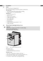
Page 6: ...Cylindrical dynamometer spring scale 0 10 N Digital circuit analyzer 2 2 Removing and Installing the Rear Cover Attention The rear cover or cables can be damaged via careless handling X Move cable out...

Page 7: ...scharged 1 Unplug the device from the electrical outlet and remove the rear cover 2 Remove the material from the printer 3 Disconnect the cable 4 from the connector 5 of the label sensor 3 4 Loosen th...

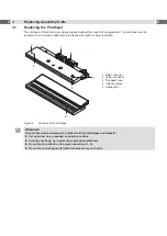
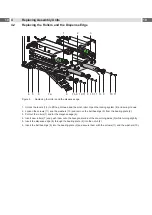
Page 8: ...lution 1 2 3 4 3 4 5 1 Data connector 2 Power connector 3 Threaded holes 4 Catching holes 5 Heating line Figure 3 Structure of the printhead Attention The printhead can be damaged by static electricit...

Page 9: ...rst unplug the power cable 8 followed by the data cable 7 Mounting the Printhead 1 First connect the data cable 7 followed by the power cable 8 2 Place the printhead into the printhead assembly and in...

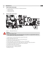
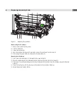
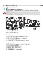
Page 10: ...stem 8 and swing it down 2 Loosen the screws 11 and the washers 10 and remove the ball bearings 9 from the bearing plate 2 3 Pull out the rollers 7 and or the dispense edge 6 4 Insert new rollers 7 an...

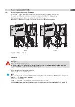
Page 11: ...gure 6 Slipping clutches Preparation Danger Risk of death via electric shock X Before opening the rear cover disconnect the device from the mains supply and wait at lease one minute until the power su...

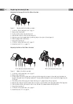
Page 12: ...without automatic ribbon saver PX Q with automatic ribbon saver Figure 8 Brake at the ribbon unwinder 1 PX QR Lift the electronics unit page 11 2 Remove the snap ring 7 3 Pull the brake 6 from the win...

Page 13: ...sensor Removing the label sensor 1 Unplug the device from the electrical outlet and remove the rear cover 2 Remove the material from the printer 3 Disconnect the cable 4 from the connector 5 of the l...

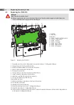
Page 14: ...n Manual 2 Unplug the printer from the electrical outlet 3 Detach all interface cables from the back of the printer 4 Remove all memory media from the slots 5 Dismount the rear cover 6 Unplug all plug...

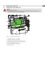
Page 15: ...inute until the power supply unit has discharged 1 1 2 1 3 1 1 1 Figure 11 Replacing the power supply unit 1 Dismount the PCB CPU 4 5 on page 14 2 Unplug the cable from the connectors 3 3 Loosen 6 scr...

Page 16: ...e coupling torque and the torque of the brake Only the torque of the brake is measured when the winding axis is rotating in the winding direction For this reason measurements of the torques at the rew...

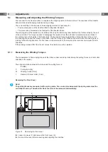
Page 17: ...il the power supply unit has discharged 1 Unplug the printer from the electrical outlet 2 Remove the rear cover 2 2 on page 6 3 Remove the transfer ribbon from the printer 4 Attach the test collar 3 t...

Page 18: ...minute until the power supply unit has discharged 2 1 Figure 14 Adjusting the winding torque 1 Unplug the printer from the electrical outlet 2 Remove the rear cover 2 2 on page 6 3 Press the knurled...

Page 19: ...ns Adjustment of the printing mechanism comprises the following procedures in the order specified 1 Preparing the printer for adjustment 5 2 1 on page 19 2 Aligning the printhead to the print roller 5...

Page 20: ...of damage Attempting to adjust the printhead when the fixing screws 1 are tight can lead to defects at the printhead assembly X Always loosen the fixing screws 1 before adjusting the printhead i Note...

Page 21: ...figuration Manual or a similar print pattern 4 Adjust the adjustment screw 1a or 1b clockwise in small increments on the side with the weaker print image until the print image is even across the entir...

Page 22: ...lear resistance when turning the adjustment screw 4 you may only continue turning the screw in very small increments but no more than one eighth of a turn X Only turn the adjustment screw 4 as far as...

Page 23: ...Unplug the printer from the electrical outlet 2 Remove the rear cover 2 2 on page 6 3 Loosen screw 3 of the belt tension bracket 2 to adjust the tension of belt 5 between motor and print roller 4 4 Sw...

Page 24: ...m the mains supply and wait at lease one minute until the power supply unit has discharged 1 3 2 4 Figure 21 Adjusting the head switches 1 Unplug the printer from the electrical outlet 2 Remove the re...

Page 25: ...PX QL PX QR Figure 22 Checking the eccentrics position 1 Remove the label material 2 Lock the printhead 3 Switch on the printer The ribbon saver will be synchronized After this the eccentrics are in...

Page 26: ...ply and wait at lease one minute until the power supply unit has discharged 4 2 3 1 Figure 23 Adjusting the magnetic clutch 1 Unplug the printer from the electrical outlet 2 Remove the rear cover 3 Lo...

Page 27: ...ter and computer match For an Ethernet connection check the validity of the IP address and the subnet mask Check the interface cable and replace it if necessary If all functionality of the interface h...

Page 28: ...28 28 7 Block Diagram Figure 24 Block diagram PX Q...

Page 29: ...R85 A 1 14 B C D E F G H J K L M N P U7 R305 C237 C239 R155 C241 C245 X1 1bot 1top CON3 1 CON4 R72 R74 R122 B5 B6 K H1 K H4 K H5 K H6 K H7 C205 C255 C256 B1 B2 B3 B4 D5 P1 P2 CD P3 P4 P5 P6 P7 P8 P9 G...

Page 30: ...acement 13 M Magnetic clutch 26 Motor 23 P PCB CPU 29 PCB CPU replacement 14 Power supply replacement 15 Printhead position 20 Printhead pressure adjustment 21 Printhead replacement 8 Print image 19 R...

Reviews: