background image

©2013 CADEL srl | All rights reserved – tutti i diritti riservati

it

stufA A pELLEt

manuale


di


installazione

uso


e


manutenzione

en

pELLEt stovE

installation

use


and


maintenance

fr

poêLE à grAnuLés

manuel


d

installation

utilisation


et


entretien

es

EstufA DE pELLEts

manual


de


instalación

uso


y


manutención

nl

pELLEtkAChEL

handleiding


voor


installatie

gebruik


en


onderhoud

pt

EstufAs A pELLEt

manual


para


instalação

uso


e


manutenção

el

ΣΟΜΠΕΣ PELLET

εγκατασταση

χρηση


και


συντηρηση

venus

 - 

gioia

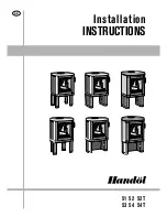
Summary of Contents for VENUS

Page 1: ...e en pellet stove installation use and maintenance fr po le granul s manuel d installation utilisation et entretien es estufa de pellets manual de instalaci n uso y manutenci n nl pelletkachel handlei...

Page 2: ......

Page 3: ...I 29 10 11 SPEGNIMENTO 29 10 12 IMPOSTAZIONI OROLOGIO 29 10 13 PROGRAMMAZIONE GIORNALIERO 30 10 14 PROGRAMMAZIONE WEEK END 30 10 15 PROGRAMMAZIONE SETTIMANALE 30 10 16 REGOLAZIONE VENTOLE 31 10 17 SPE...

Page 4: ...ista Specializzato I simboli di ATTENZIONE indicano una nota importante UTENTE UTILIZZATORE TECNICO AUTORIZZATO da intendersi ESCLUSIVAMENTE o il Costruttore della stufa o Tecnico Autorizzato del Serv...

Page 5: ...restazione disponibile online ai siti www cadelsrl com www free point it 3 AVVERTENZE Tutte le illustrazioni riportate nel manuale hanno un mero scopo esplicativo ed indicativo e potrebbero pertanto d...

Page 6: ...to del suo utilizzo e per qualsiasi futuro spostamento movimentare la stufa con mezzi idonei prestando attenzione alle norme vigenti in materia di sicurezza non capovolgere e o ribaltare su un lato la...

Page 7: ...n regolare funzionamento di un apparecchio riscaldante essenziale che la canna fumaria sia costruita a regola d arte e mantenuta sempre in perfetta efficienza La canna fumaria deve essere singola vedi...

Page 8: ...solanti Verificare la distanza dal produttore del camino L imbocco del camino deve essere nello stesso locale in cui installato l apparecchio o tutt al pi nel locale attiguo e avere al disotto dell im...

Page 9: ...a In caso di dubbi applicare sempre le normative pi ristrettive Far controllare e pulire la canna fumaria e il comignolo da uno spazzacamino esperto almeno una volta l anno Lo spazzacamino dovr rilasc...

Page 10: ...Componenti camino LEGENDA Fig 6 a pag 10 1 Comignolo 2 Via di efflusso 3 Condotto fumario 4 Isolamento termico 5 Parete esterna 6 Raccordo del camino 7 Canale da fumo 8 Generatore calore 9 Portina d i...

Page 11: ...biti a camere da letto rimesse garage magazzini di materiali combustibili La presa d aria deve avere una superficie netta totale minima di 80 cm2 la suddetta superficie va aumentata se all interno del...

Page 12: ...necessario verificare le distanze minime necessarie alla presa d aria comburente poich per esempio una finestra o porta aperta provocano un vortice che pu sottrarre l aria comburente necessaria alla...

Page 13: ...re tubo in lamiera specifico ad uso fumisteria di 80 mm o 100 mm a seconda della tipologia dell impianto con guarnizioni siliconiche vietato l impiego di tubi metallici flessibili in fibrocemento o di...

Page 14: ...foratura per il passaggio del tubo maggiorata Fig 11 Esempio 2 LEGENDA Fig 11 a pag 14 1 Isolante 2 Tappo d ispezione 3 Portina d ispezione caminetto 4 Distanza minima di sicurezza 0 5 mt 5 Inclinazi...

Page 15: ...uato provoca una cattiva combustione frequente intasamento del braciere intasamento condutture di scarico aumenta il consumo e diminuisce la resa calorica sporca il vetro aumenta la quantit di cenere...

Page 16: ...urente Verificare l eventuale presenza di altre stufe o apparecchiature che mettano la stanza in depressione vedi PRESA D ARIA ESTERNA a pag 11 Verificare a stufa accesa che nel locale non vi sia la p...

Page 17: ...D INGOMBRO Fig 13 Dimensioni generali LEGENDA Fig 13 a pag 17 1 64 5 cm 2 107 5 cm 3 53 5 cm 4 27 3 cm 5 28 5 cm 6 15 cm 7 7 5 cm 8 99 6 cm 9 35 1 cm 10 Presa aria comburente d 6 cm 11 Scarico fumi d...

Page 18: ...4 a pag 18 Per le norme di sicurezza antincendio si devono rispettare le distanze da oggetti infiammabili o sensibili al calore divani mobili rivestimenti in legno ecc come riportato in Fig 14 a pag 1...

Page 19: ...ti superiori e le viti posteriori vedi Fig 15 a pag 19 e Fig 16 a pag 19 Fig 17 Rimozione profili curvi superiori Fig 18 Supporti da piegare Rimuovere i 2 profili curvi superiori vedi Fig 17 a pag 19...

Page 20: ...19 a pag 20 Avvitare i profili curvi superiori vedi Fig 20 a pag 20 9 5 ASSEMBLAGGIO PANNELLI MODELLO GIOIA E obbligatorio far eseguire tutte le operazioni di assemblaggio da un tecnico autorizzato Pe...

Page 21: ...llo in modo che sia appoggiato stabilmente nelle viti anteriori e posteriori vedi Fig 25 a pag 21 9 6 ALLACCIAMENTO ELETTRICO Importante l apparecchio deve essere installato da un tecnico autorizzato...

Page 22: ...ggiato deve essere sostituito da un tecnico autorizzato Quando la stufa non viene utilizzata per lunghi periodi consigliabile rimuovere la spina dalla presa elettrica a parete 9 7 ALLACCIAMENTO TERMOS...

Page 23: ...ere il coperchio superiore come descritto nelle pagine precedenti Fig 28 Posizionamento tubi superiore Fig 29 Canalizzazione superiore 1 possibile far uscire l aria calda superiormente alla stufa vedi...

Page 24: ...6 metri di tubo possiamo avere una portata di aria variabile da minimo 30 m3 h ad un massimo di 80 m3 h ed una temperatura aria che varia da un minimo di 50 C ad un massimo di 80 C Questi valori sono...

Page 25: ...re le indicazioni sotto riportate L accensione del pellets avviene molto facilmente se l installazione corretta e la canna fumaria efficiente Accendere la stufa a Potenza 1 per almeno 2 ore per permet...

Page 26: ...a dei fumi allo scarico Entrambi hanno funzioni di programmazione P3 consente di accedere al set di temperatura ed al men dei parametri Utente e Tecnico P4 accensione e spegnimento sblocco da eventual...

Page 27: ...a pag 29 3 SET CRONO Premere una volta il tasto P3 appare la scritta ABILITA CRONO Premere ancora P3 e tramite i tasti P1 e P2 mettere in OFF o ON Per la programmazione giornaliera del week end o sett...

Page 28: ...sufficientemente alta dopo circa 7 10 minuti si ritiene avvenuta l accensione e sul display compare FUOCO PRESENTE Terminata la fase FUOCO PRESENTE la centralina si pone in modalit di LAVORO visualizz...

Page 29: ...condi la stufa entra nella fase di ATTESA RAFFRED Terminata la fase di raffreddamento riparte automaticamente con le varie fasi vedi AVVIAMENTO a pag 28 10 9 SET TEMPERATURA Per modificare la temperat...

Page 30: ...to nei giorni di sabato e domenica Premere il tasto P3 e poi il tasto P5 fino ad evidenziare il men 03 SET CRONO Premere una volta il tasto P3 e tramite i tasti P5 e P6 selezionare la scritta PROGRAM...

Page 31: ...tivano i giri preimpostati a potenza 1 a potenza 2 si attivano i giri preimpostati a potenza 2 ecc Con la funzione 1 o 2 o 3 o 4 o 5 si obbliga il ventilatore a girare sempre alla potenza selezionata...

Page 32: ...amente permettono di accedere o spegnere la stufa 11 DISPOSITIVO DI SICUREZZA 11 1 PREMESSA I dispositivi di sicurezza hanno la funzione di prevenire ed eliminare i rischi di danno a persone animali e...

Page 33: ...egue una fase di PULIZIA FINALE e SPENTO Verificare il tipo di guasto come da ALLARMI a pag 41 Pulire il braciere e riavviare la stufa tramite il tasto P4 11 6 ALLARME MANCATA ACCENS ALLARME ATTIVO AL...

Page 34: ...ocali con le indicazioni del costruttore e con le direttive della Vostra compagnia assicurativa In assenza di normative locali e direttive della Vostra compagnia assicurativa necessario far eseguire l...

Page 35: ...lico con coperchio a tenuta lo stesso contenitore non deve mai venire in contatto con materiali combustibili per esempio appoggiato sopra un pavimento in legno poich la cenere all interno mantiene a l...

Page 36: ...e si deve provvedere alla pulizia della camera fumi Fig 44 Camera fumi Fig 45 Pulizia camera fumi Svitare le 2 viti del pannello zincato di chiusura vano fumi che si trova dietro la stufa vedi Fig 44...

Page 37: ...ire annualmente l aspiratore fumi da cenere o polvere le quali causano uno sbilanciamento delle pale e una rumorosit maggiore Data la delicatezza dell operazione si deve far eseguire tale pulizia da u...

Page 38: ...a anteriore vedi Fig 51 a pag 38 Fig 52 Rimozione griglia posteriore Fig 53 Pulizia ventilatore ambiente Svitare le viti di bloccaggio della griglia posteriore e toglierla vedi Fig 52 a pag 38 Aspirar...

Page 39: ...tta che l impianto in sicurezza Tale operazione deve essere eseguita almeno una volta l anno 12 10 PULIZIA GENERALE Per la pulizia delle parti esterne ed interne della stufa non utilizzare pagliette i...

Page 40: ...orizzato per garantire un buon funzionamento della stufa Usare esclusivamente ricambi originali 12 14 PULIZIA VETRO Il vetro ceramico della porta fuoco resistente a 700 C ma non agli sbalzi termici L...

Page 41: ...lire il braciere e riaccendere AL 2 SONDA FUMI Sonda temperatura fumi scollegata Revisionare la stufa Sonda temperatura fumi difettosa Sostituire la sonda fumi AL 3 HOT FUMI Sonda fumi difettosa Sosti...

Page 42: ...uire la sonda termica Scheda elettronica difettosa Sostituire la scheda elettronica AL 6 MANCANO PELLET Serbatoio vuoto Riempire il serbatoio AL 7 SICUREZ TERMICA Sovratemperatura caldaia Lasciare raf...

Page 43: ...re la stufa senza aspiratore Attacco portagomma ostruito Pulire il foro portagomma Pressostato difettoso Sostituire il pressostato Scheda elettronica difettosa Sostituire la scheda elettronica Lunghez...

Page 44: ...trollo non si accende La stufa senza alimentazione Verificare che la spina sia inserita nella rete Fusibile di protezione scheda bruciato Sostituire il fusibile di protezione nella scheda 4A 250V Disp...

Page 45: ...zioni per l entrata dell aria comburente dal retro o da sotto la stufa fori ostruiti della griglia braciere e o vano braciere con eccessiva cenere Far pulire le pale dell aspiratore e la chiocciola de...

Page 46: ...provveder immediatamente alla sigillatura dei raccordi con silicone alte temperature e o alla sostituzione dei tubi stessi con quelli rispondenti alle norme in vigore La canalizzazione dei fumi non er...

Page 47: ...IONI Diamo alcune indicazioni per il Tecnico Autorizzato da adoperarsi per accedere alle parti meccaniche della stufa Per la sostituzione dei fusibili nella presa elettrica che si trova dietro la stuf...

Page 48: ...uttore 3 candeletta accensione 5 ventilatore ambiente 8 aspiratore fumi 7 sonda ambiente 10 sonda fumi 9 termostato 6 scheda elettrionica 1 pressostato 4 Per la sostituzione e o pulizia della coclea d...

Page 49: ...49 VENUS GIOIA IT 14 3 RICAMBI Fig 60 Ricambi...

Page 50: ...ONE PORTA FUOCO 15 MAR0212 VETRO CERAMICO 180x60 16 SOL0206 L PERNO GIREVOLE X MANIGLIA 17 COM0503 GUARNIZIONE NASTRO VETRO 10x3 ADESIVO 18 COM0541 GUARNIZIONE SERBATOIO 19 MAR0222 TAVELLA VERMICULITE...

Page 51: ...mg Nm3 122 403 mg Nm3 CONTENUTO medio di POLVERI al 13 O2 Max 39 5 mg Nm3 39 5 mg Nm3 DEPRESSIONE CAMINO Min Max 10 2 13 Pa 10 2 13 Pa DISTANZA MINIMA di sicurezza da materiali infiammabili 30 cm 30 c...

Page 52: ...52 VENUS GIOIA IT 14 4 DICHIARAZIONE DI CONFORMIT Fig 61 Dichiarazione di Conformit...

Page 53: ...10 FUME TEMPERATURE 78 10 11 SWITCHING OFF 79 10 12 CLOCK SETTING 79 10 13 DAILY PROGRAMMING 79 10 14 WEEK END PROGRAMMING 79 10 15 WEEKLY PROGRAMMING 80 10 16 FAN ADJUSTMENT 80 10 17 FIRE EXTINGUISHI...

Page 54: ...ized Technician and or the Specialized Stove repairer WARNING symbols indicates an important note USER AUTHORISED TECHNICIAN ONLY to interpret or the Stove manufacturer or the Authorized Technician of...

Page 55: ...e is available online at the web sites www cadelsrl com www free point it 3 CAUTIONS All the pictures carried in this manual are only for indicative and explanatory purpose and could therefore slightl...

Page 56: ...ents The stove must be handled with idoneous means paying attention to the existing safety regulations do not turn the stove upside down and or upset it on one side but keep it in vertical position or...

Page 57: ...correct running of the heating appliance It is fundamental that the chimney flue is perfectly built and always maintained with a perfect efficiency The chimney flue must be sole see Fig 2 page 57 with...

Page 58: ...The chimney entrance must be placed in the same room where the appliance is installed or otherwise in the adjacent room and it must be provided with a solid and condensation collection chamber under t...

Page 59: ...urance company In case of doubts please follow the most restrictive regulations Have your chimney flue and chimney pot checked and cleaned by an expert chimney sweep at least once a week The chimney s...

Page 60: ...COMPONENTS Fig 6 Chimney components LEGEND Fig 6 page 60 1 Chimney pot 2 Fume outlet 3 Chimney flue 4 Termal insulation 5 External wall 6 Chimney union 7 Fume pipe 8 Heat generator 9 Inspection door 1...

Page 61: ...61 Bedrooms garages and store of flammable materials are excluded The air inlet should have a total net surface of 80 sqcm2 the aforesaid surface is to widen if inside the room there are other activat...

Page 62: ...ee the underlying scheme On the external wall it is necessary to install a curve at 90 to protect the combustible air inflow from wind effects turn the curve inlet downwards see Fig 9 page 62 Endow th...

Page 63: ...or aluminium flexible pipes For change of direction it is obligatory always to use a union with angle 90 with inspection plug which enables an easy periodic cleaning of the pipes Please assure you th...

Page 64: ...mple 2 LEGEND Fig 11 page 64 1 Insulating material 2 Inspection plug 3 Chimney inspection entrance 4 Minimum safety distance 0 5 mt 5 Inclination 3 6 Level section 1 mt Old chimney flue with an insert...

Page 65: ...bustion a frequent burning pot obstruction and exhaust conduits obstruction Further it decreases the calorific value soils the glass and increases consumptions and ash and unburnt granules quantity Hu...

Page 66: ...ustible air inlet Check the probable presence of other stoves or appliances which could depress the room see EXTERNAL AIR INLET page 61 Check at switched on stove if there is the presence of CO in the...

Page 67: ...IMENSIONS Fig 13 General dimensions LEGEND Fig 13 page 67 1 64 5 cm 2 107 5 cm 3 53 5 cm 4 27 3 cm 5 28 5 cm 6 15 cm 7 7 5 cm 8 99 6 cm 9 35 1 cm 10 Hole combustion air inlet d 6 cm 11 Exhaust fumes d...

Page 68: ...n of heat in the room see Fig 14 page 68 For safety fire regulations the distances from flammable or sensible to heat objects sofas pieces of furniture wooden covering etc must be respected has descri...

Page 69: ...pper screws and the backward screws see Fig 15 page 69 and Fig 16 page 69 Fig 17 Upper curved profiles removal Fig 18 Supports to bend Remove the 2 upper curved profiles see Fig 17 page 69 Slightly be...

Page 70: ...slightly course all the way see Fig 19 page 70 Screw the upper profiles see Fig 20 page 70 9 5 PANELS ASSEMBLY GIOIA MODEL Assembly must be carried out by an authorised technician For panels installat...

Page 71: ...sing the relevant slots see Fig 24 page 71 Fig 25 Lock the side Slide the panel downwards in order for it to perfectly rest on the front and rear screws see Fig 25 page 71 9 6 ELECTRIC CONNECTION Warn...

Page 72: ...visable to keep it off Do not use extension cables If the feeder cable is damaged it must be replaced by an authorized technician When the stove is not going to be used for a long period of time it ad...

Page 73: ...ted with two hot air outlets Remove upper cover as described in the previous pages Fig 28 Upper pipe position Fig 29 Upper ducting system 1 The hot air can be forced in ducts in the upper part vedi Fi...

Page 74: ...C to 80 C These values refer to the laboratory used for the tests The room where the stove is installed may register different values both in terms of capacity and temperature If you wish to increase...

Page 75: ...first working hours it is advisable to ventilate the room because they could be noxious to people and animals By using the stove the varnish inside the combustion chamber could be subjected to alterat...

Page 76: ...DESCRIPTION Chrono active time programming Ignition plug active ignition Auger active Fume fan active Exchanger fan active Alarm active Fig 33 LCD control display LEGEND Fig 33 page 76 1 Time 2 Power...

Page 77: ...l parameters connected to the stove state this is a menu for the Authorized Techinician 9 TECHNICA SETTING Only for the Authorized Technician 10 FLAME SETTING It enables to set the flame dipending on...

Page 78: ...e ignition stage To support it please insert some pellets in the burning pot and a piece of burning firelighter igniter material on the pellets for example firelighters cubes After a failed ignition t...

Page 79: ...daily chronothermostat functions Press P3 key and then P5 key till the menu SET CHRONO Press once P3 key and with P5 and P6 keys select the PROGRAM DAY Press once P3 till finding CHRONO DAY With P1 an...

Page 80: ...PROG 1 with P1 and P2 keys set ON or OFF Press P5 the display shows SUNDAY PROG 1 with P1 and P2 keys set ON or OFF Now press P5 and repeat all the previous instructions for Prog 2 Prog 3 Prog 4 To ex...

Page 81: ...ntrol LEGEND Fig 36 page 81 Button 1 Increase the desired temperature Button 2 Decrease the desired temperature Button 5 Decrease the power level from 1 to 5 Button 6 Increase the power level from 1 t...

Page 82: ...ARM ACTIVE ALARM AL 4 FAN FAILURE the fume fan is out of order Reset the error with P4 key The stove carries out the phase FINAL CLEANING and the is in OFF Check the type of glitch as ALARMS page 90 C...

Page 83: ...in the following paragrafs Fume outlet pipes fume conduit chimney flue chimney pot must always be cleaned scrubbed and checked by an authorized technician in compliance with local regulations with th...

Page 84: ...ellet drop with a brush see Fig 42 page 84 The ash remains must be poured in a metal container with a sealed lid and this container must never get in touch with combustible materials for example put o...

Page 85: ...chnical Assistance service of the stove manufacturer The hand rejector can be removed exclusively by an authorized technician 12 4 FUME CHAMBER CLEANING Every 4 8 weeks the fume chamber cleaning must...

Page 86: ...the gasket if necessary have it replaced by an Autorized Technician It is important to sealed the cap othrwise noxiuous fumes will propagate among the room 12 6 FUME FAN CLEANING Clean every the year...

Page 87: ...orized Technician Fig 50 Front screws removal Fig 51 Front grid removal Remove clamp screws from front grid see Fig 50 page 87 Remove front grid see Fig 51 page 87 Fig 52 Rear grid removal Fig 53 Room...

Page 88: ...shes The cleaning operation must be executed by a specialized stove repairer who will provide for the cleaning of fume pipe chimney flue and chimney pot He will also check their eficiency and will rel...

Page 89: ...ting them in evidence 12 13 GASKET REPLACEMENT In case of deterioration of fire door hopper or fume chamber gaskets it is necessary to replace them by an autorized technician in order to guarantee the...

Page 90: ...ion step Clean the fire pot and start the stove up again AL 2 EXHAUST PROBE Disconnected fume probe Have the stove checked Faulty fume temperature probe Replace the fume probe AL 3 HOT EXHAUST Faulty...

Page 91: ...that the pellets are stored in a dry place Blocked thermal probe Replace the thermal probe Faulty mother board Replace the mother board AL 6 NO PELLET Empty hopper Fill the hopper AL 7 THERMAL SAFETY...

Page 92: ...th to run the stove without exhaust fan Obstructed outlet connector Clean the outlet connector Faulty pressostat Clean the pressostat Faulty mother board Replace the mother board Extreme chimney lengh...

Page 93: ...TECHNICIAN INTERVENTION Control display does not ignite Stove without power supply Check if the plug is put in the socket Burned board protection fuse Replace the board protection fuse 4A 250V Faulty...

Page 94: ...n air Check the following inscription probable obstructions for combustion air inlet from the stove back or bottom obstructed holes of the burning pot grid and or burning pot with too ash Have the fun...

Page 95: ...rized Stove repairer who will seal the gaskets with silicone at high temperature and or will replace the pipes with others in compliance with current regulations A not sealed fume outlet can cause dam...

Page 96: ...w we give some instructions for the Authorized Technician to take into consideration to have access to stove mechanical components For fuse replacement in the electric socket which lies on the back of...

Page 97: ...s geared motor 3 ignition plug 5 ambient fan 8 fume fan 7 ambient probe 10 fume probe 9 thermostat 6 electronic board 1 pressostat 4 For cleaning or replacemente of the auger it is necessary to unscre...

Page 98: ...98 VENUS GIOIA EN 14 3 SPARE PARTS Fig 60 Spare parts...

Page 99: ...501 FIRE DOOR GASKET 15 MAR0212 GLASS CERAMIC 180x60 16 SOL0206 L HAND GRIP PIVOT 17 COM0503 GLASS GASKET ADHESIVE TAPE 10x3 18 COM0541 GASKET TANK 19 MAR0222 VERMICULITE HOLLOW TIE 280x260 20 COM0545...

Page 100: ...Min Max 122 403 mg Nm3 122 403 mg Nm3 Medium POWDER CONTENTS at 13 O2 Max 39 5 mg Nm3 39 5 mg Nm3 CHIMNEY DEPRESSION Min Max 10 2 13 Pa 10 2 13 Pa MINIMUM SAFETY DISTANCE from flammable materials 30 c...

Page 101: ...101 VENUS GIOIA EN 14 5 DECLARATION OF CONFORMITY Fig 61 Declaration of Conformity...

Page 102: ...REGLAGLE DE L HORLOGE 129 10 13 PROGRAMMATION JOURNALIERE 129 10 14 PROGRAMMATION WEEK END 129 10 15 PROGRAMMATION HEBDOMADAIRE 129 10 16 REGLAGE DES VENTILATEURS 130 10 17 EXTINCTION DU FEU EN CAS D...

Page 103: ...icien agr e et ou fumiste sp cialis Les symboles ATTENTION indiquent une note importante UTILISATEUR TECHNICIEN AUTORIS E qui signifie EXCLUSIVEMENT ou le Fabricant du po le ou le Technicien Autoris e...

Page 104: ...TS Toutes les illustrations pr sentes dans le manuel ont un but explicatif et indicatif et pourraient donc tre l g rement diff rentes de l appareil en votre possession L appareil de r f rence est celu...

Page 105: ...futur manipuler le po le avec des moyens adapt s en faisant attention aux normes en vigueur en mati re de s curit ne pas retourner et ou mettre sur le c t le po le Le maintenir en position verticale...

Page 106: ...ionnement d une chaudi re combustibles solides tirage forc Il est donc essentiel que le conduit de fum es soit correctement construit et soit toujours efficace Le conduit de fum es doit tre simple voi...

Page 107: ...rifier la distance conseill e par le fabricant de la chemin e L entr e du conduit doit se trouver dans la m me pi ce que l appareil ou tout au plus dans une pi ce voisine et avoir en dessous de l entr...

Page 108: ...tre compagnie d assurance En cas de doutes toujours appliquer les normes les plus restrictives Il est n cessaire de faire contr ler et nettoyer le conduit de fum e et la chemin e par un ramoneur quali...

Page 109: ...g 6 Composants de chemin e L GENDE Fig 6 page 109 1 Chemin e 2 Voie d coulement 3 Conduit de fum es 4 Isolant thermique 5 Mur ext rieur 6 Raccord de la chemin e 7 Conduit de fum e 8 G n rateur de chal...

Page 110: ...110 Les pi ces comme les chambres les garages les entrep ts de mat riaux inflammables sont viter La prise d air doit avoir une surface nette totale de 80cm minimum cette surface devra tre augment e s...

Page 111: ...r privant ainsi le po le de l air comburant n cessaire voir sch ma ci dessus Sur un mur ext rieur il est n cessaire d installer un coude de 90 pour prot ger l afflux d air comburant contre les effets...

Page 112: ...n diam tre de 80 mm ou 100 mm selon le type de l installation avec des joints en silicones Il est interdit d installer des tuyaux m talliques flexibles en fibre ciment ou en aluminium Pour les d viati...

Page 113: ...es d un diam tre de 120 mm avec per age d un trou pour le passage du tuyau Fig 11 Exemple 2 LEG NDE Fig 11 page 113 1 Isolant 2 T tampon 3 Porte d inspection 4 Longueur minime de s curit 0 5 mt 5 Incl...

Page 114: ...t brasero et conduits d vacuation ils font augmenter la consommation diminuer le rendement calorique encrasser la vitre et augmenter la quantit de cendre et de granul s imbr l s Tout granul s humide e...

Page 115: ...air comburant V rifier une ventuelle pr sence d autres po les ou d appareils qui mettent la pi ce en d pression voir PRISE D AIR EXT RIEUR page 110 V rifier avec le po le allum qu il n y ait pas dans...

Page 116: ...RALES Fig 13 Dimensions g n rales L GENDE Fig 13 page 116 1 64 5 cm 2 107 5 cm 3 53 5 cm 4 27 3 cm 5 28 5 cm 6 15 cm 7 7 5 cm 8 99 6 cm 9 35 1 cm 10 Prise d air comburant d 6 cm 11 Tuyau d vacuation d...

Page 117: ...e voir Fig 14 page 117 Dans les normes de s curit de feu il faut respecter les distances des objets inflammables ou sensibles a la chaleur canap s meubles rev tements en bois etc selon Fig 14 page 117...

Page 118: ...up rieures et les vis post rieures voir Fig 15 page 118 et Fig 16 page 118 Fig 17 Lev e les profil s courb s sup rieurs Fig 18 Supports plier Enlever les 2 profil s courb s sup rieurs voir et Fig 17 p...

Page 119: ...Fig 19 page 119 Visser les profil s courb s sup rieurs voir Fig 20 page 119 9 5 ASSEMBLER LES PANNEAUX MOD LE GIOIA Toutes les op rations d assemblage doivent tre effectu es par un technicien agr e P...

Page 120: ...e ce qu il s ins re dans les vis avant et arri re voir Fig 25 page 120 9 6 RACCORDEMENT LECTRIQUE Important l appareil doit etre installe par un technicien sp cialis Le branchement lectrique s effectu...

Page 121: ...i le c ble d alimentation est ab m il doit tre remplac par un technicien agr e Quand vous n utilisez pas le po le d branchez le 9 7 RACCORDEMENT AU THERMOSTAT EXTERNE Le po le a d j un thermostat inte...

Page 122: ...Enlever le couvercle sup rieur comme d crit dans les pages pr c dentes Fig 28 Positionnement des tubes sup rieurs Fig 29 Canalisation sup rieure 1 Il est possible de faire sortir l air chaud au dessus...

Page 123: ...e 24 cm2 Au del de 6 m tres de tuyau la port e d air variable est au minimum de 30 m3 h et au maximum de 80 m3 h et la temp rature de l air varie entre 50 C minimum et 80 C maximum Ces valeurs ont t e...

Page 124: ...s suivantes Les pellets s enflamment tr s facilement si l installation a t effectu e correctement et si le conduit de fum es fonctionne Allumez puissance 1 pendant au moins 2 heures puor permettre aux...

Page 125: ...Les deux touches ont une fonction de programmation P3 permet d acc der au r glage de la temp rature et au menu des param tres pour l utilisateur et le technicien P4 allumage et extinction d blocage d...

Page 126: ...GLAGE DES VENTILATEURS page 130 2 SET HOROLOGE R gle la date et l heure La carte lectronique est quip e d une batterie lithium permettant une autonomie de l horloge de 3 5 ans Voir REGLAGLE DE L HORLO...

Page 127: ...utes appara t CHARGE PELLET FLAMME ATTENTE la vis sans fin charge les granul s et le r chauffement de la r sistance continue Quand la temp rature est suffisamment lev e apr s environ 7 10 minutes la p...

Page 128: ...evient consid rablement noir ou le brasier s incruste nettoyer le po le nettoyer le tuyau de fum es et le conduit des fum es 10 8 COUPURE D NERGIE Apr s une coupure de l alimentation lectrique inf rie...

Page 129: ...a touche P3 CHRONO JOUR apparait Avec les touches P1 et P2 mettre sur OFF ou ON Il est possible de r gler deux phases de fonctionnement d limit es par des horaires choisis Apr s CHRONO JOUR Appuyer su...

Page 130: ...ur la touche P5 et r p ter toutes les op rations pr c dentes pour le PROG 2 PROG 3 PROG 4 Appuyer trois fois sur la touche P4 pour sortir du menu 10 16 REGLAGE DES VENTILATEURS Appuyer la touche P3 da...

Page 131: ...ature d sir e Touche 2 Diminue la temp rature d sir e Touche 5 Diminue la puissance du niveau 1 au niveau 5 Touche 6 Augmente la puissance du niveau 1 au niveau 5 Touches 1 et 6 Touches 1 et 6 appuy e...

Page 132: ...EN PANNE l aspirateur des fum es est en panne Effacer l erreur avec la touche P4 Le po le effectue un bref NETTOYAG FINAL et appara t enfin OFF V rifier la type de panne selon ALARMES page 140 Nettoye...

Page 133: ...us Les conduits d vacuation des fum es conduit de chemin e conduit de fum e chemin e doivent toujours tre propres nettoy s et contr l s par un ramoneur qualifi en conformit avec les normes locales sel...

Page 134: ...e l int rieur voir Fig 40 page 134 et Fig 41 page 134 Ecouvillonner aussi le trou o les pellets tombent voir Fig 42 page 134 La cendre doit tre plac e dans un r cipient m tallique avec un couvercle t...

Page 135: ...n Appeler le fabricant du po le ou le service d Assistance Technique du fabricant La protection des mains ne peut tre enlev e que par un technicien agr 12 4 NETTOYAGE DE LA CHAMBRE DES FUM ES Toutes l...

Page 136: ...r par un technicien agr e Il est important de refermer le bouchon autrement les fum es nocives se r pandent dans la salle 12 6 NETTOYAGE DE L ASPIRATEUR DES FUM ES Chaque ann e nettoyer l aspirateur d...

Page 137: ...nettoyage par un technicien agr e Fig 50 Enlever les vis avant Fig 51 Enlever la grille avant Enlever les vis de blocage de la grille avant voir Fig 50 page 137 Enlever la grille avant voir Fig 51 pa...

Page 138: ...ilicon Ecouvillonner les deux canaux voir Fig 56 page 138 Appliquer autour du trou de la silicone haute temp rature voir Fig 57 page 138 Revisser le tout 12 9 NETTOYAGE ANNUEL DU CONDUCTEUR DES FUM ES...

Page 139: ...ures des gravelures des ombres Pour le nettoyage de les c ramiques ou pierres il est conseill d utiliser un chiffon souple et sec Si l on utilise un produit d tergent quelconque ce dernier filtrera tr...

Page 140: ...po le Sonde de temp rature des fum es d fectueuse Faire remplacer la sonde des fum es AL 3 CHAUD FUMEE Sonde fum es d fectueuse Faire remplacer la sonde des fum es Carte lectronique d fectueuse Faire...

Page 141: ...acer la sonde des fum es Carte lectronique d fectueuse Faire remplacer la carte lectronique AL 6 MANQUE PELLET R servoir vide Remplir le r servoir AL 7 SECURITE THERM Surchauffe de la chaudi re Laisse...

Page 142: ...sant L embout porte joint est bouch Nettoyer l embout porte joint Pressostat d fectueux Faire remplacer le pressostat Carte lectronique d fectueuse Faire remplacer la carte lectronique Chemin e trop...

Page 143: ...pas aliment V rifier que la fiche soit raccord e Fusible de protection carte a saut Remplacer fusible protection carte 4A 250V Panneau de commande d fectueux Remplacer la console du panneau de comman...

Page 144: ...ventuelles de l entr e d air comburant l arri re ou sous le po le grille du brasero obstru e et ou logement brasero obstru par un exc s de cendre Faire nettoyer par un technicien agr e les pales de l...

Page 145: ...ectuera imm diatement les raccordements avec du silicone haute temp rature et ou le remplacement des tuyaux par des tuyaux r pondant aux normes en vigueur La canalisation des fum es non herm tique peu...

Page 146: ...RATIONS Voici quelques indications pour permettre au technicien agr e d acc der aux parties m caniques du po le Pour le replacement des fusibles dans la prise lectrique qui se trouve l arri re du po l...

Page 147: ...r 5 ventilateur d ambiance 8 aspirateur des fum es 7 sonde d ambiance 10 sonde des fum es 9 thermostat 6 carte lectronique 1 pressostat 4 Pour la substitution et ou nettoyage de la vis sans fin il fau...

Page 148: ...148 VENUS GIOIA FR 14 3 PI CES D TACH ES Fig 60 Pi ces d tach es...

Page 149: ...PORTE FOYER 15 MAR0212 VITRE C RAMIQUE 180x60 16 SOL0206 L AXE PIVOTANT POUR POIGNEE 17 COM0503 GARNITURE BANDE VERRE 10x3 ADH SIF 18 COM0541 GARNITURE DE RESERVOIR 19 MAR0222 DALLE CREUSE DE VERMICU...

Page 150: ...403 mg Nm3 TENEUR moyenne de POUSSI RES 13 O2 Max 39 5 mg Nm3 39 5 mg Nm3 D PRESSION CHEMIN E Min Max 10 2 13 Pa 10 2 13 Pa DISTANCE MINIMAL de s curit du mat riel inflammable 30 cm 30 cm SUR CONDUIT...

Page 151: ...151 VENUS GIOIA FR 14 5 D CLARATION DE CONFORMIT Fig 61 D claration de Conformit...

Page 152: ...178 10 12 SET RELOJ 178 10 13 PROGRAMACI N D ARIA 179 10 14 PROGRAMACI N FIN DE SEMANA 179 10 15 PROGRAMACI N SEMANAL 179 10 16 AJUSTE VENTILADOR 180 10 17 APAGADO DEL FUEGO EN CASO DE INCENDIO 180 1...

Page 153: ...dor especializado Los s mbolos de ATENCI N significan que hay una nota importante USUARIO T CNICO AUTORIZADO que se refiere EXCLUSIVAMENTE al Fabricante de la estufa o al T cnico Autorizado del Servic...

Page 154: ...1 la Declaraci n de Prestaci n es disponible en los sitios www cadelsrl com www free point it 3 ADVERTENCIAS Todas las ilustraciones contenidas en el manual tienen fin ilustrativo e indicativo y por l...

Page 155: ...r y por cualquier otro desplazamiento Mover la estufa con medios idoneos y ponendo atenci n a las normas vigentes en materia de seguredad no volcar la estufa por los lados sino permanecerla en posici...

Page 156: ...el regular funcionamento de un aparato calefactor Es esencial que el conducto de chimenea sea construido perfectamente y siempre mantenido en perfecta eficiencia El conducto de chimenea tiene que ser...

Page 157: ...cto del enfriamiento de los humos Tiene que ser apartado de materiales combustibles o facilmente inflamables por medio de un vaciado de aire o materiales aislantes Verifique la distancia indicada por...

Page 158: ...siempre las normas m s imperativas Hacer controlar y limpiar el conducto de chimenea y el extremo de la chimenea por un deshollinador experto por lo meno una vez al a o El deshollinador tendr que exp...

Page 159: ...entes de chimenea LEYENDA Fig 6 a p g 159 1 Extremo de chimenea 2 V a de efusi n 3 Conducto de humos 4 Aislante t rmico 5 Pared externa 6 Redondeo de chimenea 7 Canal de humos 8 Generador de calor 9 P...

Page 160: ...a p g 160 Hay que excluir salas como dormitorios garajes dep sitos de materiales inflamables La toma de aire tiene que tener una superficie neta total de m nimo 80 cm2 esa superficie es mayor si dentr...

Page 161: ...puede sacar el aire comburente que la estufa necesita v ase el esquema de abajo En la pared exterior hay que instalar una curva de 90 para proteger el flujo de aire comburente de los efectos del vien...

Page 162: ...seg n la tipolog a de implantaci n con juntas herm ticas de silicona Es prohibido el uso de tubos metalicos flexibles de fibrocemento o de aluminio Para los cambios de direcci n es obligatorio utiliz...

Page 163: ...m con perforaci n mayor por el pase del tubo Fig 11 Ejemplo 2 LEYENDA Fig 11 a p g 163 1 Material aislante 2 Registro de inspecci n 3 Ventanilla de inspecci n de la chimenea 4 Distancia m nima de segu...

Page 164: ...Nplus A1 Pellet que no es adecuado provoca una mala combusti n frecuente obstrucci n del brasero obstrucci n de los conductos de escape aumenta el consumo y disminuye el rendimiento de calor ensucia e...

Page 165: ...que efectuar por parte del instalador Verificar que est la toma de aire comburente Verificar la presencia eventual de otras estufas o aparados que ponen el lugar en depresi n v ase TOMA DE AIRE EXTER...

Page 166: ...Fig 13 Dimensiones generales LEYENDA Fig 13 a p g 166 1 64 5 cm 2 107 5 cm 3 53 5 cm 4 27 3 cm 5 28 5 cm 6 15 cm 7 7 5 cm 8 99 6 cm 9 35 1 cm 10 Toma de aire comburente d 6 cm 11 Salida de humos d 8...

Page 167: ...rmas de seguredad antiincencios las distancias de objetos inflamables o sensibles al calor sof muebles revestimientos de madera etc deben ser respectadas como indicado en Fig 14 a p g 167 Si est n obj...

Page 168: ...ides superior y las vides posteriores v ase Fig 15 a p g 168 e Fig 16 a p g 168 Fig 17 Extracci n listones curvos superiores Fig 18 Soportes de plegar Remover los 2 listones curvos superiores v ase Fi...

Page 169: ...lar los listones curvos superiores v ase Fig 20 a p g 169 9 5 ENSAMBLAJE PANELES MODELO GIOIA Es obligatorio que todas la operaciones sean ejecutadas por parte de un t cnico especializado Para ensambl...

Page 170: ...era estable en los tornillos anteriores y posteriores v ase Fig 25 a p g 170 9 6 CONEXI N EL CTRICA Importante el aparato tiene que ser instalado por un t cnico especializado La conexi n el ctrica suc...

Page 171: ...n es da ado tiene que ser sostituido por un t cnico especializado Cuando la estufa no est encendida desenchufar la espina 9 7 ENLACE TERMOSTATO EXTERNO La estufa es ja en funci n por medio de una sond...

Page 172: ...or como descrito en las p ginas anteriores Fig 28 Posicionamiento superior de los tubos Fig 29 Canalizaci n superior 1 Es posible hacer salir el aire caliente por la parte superior de la estufa v ase...

Page 173: ...os de tubos se puede obtener un caudal de aire variable de minimo 30 m3 h hasta m ximo 80 m3 h y una temperatura del aire que cambia de minimo 50 C hasta maximo 80 C Estos valores han sido registrados...

Page 174: ...os indicadas El encendido del pellets sucede muy facilmente si la instalaci n es correcta y si el conducto es eficiente Encender la estufa a potencia 1 para 2 horas para permitir a los materiales que...

Page 175: ...de los humos en el escape Los dos tienen funciones de programaci n P3 permite de acceder a la seleci n de temperatura y al menu de los parametros del Usuario y del T cnico P4 encendido y apagado desb...

Page 176: ...Pulsar una vez la tecla P3 aparece la inscripci n HABILITA CRONO Pulsar otra vez la tecla P3 y por medio de las teclas P1 y P2 poner en OFF o ON Para la programaci n d aria del fin de semana o semanal...

Page 177: ...do ha sucedido y en la pantalla aparece FUEGO PRESENTE Al t rmino de la fase FUEGO PRESENTE la unidad de control se pone en modalidad de TRABAJO visualizando la potencia calor fica y la temperatura de...

Page 178: ...IAME Acabada la fase de enfriamento vuelve automaticamente a arrancar con sus diferentes fases v ase ARRANQUE a p g 177 10 9 SELECCI N DE TEMPERATURA Para modificar la temperatura del ambiente hay que...

Page 179: ...el sabado y el domingo Pulsar la tecla P3 y despu s la tecla P5 hasta que aparece el menu 03 AJUSTE PROGRAMA Pulsar una vez la tecla P3 y usando las teclas P5 y P6 para seleccionar PROGRAMA FIN SEMA...

Page 180: ...y N 3 Pulsar la tecla P1 para ajustar el ventilador N 2 comprimir la tecla P2 para ajustar el ventilador N 3 Por medio de la funci n A se activan los datos de ventilaci n prereglados por la f brica E...

Page 181: ...ncrementa la temperatura deseada Tecla 2 Decrementa la temperatura deseada Tecla 5 Desminuye el nivel de potencia de 1 a 5 Tecla 6 Aumenta el nivel de potencia de 1 a 5 Teclas 1 y 6 Pulsados en el mis...

Page 182: ...n ALARMAS a p g 190 Limpiar el brasero y volver a arrancar la estufa por medio de la tecla P4 11 5 ALARMA FALHA VEN HUMO ALARMA ACTIVADA AL 4 FALLA VEN HUMO el aspirador de humos est roto Reiniciar e...

Page 183: ...de la estufa es importante ejecutar peri dicamente una limpieza general como indicado en los p rrafos bajos describidos Los conductos de evacuaci n de humos canal de humo conducto de chimenea extremo...

Page 184: ...les cenizas acumulada en su interior v ase Fig 40 a p g 184 y Fig 41 a p g 184 Limpiar tambi n el orificio de salida de pellet con una escobilla v ase Fig 42 a p g 184 Hay que poner las cenizas en un...

Page 185: ...cnica del constructor La protecci n para las manos puede ser sacada s lo por parte de un T cnico especializado 12 4 LIMPIEZA CAMARA DE HUMOS Cada 4 8 semanas hay que proveer a la limpiadura de la gar...

Page 186: ...i es necesario hay que sustituirlo por parte de un t cnico autorizado Es importante para sellar la tapa otra manera humos nocivos se extender n en la habitaci n 12 6 LIMPIEZA DEL ASPIRADOR DE HUMOS Li...

Page 187: ...ico especializado Fig 50 Extracci n tornillos anteriores Fig 51 Extracci n parrilla anterior Remover los tornillos de bloqueo de la parrilla anterior v ase Fig 50 a p g 187 Remover la parrilla anterio...

Page 188: ...n una escobilla los canales v ase Fig 56 a p g 188 Siliconar en torno del orificio v ase Fig 57 a p g 188 y volver atornillar los tapones Rensamblar todo 12 9 LIMPIEZA ANUAL DE LOS CONDUCTOS DE HUMOS...

Page 189: ...eso pueden presentar veteados aspecto granuloso sombrajos Para la limpieza de las may lica o piedra utilizar un pa o suave y seco Si se utiliza un cualquier detergente eso filtrar a trav s de los vet...

Page 190: ...AL 2 SONDA HUMOS Sonda de temperatura desconectada Revisar la estufa Sonda de temperatura de humos defectuosa Sustituir la sonde de humos AL 3 HUMOS CALIENTE Sonda de humos defectuosa Sustituir la so...

Page 191: ...oqueada Sustituir la sonda t rmica Tarjeta electr nica defectuosa Sustituir la tarjeta electronica AL 6 NO PELLET Dep sito vac o Rallenar el dep sito AL 7 SEGURIDA TERMICA Exceso de temperatura de la...

Page 192: ...ud hacer funcionar la estufa sin aspirador Boquilla obstruida Limpiar el la boquilla porta goma Presostato defectuoso Sustituir el presostato Tarjeta electronica defectuosa Sustituir la tarjeta electr...

Page 193: ...a de control no se encende La estufa est sin alimentaci n el ctrica Controlar que el enchufe sea insertada en la red El fusible de proteci n de la tarjeta se ha quemado Sustituir el fusible de proteci...

Page 194: ...sibles obstrucciones contra la entrada del aire comburente por la parte posterior o por abajo de la estufa orificios obstruidos de la parrilla del brasero y o del brasero con demasiado cenizas Limpiar...

Page 195: ...licona de altas temperaturas y o a la sustituci n de los tubos con otros que sean conforme a las normas La canalizaci n no herm tica de los tubos puede ser nociva por la salud Estufa a la maxima poten...

Page 196: ...ase Fig 60 a p g 197 Destornillarlatapa Desengancharlosflancoslateralesderechoyizquierdoydesfilarlosdesualojamiento Despu s se puede acceder a lo siguientes componentes motorreductor 3 buj a de encen...

Page 197: ...197 VENUS GIOIA ES 14 3 REPUESTOS Fig 60 Repuestos...

Page 198: ...BRASERO 14 COM0501 JUNTO PUERTA FUEGO 15 MAR0212 VITROCER MICA 180x60 16 SOL0206 L PERNO GIRABLE PARA EMPU ADURA 17 COM0503 JUNTA ADESIVA VIDRIO 10X3 18 COM0541 JUNTA DEP SITO 19 MAR0222 BALDOSIN VER...

Page 199: ...22 403 mg Nm3 CONTENIDO medio de POLVOS al 13 O2 M x 39 5 mg Nm3 39 5 mg Nm3 DEPRESI N DE LA CHIMENEA M n M x 10 2 13 Pa 10 2 13 Pa DISTANCIA MINIMA de seguredad de materiales inflamables 30 cm 30 cm...

Page 200: ...200 VENUS GIOIA ES 14 5 DECLARACI N DE CONFORMEDAD Fig 61 Declaraci n de conformedad...

Page 201: ...CHAKELING 227 10 12 INSTELLINGEN KLOK 228 10 13 DAGPROGRAMMERING 228 10 14 WEEKENDPROGRAMMERING 228 10 15 WEEKPROGRAMMERING 228 10 16 INSTELLING VENTILATOREN 229 10 17 DOVEN VAN HET VUUR IN GEVAL VAN...

Page 202: ...choorsteenspecialist De AANDACHTS symbolen duiden op een belangrijke opmerking GEBRUIKER GEAUTORISEERDE TECHNICUS moet UITSLUITEND opgevat worden als of de fabrikant van de kachel of de geautoriseerde...

Page 203: ...atieverklaring is online beschikbaar aan de internetsite www cadelsrl com www free point it 3 WAARSCHUWINGEN Alle afbeeldingen die in de handleiding staan zijn van louter verhelderende en indicatieve...

Page 204: ...re andere toekomstige verplaatsing verplaats de kachel met geschikte werktuigen en let op de normen die van kracht zijn op het gebied van de veiligheid leg de kachel niet op n zijde en of kantel hem n...

Page 205: ...een verwarmingsapparaat Het is van essentieel belang dat het rookkanaal volgens de regels van het vak geconstrueerd is en altijd perfect effici nt gehouden wordt Het rookkanaal moet enkelvoudig zijn z...

Page 206: ...d bij de producent van de schoorsteen De opening van de schoorsteen moet zich in dezelfde ruimte bevinden waarin het apparaat ge stalleerd is of op zijn minst in de aangrenzende ruimte Onder de openin...

Page 207: ...trookkanaalendeschoorsteenpotminstens nkeerperjaardooreenervarenschoorsteenveger controleren en reinigen De schoorsteenveger moet een schriftelijke verklaring afgeven waarin staat dat het systeem veil...

Page 208: ...g 6 Onderdelen van de schoorsteen LEGENDA Fig 6 op pag 208 1 Schoorsteenpot 2 Uitstroomweg 3 Rookkanaal 4 Thermische isolatie 5 Buitenmuur 6 Aansluiting van de schoorsteen 7 Rookleiding 8 Warmtegenera...

Page 209: ...baar materiaal mogen hiervoor niet in aanmerking komen De luchtinlaatopening moet in zijn totaal een minimum netto oppervlak van 80 cm2 hebben genoemd oppervlak moet vergroot worden als er andere acti...

Page 210: ...van de kachel Hetisnoodzakelijkomtijdensdeinstallatiefasedeminimumafstandendievoordeverbrandingsluchtinlaat nodigzijntelatennakijken omdat bijvoorbeeld eengeopenderaamofdeureenwervelingveroorzaken die...

Page 211: ...minimum helling 3 2 m 2 m Installatie op een hoogte van meer dan 1200 meter n a p NEE Verplicht Gebruik specifieke buizen van plaatstaal voor rookkanalen met 80 mm of 100 mm afhankelijk van het type s...

Page 212: ...E INSTALLATIE Fig 10 Voorbeeld 1 LEGENDA Fig 10 op pag 212 1 Isolatie 2 Verkleining van 100 tot 80 mm 3 Inspectiedop 4 Minimum veiligheidsafstand 0 5 m Installatie rookkanaal 120 mm met boring voor de...

Page 213: ...et uitsluitend ge soleerde inox buizen dus met dubbele wand minimaal 120 mm Het geheel is goed aan de muur verankerd Met windbestendige schoorsteenpot zie Fig 5 op pag 207 Kanaliseringssysteem via T a...

Page 214: ...veroorzaken dan wel een verlaging met een mogelijke uitschakeling op de lagere vermogens als gevolg Afhankelijk van het type pellets kan het mogelijk zijn de parameters te moeten ijken Wend u dan tot...

Page 215: ...e nstalleerd worden in ruimtes die hem blootstellen aan contact met water en helemaal niet aan waterspetters omdat dit het risico op brandwonden en korsluiting kan veroorzaken Om meer apparaten te kun...

Page 216: ...het vertrek zie Fig 14 op pag 216 Voor de veiligheidsvoorschriften op het gebied van de brandpreventie moeten de afstanden ten opzichte van ontvlambare of hittegevoelige objecten in acht genomen word...

Page 217: ...chroeven en de achterste schroeven los zie Fig 15 op pag 217 en Fig 16 op pag 217 Fig 17 Verwijdering bovenste gebogen profielen Fig 18 Te buigen steunen Verwijder de 2 bovenste gebogen profielen zie...

Page 218: ...pag 218 Schroef de bovenste gebogen profielen vast zie Fig 20 op pag 218 9 5 ASSEMBLAGE PANELEN MODEL GIOIA Het is verplicht alle assemblagehandelingen door een geautoriseerd technicus te laten uitvoe...

Page 219: ...een geautoriseerd technicus ge nstalleerd worden De elektrische aansluiting vindt plaats met een kabel met stekker op een elektrisch stopcontact dat geschikt is om de lading en de specifieke spanning...

Page 220: ...en is het raadzaam de stekker uit het elektrische wandstopcontact te halen 9 7 AANSLUITING EXTERNE THERMOSTAAT De kachel is reeds werkzaam via een thermostaatsonde die zich binnenin de kachel zelf bev...

Page 221: ...rwijder het bovendeksel zoals op de vorige pagina s beschreven werd Fig 28 Positionering buizen boven Fig 29 Kanalisering boven 1 Het is mogelijk de warme lucht uit de bovenkant van de kachel te laten...

Page 222: ...meter buis kan er een luchtdebiet zijn dat varieert van minimaal 30 m3 h tot maximaal 80 m3 h en een luchttemperatuur die varieert van minimaal 50 C tot maximaal 80 C deze waarden zijn in het testlab...

Page 223: ...ling van de pellets vindt heel gemakkelijk plaats als de installatie correct is en het rookkanaal effici nt werkt Schakel de kachel gedurende minstens 2 uur in op Vermogen 1 om het materiaal waaruit d...

Page 224: ...e afvoerpijp te zien Beide hebben programmeringsfuncties P3 om naar set temperatuur en naar het menu van de parameters van gebruiker en technicus te gaan P4 inschakeling en uitschakeling deblokkering...

Page 225: ...LINGEN KLOK op pag 228 3 SET CHRONO Druk n keer op toets P3 de tekst CHRONO ENABLE verschijnt Druk nog een keer op P3 en gebruik de toetsen P1 en P2 om OFF of ON in te stellen Zie voor de programmerin...

Page 226: ...g is na circa 7 10 minuten kan men de inschakeling als voltooid beschouwen en verschijnt FLAME PRESENT op het display Na be indiging van de fase FLAME PRESENT neemt de regeleenheid de modaliteit WORK...

Page 227: ...d was Na een black out van de elektrische energie van meer dan 5 seconden treedt de kachel de fase COOLING WAIT binnen Na afloop van de koelfase gaat de kachel automatisch opnieuw van start met de div...

Page 228: ...OFF Druk op P5 nu verschijnt de tekst STOP 2 Voer met toetsen P1 en P2 de waarde van het tijdstip van inschakeling in of OFF Druk drie keer op toets P4 om het menu te verlaten 10 14 WEEKENDPROGRAMMERI...

Page 229: ...aten 10 16 INSTELLING VENTILATOREN Druk op toets P3 in menu 1 FAN ADJUST waarna een menu ventilator Nr2 en Nr3 verschijnt Door op toets P1 te drukken wordt ventilator Nr2 ingesteld door op toets P2 te...

Page 230: ...rlaagt de gewenste temperatuur Toets 5 Verlaagt het vermogensniveau van 1 tot 5 Toets 6 Verhoogt het vermogensniveau van 1 tot 5 Toetsen 1 en 6 Indien gelijktijdig ingedrukt schakelen ze de kachel in...

Page 231: ...ILURE ACTIVE ALARM AL 4 FAN FAILURE de rookgassenafzuiger is kapot Verricht een reset van de fout met toets P4 De kachel voert een fase FINAL CLEANING en OFF uit Controleer het type fout aan de hand v...

Page 232: ...geveegd en gecontroleerd worden in overeenstemming met de plaatselijke regelgeving met aanduiding van de fabrikant en met de richtlijnen van uw verzekeringsmaatschappij Bij afwezigheid van plaatselij...

Page 233: ...op pag 233 en Fig 41 op pag 233 Reinig ook het valgat van de pellets met een flessenwisser zie Fig 42 op pag 233 De as moet in een metalen bak met hermetisch gesloten deksel gedaan worden en deze bak...

Page 234: ...de handenbescherming NIET en raak de transportschroef NIET aan Neem contact op met de fabrikant van de kachel of met de technische assistentiedienst van de fabrikant van de kachel De handenbeschermin...

Page 235: ...it en controleer de intacte staat en de effici ntie van de pakking Vervang deze indien nodig Het is belangrijk de dop hermetisch te sluiten anderS zullen schadelijke rookgassen in het vertrek versprei...

Page 236: ...rwijdering voorste schroeven Fig 51 Verwijdering voorste rooster Verwijder de blokkeerschroeven van het voorste rooster zie Fig 50 op pag 236 Verwijder het voorste rooster zie Fig 51 op pag 236 Fig 52...

Page 237: ...vast Monteer het geheel weer 12 9 JAARLIJKSE REINIGING VAN DE ROOKGASSENLEIDINGEN Reinig deze jaarlijks en verwijder het roet met gebruik van borstels De reiniging moet door een kachel en schoorsteens...

Page 238: ...uikt u een zachte droge doek Als ongeacht welk reinigingsmiddel gebruikt wordt zal dit in de barstjes sijpelen en deze beter doen uitkomen 12 13 VERVANGING VAN DE PAKKINGEN Mochten de pakkingen van de...

Page 239: ...2 EXHAUST PROBE De temperatuursonde van de rookgassen is afgesloten Voer een revisie van de kachel uit De temperatuursonde van de rookgassen is defect Vervang de rookgassensonde AL 3 HOT EXHAUST De r...

Page 240: ...ervang de thermische sonde De elektronische kaart is defect Vervang de elektronische kaart AL 6 NO PELLET De voorraadbak is leeg Vul de voorraadbak AL 7 THERMAL SAFETY De ketel heeft een te hoge tempe...

Page 241: ...chadelijk voor de gezondheid zijn om de kachel zonder afzuiger te laten werken De zitting voor het rubber is verstopt Reinig het gat voor het rubber De drukschakelaar is defect Vervang de drukschakela...

Page 242: ...is zonder voeding Controleer of de stekker in het net gestoken is De veiligheidszekering van de kaart is doorgebrand Vervang de veiligheidszekering in de kaart 4A 250V Het controledisplay is defect Ve...

Page 243: ...t via de achter of onderkant van de kachel regel of verwijder de eventuele PVC dop met register in de luchtinlaatbuis verstopte gaten van het rooster van de vuurpot en of de ruimte van de vuurpot met...

Page 244: ...voor hoge temperaturen zal verzegelen en of de buizen zelf zal vervangen door buizen die aan de van kracht zijnde normen voldoen De kanalisering van de rookgassen is niet hermetisch gesloten en kan de...

Page 245: ...riseerde technicus die hij dient op te volgen om toegang tot de mechanische delen van de kachel te krijgen Gebruik voor de vervanging van de zekeringen in het elektrische stopcontact achter de kachel...

Page 246: ...iger 7 omgevingssonde 10 rookgassensonde 9 thermostaat 6 elektronische kaart 1 drukschakelaar 4 Voor de vervanging en of de reiniging van de transportschroef voor het laden met pellets dient men de dr...

Page 247: ...247 VENUS GIOIA NL 14 3 RESERVEONDERDELEN Fig 60 Reserveinderdelen...

Page 248: ...UURDEUR 15 MAR0212 KERAMISCH GLAS 180x60 16 SOL0206 L DRAAIBARE SPIL VOOR HANDGREEP 17 COM0503 PAKKING TAPE GLAS 10x3 ZELFKLEVEND 18 COM0541 PAKKING VOORRAADBAK 19 MAR0222 VERMICULIET TEGEL 280x260 20...

Page 249: ...g Nm3 122 403 mg Nm3 Gemiddeld DEELTJESGEHALTE bij 13 O2 Max 39 5 mg Nm3 39 5 mg Nm3 ONDERDRUK SCHOORSTEEN Min Max 10 2 13 Pa 10 2 13 Pa MINIMUM VEILIGHEIDSAFSTAND van ontvlambaar materiaal 30 cm 30 c...

Page 250: ...250 VENUS GIOIA NL 14 5 CONFORMITEITSVERKLARING Fig 61 Conformiteitsverklaring...

Page 251: ...10 12 CONFIGURA ES DE REL GIO 277 10 13 PROGRAMA O DI RIA 277 10 14 PROGRAMA O FIM DE SEMANA 278 10 15 PROGRAMA O SEMANAL 278 10 16 AJUSTE VENTOINHAS 278 10 17 APAGAR O FOGO EM CASO DE INC NDIO 279 1...

Page 252: ...alizado em Instala o de Chamin s Os s mbolos de ATEN O indicam uma nota importante UTENTE UTILIZADOR T CNICO AUTORIZADO refere se EXCLUSIVAMENTE ao Fabricante da estufa ou T cnico Autorizado do Servi...

Page 253: ...vel on line em os sites www cadelsrl com www free point it 3 ADVERT NCIAS Todas as instru es relatadas no manual t m uma fun o meramente explicativa e indicativa e poder o portanto diferir ligeiramen...

Page 254: ...estufa com meios adequados prestando aten o s normas em vigor em mat ria de seguran a n o virar a estufa ao contr rio ou sobre um dos seus lados ela deve permanecer sempre na posi o vertical ou ser co...

Page 255: ...nde import ncia para o funcionamento regular de um aparelho de aquecimento essencial que a conduta de evacua o de fumos seja constru da de acordo com as normas t cnicas e mantida sempre em perfeita ef...

Page 256: ...om o construtor da chamin A entrada da chamin deve estar no mesmo local no qual foi instalado o aparelho ou no m ximo num local adjacente e ter debaixo da abertura uma c mara de recolha de s lidos e c...

Page 257: ...a de seguros do utilizador Em caso de d vidas aplicar sempre as normas mais restritivas Fazer controlar e limpar a conduta de evacua o de fumos e o chap u por um limpa chamin s experiente pelo menos u...

Page 258: ...Fig 6 Componentes da chamin LEGENDA Fig 6 p g 258 1 Chap u 2 Via de fluxo 3 Tubula o de fumos 4 Isolamento t rmico 5 Parede externa 6 Conex o da chamin 7 Canal de fumos 8 Gerador de calor 9 Porta de...

Page 259: ...instala es em quartos garagens e armaz ns com material inflam vel A tomada de ar deve ter uma superf cie m nima total de 80 cm2 esta superf cie deve ser aumentada se no interior do local a ventilar e...

Page 260: ...PGI o ar de combust o prelevado pela espa o intermedi rio Para um bom funcionamento o tubo deve ter um comprimento m ximo de 2 mt Em fase de instala o preciso verificar as dist ncias m nimas necess r...

Page 261: ...5 m 8 m N mero m ximo de conex es 3 3 Sec es horizontais inclina o m nima 3 2 m 2 m Instala o em altitude acima dos 1200 metros acima do n vel do mar N O Obrigat rio Usar tubo em chapa de metal espec...

Page 262: ...RRETA Fig 10 Exemplo 1 LEGENDA Fig 10 p g 262 1 Isolante 2 Redu o de 100 a 80 mm 3 Tampa de inspe o 4 Dist ncia m nima de seguran a 0 5 m Instala o da conduta de evacua o de fumos 120 mm com furo para...

Page 263: ...fumos externo realizado exclusivamente com tubos inox isolados isto com dupla parede de no m nimo 120 mm estrutura bem fixada parede Com chap u antivento ver Fig 5 p g 257 Sistema de canaliza o atrav...

Page 264: ...baixas Dependendo do tipo de pellets pode tornar se necess ria uma calibragem dos par metros dirigir se a um Centro de Assist ncia Autorizado 9 INSTALA O 9 1 INTRODU O A posi o de montagem deve ser es...

Page 265: ...ua j que existe o risco de causar choques el tricos e curto circuitos Para poder instalar mais aparelhos necess rio dimensionar corretamente a tomada de ar externa ver TOMADA DE AR EXTERNO p g 259 9 2...

Page 266: ...ver Fig 14 p g 266 Para as normas de seguran a anti inc ndio devem se respeitar as dist ncias de objetos inflam veis ou sens veis ao calor sof s m veis revestimento em madeira etc como indicado em Fi...

Page 267: ...fusos superiores e os parafusos posteriores ver Fig 15 p g 267 e Fig 16 p g 267 Fig 17 Remo o perfis curvos superiores Fig 18 Suportes a serem dobrados Retirar os 2 perfis curvos superiores ver Fig 17...

Page 268: ...g 268 Aparafusar os perfis curvos superiores ver Fig 20 p g 268 9 5 MONTAGEM PAIN IS MODELO GIOIA obrigat rio que todas as opera es de montagem sejam realizadas por um t cnico autorizado Para montar...

Page 269: ...ec ficas fendas ver Fig 24 p g 269 Fig 25 Bloquear o lado Abaixar o painel de modo que esteja apoiado estavelmente aos parafusos anteriores e posteriores ver Fig 25 p g 269 9 6 LIGA O EL TRICA Importa...

Page 270: ...N o usar uma extens o Se o cabo de alimenta o estiver danificado deve ser substitu do por um t cnico autorizado Quando a estufa n o utilizada por longos per odos de tempo aconselh vel remover a ficha...

Page 271: ...te Retirar a tampa superior como descrito nas p ginas precedentes Fig 28 Posicionamento tubos superiores Fig 29 Canaliza o superior 1 poss vel fazer com que o ar quente saia na parte superior do aquec...

Page 272: ...de 50 C a um m ximo de 80 C Estes valores foram registados no laborat rio testes no local de instala o poder haver alguma diferen a tanto no fluxo quanto na temperatura Se deseja se aumentar o fluxo...

Page 273: ...res e fumo recomenda se arejar o local porque podem ser nocivos para pessoas e animais Com o uso da estufa a verniz presente no interior da estufa da c mera de combust o pode sofrer altera es Este fen...

Page 274: ...O Crono programa o hor ria ativa Vela de igni o acendimento ativo Rosca sem fim ativa Aspirador de fumos ativo Ventilador permutador ativo Alarme ativo Fig 33 Ecr de controlo LCD LEGENDA Fig 33 p g 2...

Page 275: ...v s das teclas P1 e P2 colocar em OFF ou ON 7 CARGA INICIAL Quando a estufa est no seu primeiro acendimento a rosca sem fim est completamente vazia Se necess rio fazer um pr carregamento pressionando...

Page 276: ...aior exemplo sa da de pellets do braseiro diminuir as rota es do aspirador de fumos de 1 a 9 Prestar aten o se o valor est positivo ou negativo 10 7 FALHA DE ACENDIMENTO Se os pellets n o se acenderem...

Page 277: ...quarta quinta sexta s bado ou domingo Pressionar uma segunda vez a tecla P3 HORAS e atrav s das teclas P1 e P2 configurar as horas Pressionar uma terceira vez a tecla P3 MINUTOS e atrav s das teclas P...

Page 278: ...faixas de funcionamento delimitadas dos hor rios configurados Depois do CRONO SEMANAL Pressionar P5 aparece a mensagem START PROG 1 atrav s das teclas P1 e P2 inserir o valor da hora de acendimento o...

Page 279: ...ro 10 18 REABASTECIMENTO DE PELLETS Fig 34 Abertura incorreta de saca de pellets Fig 35 Abertura correta de saca de pellets necess rio evitar de encher o reservat rio com pellets quando a estufa est e...

Page 280: ...a o fabricante de qualquer responsabilidade Antes de qualquer interven o deixar o fogo na c mara de combust o diminuir at que se apague e arrefe a completamente e retirar a ficha da tomada de corrente...

Page 281: ...ufa atrav s da tecla P4 11 7 ALARME FALTA PELLET Se a sonda de fumos deteta uma temperatura na descarga inferior ao limite m nimo mostrada a mensagem ALARME ACTIVADO AL 6 FALTA PELLET Anular o erro at...

Page 282: ...necess rio providenciar tamb m limpeza da c mara de combust o verificar as juntas limpar os motores e ventiladores e controlar a parte el trica Todas estas opera es s o programadas no tempo com o Ser...

Page 283: ...s no seu interior mant m as brasas acesas por um longo per odo de tempo Apenas quando a cinza estiver completamente apagada que pode ser deitada nos res duos org nicos Prestar aten o chama se assume t...

Page 284: ...da c mara de fumos Fig 44 C mara de fumos Fig 45 Limpeza da c mara de fumos Desaparafusar os 2 parafusos do painel galvanizado de fecho do compartimento de fumos que se encontra dentro da estufa ver F...

Page 285: ...ir o causar um desequil brio das p s e um ru do maior Dada a delicadeza da opera o a limpeza deve ser feita por um T cnico Autorizado Fig 47 Limpeza do aspirador de fumos fase1 Fig 48 Fase 2 Fig 49 F...

Page 286: ...Fig 53 p g 286 12 8 LIMPEZA DA PASSAGEM DE FUMOS Uma vez por ano limpar as passagens de fumos Fig 54 Remo o da cobertura Fig 55 Remo o das tampas Remover a cobertura da estufa desaparafusando os paraf...

Page 287: ...s pois danificar o irremediavelmente a pintura 12 12 LIMPEZA DAS PARTES EM MAJ LICA E PEDRA Alguns modelos de estufas t m um revestimento externo em maj lica ou pedra Eles s o feitos artesanalmente e...

Page 288: ...anos irrepar veis ALARME CAUSA SOLU O INTERVEN O AL 1 BLACK OUT Interrup o da energia el trica em fase de acendimento Limpar o braseiro e voltar a acender AL 2 SONDA FUMOS Sonda temperatura de fumos d...

Page 289: ...AT Aspirador de fumos em falha Os pellets podem se queimar tamb m gra as depress o da conduta de evacua o de fumos sem aux lio do aspirador Providenciar a substitui o do aspirador de fumos imediatamen...

Page 290: ...ca bloqueada Substituir a sonda t rmica Placa eletr nica defeituosa Substituir a placa eletr nica AL 6 FALTA PELLET Reservat rio vazio Encher o reservat rio AL 7 SEGURIDA TERMICA Sobretemperatura da e...

Page 291: ...stufa sem o aspirador Fixa o da manga de refor o obstru da Limpar o furo da manga de refor o Pressostato defeituoso Substituir o pressostato Placa eletr nica defeituosa Substituir a placa eletr nica C...

Page 292: ...est sem alimenta o Verificar se a ficha est ligada rede Fus vel de prote o da placa est queimado Substituir o fus vel de prote o na placa 4A 250V Ecr de controlo defeituoso Substituir o ecr de contro...

Page 293: ...a entrada de ar comburente pela parte traseira ou por debaixo da estufa furos obstru dos da grelha do braseiro e ou compartimento do braseiro com cinzas excessivas limpar as p s e a voluta do aspirad...

Page 294: ...n s que far imediatamente a selagem das conex es com silicone a altas temperaturas e ou a substitui o dos tubos utilizando materiais conformes s normas em vigor A canaliza o dos fumos n o herm tica po...

Page 295: ...PARA ES Est o apresentadas a seguir algumas indica es que o T cnico Autorizado deve seguir para aceder s partes mec nicas da estufa Para a substitui o dos fus veis na tomada el trica que se encontra a...

Page 296: ...5 ventilador ambiente 8 aspirador de fumos 7 sonda ambiente 10 sonda de fumos 9 termostato 6 placa eletr nica 1 pressostato 4 Para a substitui o e ou limpeza da rosca sem fim de carga necess rio desap...

Page 297: ...297 VENUS GIOIA PT 14 3 PE AS SOBRESSALENTES Fig 60 Pe as sobressalentes...

Page 298: ...TA PROVA DE FOGO 15 MAR0212 VIDRO CER MICO 180x60 16 SOL0206 L PINO GIRAT RIO PARA PEGA 17 COM0503 VEDA O FITA VIDRO 10X3 ADESIVA 18 COM0541 GUARNI O RESERVAT RIO 19 MAR0222 PLACA VERMICULITA 280x260...

Page 299: ...03 mg Nm3 CONTE DO m dio de P S a 13 O2 Max 39 5 mg Nm3 39 5 mg Nm3 DEPRESS O CHAMIN Min Max 10 2 13 Pa 10 2 13 Pa DIST NCIA M NIMA de seguran a de materiais inflam veis 30 cm 30 cm EM CONDUTA DE EVAC...

Page 300: ...300 VENUS GIOIA PT 14 5 DECLARA O DE CONFORMIDADE Fig 61 Declara o de conformidade...

Page 301: ...0 8 327 10 9 327 10 10 327 10 11 327 10 12 328 10 13 328 10 14 328 10 15 329 10 16 329 10 17 329 10 18 PELLET 330 10 19 330 11 331 11 1 331 11 2 BLACK OUT 331 11 3 EXHAUST PROBE 331 11 4 HOT EXHAUST 3...

Page 302: ...302 VENUS GIOIA EL 1 MANUAL...

Page 303: ...A EL 2 EN13240 EN14785 pellet EN13229 EN 12815 Dir 89 106 CEE Re n 1935 2004 Dir 2006 95 CEE Dir 2004 108 EC 35 kw 37 08 EU No 305 2011 site www cadelsrl com www free point it 3 manual 4 service 5 200...

Page 304: ...304 VENUS GIOIA EL 6 6 1 RESY EPS 323 6 2 7 7 1 Assoccosma www assoccosma org EN 15287 EN 13384 EN 1856 EN 1443 UNI 10683 2012...

Page 305: ...305 VENUS GIOIA EL 7 2 Fig 2 LEGEND Fig 2 305 1 2 3 4 5 3 5 mt Fig 2 305 1 2 3 u 4...

Page 306: ...306 VENUS GIOIA EL 7 3 Fig 3 LEGEND Fig 3 306 1 0 5 mt 2 10 3 90 4 90 1 3 mt 20 mm 120 mm 180 mm CE EN 1443...

Page 307: ...307 VENUS GIOIA EL Fig 4 7 4 350 3 5 meters 7 5 7 6 Fig 5 Fig 5 307 Fig 3 306...

Page 308: ...308 VENUS GIOIA EL 7 7 Fig 6 LEGEND Fig 6 308 1 2 3 4 5 6 7 8 9 10...

Page 309: ...309 VENUS GIOIA EL 7 8 Fig 7 Fig 8 LEGEND Fig 7 309 Fig 8 309 1 2 3 4 Fig 7 309 Fig 8 309 80 cm2 4 0 Pa EN 13384...

Page 310: ...310 VENUS GIOIA EL 7 9 Fig 9 LEGEND Fig 9 310 1 1 5 mt 2 0 3 mt 3 3 4 5 350 60 mm 2 90 Fig 9 310...

Page 311: ...11 VENUS GIOIA EL 7 10 pellet EN 1856 1 EN 1856 2 e UNI TS 11278 UNI 10683 2012 80 mm 80 mm PIPE 100 mm PIPE 1 5 mt 2 mt 1 6 5 mt 10 mt 3 4 5 mt 8 mt 3 3 3 2 mt 2 mt 1200 NO 80 mm 100 mm 90 etc 500 mm...

Page 312: ...312 VENUS GIOIA EL 7 11 Fig 10 1 LEGEND Fig 10 312 1 2 100 80 mm 3 4 0 5 mt 120 mm Fig 11 2...

Page 313: ...313 VENUS GIOIA EL LEGEND Fig 11 312 1 2 3 4 0 5 mt 5 3 6 1 mt 120 Fig 12 3 LEGEND Fig 12 313 1 2 3 0 5 mt 120 mm Fig 5 307 EN 13501 EN 13063 EN 1856 EN 1806 EN 15827...

Page 314: ...314 VENUS GIOIA EL 8 8 1 pellet pellet pellet 6 7mm D06 Class 40 mm 5kWh kg 10 0 7 pellet EN14961 2 type ENplus A1 pellet pellet pellet 1 pellet pellet pellet pellets 9 9 1 309...

Page 315: ...315 VENUS GIOIA EL 319 1 309 9 2 Fig 13 LEGEND Fig 13 315 1 64 5 cm 2 107 5 cm 3 53 5 cm 4 27 3 cm 5 28 5 cm 6 15 cm 7 7 5 cm 8 99 6 cm 9 35 1 cm 10 d 6 cm 11 d 8 cm 12 d 8 cm...

Page 316: ...316 VENUS GIOIA EL 9 3 Fig 14 LEGEND Fig 14 316 1 2 300 mm 3 200 mm 4 1000 mm 300 mm 200 Fig 14 316 Fig 14 316 1 Fig 14 316 80 C masonring load bearing 9 4 VENUS MODEL...

Page 317: ...317 VENUS GIOIA EL Fig 15 Fig 16 Fig 15 317 Fig 16 317 Fig 17 Fig 18 Fig 17 317 majolica Fig 18 317...

Page 318: ...318 VENUS GIOIA EL Fig 19 Fig 20 majolica Fig 19 318 Fig 20 318 9 5 GIOIA MODEL Fig 21 Fig 22 Fig 21 318 Fig 22 318...

Page 319: ...319 VENUS GIOIA EL Fig 23 Fig 24 2 Fig 23 319 Fig 24 319 Fig 25 Fig 25 319 9 6 350...

Page 320: ...320 VENUS GIOIA EL Fig 26 320 Fig 26 O I Fig 26 320 9 7 WIRING SCHEME 346 7 C 7 C and 03 01 9 8 Fig 27...

Page 321: ...321 VENUS GIOIA EL 9 9 2 Fig 28 Fig 29 1 Fig 28 321 Fig 29 321 Fig 30 Fig 31 1 1 Fig 30 321 Fig 31 321...

Page 322: ...322 VENUS GIOIA EL Fig 32 50 m3 h 162 m3 h 83 C 108 C 6 mt 3 90 80 mm 24 cm2 6 mt 30 m3 h 80 m3 h 50 C 80 C 80 m3 h 1 3 2 3 329...

Page 323: ...323 VENUS GIOIA EL 10 10 1 10 2 1 2 pellet 1 5...

Page 324: ...324 VENUS GIOIA EL 10 3 PANEL ELEMENT DESCRIPTION P1 P2 6 C 40 C P1 2 P3 P4 P5 and P6 1 5 Chrono...

Page 325: ...Fig 33 LCD LEGEND Fig 33 325 1 2 3 4 5 10 4 P3 P5 P6 POS REFERENCE DESCRIPTION 1 FAN ADJUST P3 Nr2 Nr3 329 2 SET CLOCK 3 5 328 3 SET CHRONO P3 CHRONO ENABLE P3 P1 P2 ON OFF 328 CHRONO STAND BY 4 SELEC...

Page 326: ...INITIAL LOAD P3 P1 P4 8 STOVE STATE 9 TECHNICA SETTING 10 SET FLAME 10 5 P4 START PREHEATI WAIT 2 PELLET LOAD FIRE WAIT 7 10 FLAME PRESENT FLAME PRESENT WORK P5 P6 1 5 WORK MODULAT 10 6 pellet 350 pel...

Page 327: ...327 VENUS GIOIA EL pellet 1 9 10 7 NO IGNITION 10 C pellet pellet pellet 10 8 5 5 COOLING WAIT 326 10 9 P1 P2 SET TEMP ROOM P1 10 10 P2 10 11 P4 FINAL CLEANING 10 OFF...

Page 328: ...T CHRONO P3 P5 P6 PROGRAM DAY P3 CHRONO DAY P1 P2 ON OFF CHRONO DAY P5 START 1 P1 P2 OFF P5 STOP 1 P1 P2 OFF P5 START 2 P1 P2 OFF P5 STOP 2 P1 P2 OFF P4 3 10 14 P3 P5 03 SET CHRONO P3 P5 P6 PROGRAM WE...

Page 329: ...1 P1 P2 OFF P5 MONDAY PROG 1 P1 P2 OFF ON P5 TUESDAY PROG 1 P1 P2 OFF ON P5 WEDNESD PROG 1 P1 P2 OFF ON P5 THURSDAY PROG 1 P1 P2 OFF ON P5 FRIDAY PROG 1 P1 P2 OFF ON P5 SATURDAY PROG 1 P1 P2 OFF ON P5...

Page 330: ...330 VENUS GIOIA EL 10 18 PELLET Fig 34 pellet Fig 35 pellet pellet pellet pellet 10 19 12V Fig 36...

Page 331: ...1 11 2 BLACK OUT ACTIVE ALARM AL 1 BLACK OUT P4 FINAL CLEANING and OFF P4 11 3 EXHAUST PROBE ACTIVE ALARM AL 2 EXHAUST PROBE P4 FINAL CLEANING and OFF 340 P4 11 4 HOT EXHAUST 180 C HOT EXHAUST 1 200 C...

Page 332: ...CLEANING and OFF 340 P4 11 7 NO PELLET ACTIVE ALARM AL 6 NO PELLET P4 FINAL CLEANING and OFF pellet P4 11 8 THERMAL SAFETY ACTIVE ALARM AL 7 THERMAL SAFETY P4 FINAL CLEANING and OFF 340 P4 11 9 FAILU...

Page 333: ...333 VENUS GIOIA EL 12 12 1 12 2 2 Fig 37 Fig 38 Fig 39 Fig 37 333 Fig 38 333 Fig 39 333...

Page 334: ...334 VENUS GIOIA EL Fig 40 Fig 41 Fig 42 Fig 40 334 Fig 41 334 pellet Fig 42 334 12 3 pellet Fig 43 334 Fig 43 Fig 43 334...

Page 335: ...335 VENUS GIOIA EL 12 4 4 8 Fig 44 Fig 45 2 Fig 44 335 Fig 45 335 12 5 Fig 46...

Page 336: ...336 VENUS GIOIA EL Fig 46 335 12 6 Fig 47 1 Fig 48 2 Fig 49 3 Fig 47 336 Fig 48 336 Fig 49 336 12 7...

Page 337: ...337 VENUS GIOIA EL Fig 50 Fig 51 Fig 50 337 Fig 51 337 Fig 52 Fig 53 Fig 52 337 Fig 53 337 12 8 Fig 54 Fig 55...

Page 338: ...338 VENUS GIOIA EL Fig 54 337 Fig 54 337 Fig 56 Fig 57 Fig 56 338 Fig 57 338 12 9 12 10 12 11 M 12 12...

Page 339: ...339 VENUS GIOIA EL 12 13 12 14 700 C...

Page 340: ...340 VENUS GIOIA EL 13 13 1 AL 1 BLACK OUT AL 2 EXHAUST PROBE AL 3 HOT EXHAUST pellet 5 pellet AL 4 FAN FAILURE pellets...

Page 341: ...341 VENUS GIOIA EL AL 5 NO IGNITION Pellet pellets AL 6 NO PELLET AL 7 THERMAL SAFETY...

Page 342: ...342 VENUS GIOIA EL AL 8 FAILURE DEPRESS pellets 304 AL 9 OPEN DOOR...

Page 343: ...343 VENUS GIOIA EL 13 2 4A 250V pellet ACTIVE ALARM...

Page 344: ...s of pellets pellet 1 pellet ACTIVE ALARM BURN POT CLEANING pellet The exhaust chimney is partially or totally obsturcted Contact an expert stove repairer who checks the stove from the exhaust up to t...

Page 345: ...345 VENUS GIOIA EL WORK MODULATI...

Page 346: ...346 VENUS GIOIA EL 14 14 1 WIRING SCHEME Fig 58 Wiring scheme 14 2 Fig 59 347...

Page 347: ...347 VENUS GIOIA EL Fig 59 Fig 60 348 3 5 8 7 10 9 6 1 4 3 3 2...

Page 348: ...348 VENUS GIOIA EL 14 3 Fig 60...

Page 349: ...239 10 COM0238 11 COM0401 7x4x400 12 AID5210 272x360 13 MAR0603 14 COM0501 15 MAR0212 180x60 16 SOL0206 L PIVOT 17 COM0503 10x3 18 COM0541 19 MAR0222 VERMICULITE HOLLOW TIE 280x260 20 COM0545 130x80 2...

Page 350: ...ax 0 010 0 032 0 010 0 032 OGC 13 O2 NOX 13 O2 CO2 Min Max 7 64 14 26 7 64 14 26 CO 13 O2 Min Max 122 403 mg Nm3 122 403 mg Nm3 13 O2 Max 39 5 mg Nm3 39 5 mg Nm3 Min Max 10 2 13 Pa 10 2 13 Pa 30 cm 30...

Page 351: ...351 VENUS GIOIA EL 14 5 Fig 61...

Page 352: ...ul s po les bois cuisini res bois thermopo les inserts chemin e estufas de pellet estufa de le a cocinas de le a termoestufas estufas insertables pellet fen holz fen holzk chen fen thermokamin fen kam...

Reviews: