background image


Technical


Information


Manual


MOD. A 1733 - A 1833 

A 1733B - A 1833B 

12/28 CHANNEL 

HV BOARDS


MANUAL REV.9


15 January 2010


Revision n.9


NPO: 
00101/00:17XXx.MUTx/09 

Summary of Contents for SY 1527

Page 1: ...Technical Information Manual MOD A 1733 A 1833 A 1733B A 1833B 12 28 CHANNEL HV BOARDS MANUAL REV 9 15 January 2010 Revision n 9 NPO 00101 00 17XXx MUTx 09...

Page 2: ...responsibility for damages or injuries caused by an improper use of the Modules due to negligence on behalf of the User It is strongly recommended to read thoroughly the CAEN User s Manual before any...

Page 3: ...7 2 MOD A1733 A1833 A1733B A1833B HV BOARDS 8 2 1 FUNCTIONAL DESCRIPTION 8 2 2 CHANNEL CHARACTERISTICS TABLE 9 2 3 FRONT PANEL 10 2 4 TECHNICAL SPECIFICATIONS 11 2 4 1 Packaging 11 2 4 2 External conn...

Page 4: ...URES FIG 2 1 MOD A 1733 A 1833 LEFT AND MOD A 1733B A 1833B RIGHT FRONT PANEL 10 FIG 2 2 MOD A 1733B A 1833B HV MULTIPIN CONNECTOR 12 FIG 4 1 A MOD A1733 A 1833 SIDE VIEW B MOD A1733B A 1833B TOP VIEW...

Page 5: ...consists of the primary power supply and up to 3 power supply units the CPU and Front Panel Section which includes all interface facilities The User interface features the usual friendliness of the pr...

Page 6: ...r crates connected to it Live insertion and extraction of the boards which reduces the global down time and easy access to the computing core and peripherals completes the system s flexibility Easy in...

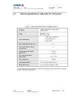
Page 7: ...s rack Depth 720 mm Weight Mainframe 24 kg Mod A1532 3 2 kg Power requirements Voltage range 100 230 Vac Frequency 50 60 Hz Power 3400 W Max number of boards per crate 16 Max number of power supply un...

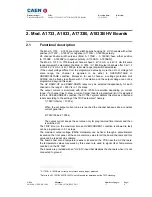
Page 8: ...for each channel in the range 1 500 V s in 1 V s steps The output current is monitored with 20 nA 200 nA resolution depending on current range if a channel tries to draw a current larger than its pro...

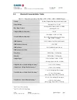
Page 9: ...n current range Mod A 1833 A 1833B VMAX hardware 0 4 kV common for all the board channels VMAX hardware accuracy 2 of FSR VMAX software 0 4 kV settable for each channel VMAX software resolution 1 V Ra...

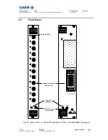
Page 10: ...U T P U T S SCALER POSITIVE 12 CH Mod V560E Mod A 1833P HV EN input connector Channel output connector Channel LED SCALER Mod V560E Mod A1833BP 28 CH HV EN MAXV GND GND GND GND GND NC NC NC NC NC 6 N...

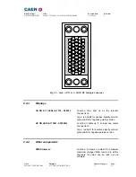
Page 11: ...733 A 1833 Mechanical specifications HV coaxial connectors Radiall SHVR317580 type Electrical specifications high voltage output according to specifications given in Table 2 1 p 9 CH 0 27 A 1733B A 18...

Page 12: ...r positive polarity version yellow LEDs for negative polarity version HV ON LED A 1733B A1833B Function it lights up if at least one output channel is on Type red LED for positive polarity version yel...

Page 13: ...ct only as specified Only qualified personnel should perform service procedures Avoid Electric Overload To avoid electric shock or fire hazard do not apply a voltage to a load that is outside the rang...

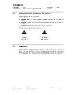
Page 14: ...tes an injury hazard not immediately accessible as you read the marking CAUTION indicates a hazard to property including the product The following symbols may appear on the product DANGER ATTENTION Hi...

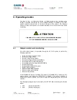
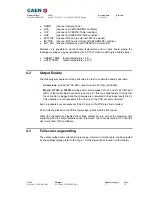
Page 15: ...t control and monitoring For each output channel it is possible through the SY 1527 system to perform the following operations Assign to channel a symbolic name Set output voltage VSET Set max output...

Page 16: ...ormed in order to enable the board s operation All versions provide the HV EN connector with a 50 Ohm termination Mod A 1733B A 1833B provide short circuit between Pin 51 and Pin 52 IINT and IEXT of t...

Page 17: ...ip Switch side view T A B C 4 3 2 1 A B Dip Switch T A B C 4 3 2 1 Channels Channels Channels Channels Channels Channels Channels Fig 4 1 A Mod A1733 A 1833 side view B Mod A1733B A 1833B top view In...

Reviews: