M a n u a l
OPTOSPLIT II
BYPASS
This guide details initial set up and installation of your OptoSplit II Bypass (BP) image splitter. Each unit is serial numbered,
calibrated and QC’d prior to delivery, therefore minimal setup is required providing you are familiar with the key controls.
For the purpose of this manual, all words in
bold blue
refer to parts labelled in diagrams throughout this document.
A supplementary Troubleshooting Guide is also available to address frequently asked questions during OptoSplit operation.
Please do not hesitate to contact us if you have any questions or issues during installation or operation
(
tech@cairn-research.co.uk
)
.
1) Mounting to your microscope
It is best practice to firstly ensure you have optimised your microscope light source in the absence of the
OptoSplit, with the camera mounted directly on the c-mount. Many technical queries are raised relating to
uneven illumination, which is often not introduced by the image splitter. Once both your transmitted and
fluorescent light source have been correctly aligned and focussed, the OptoSplit can be mounted on a 1x
c-mount; for deviations from this, please contact us for advice.
1.1) Correct camera orientation
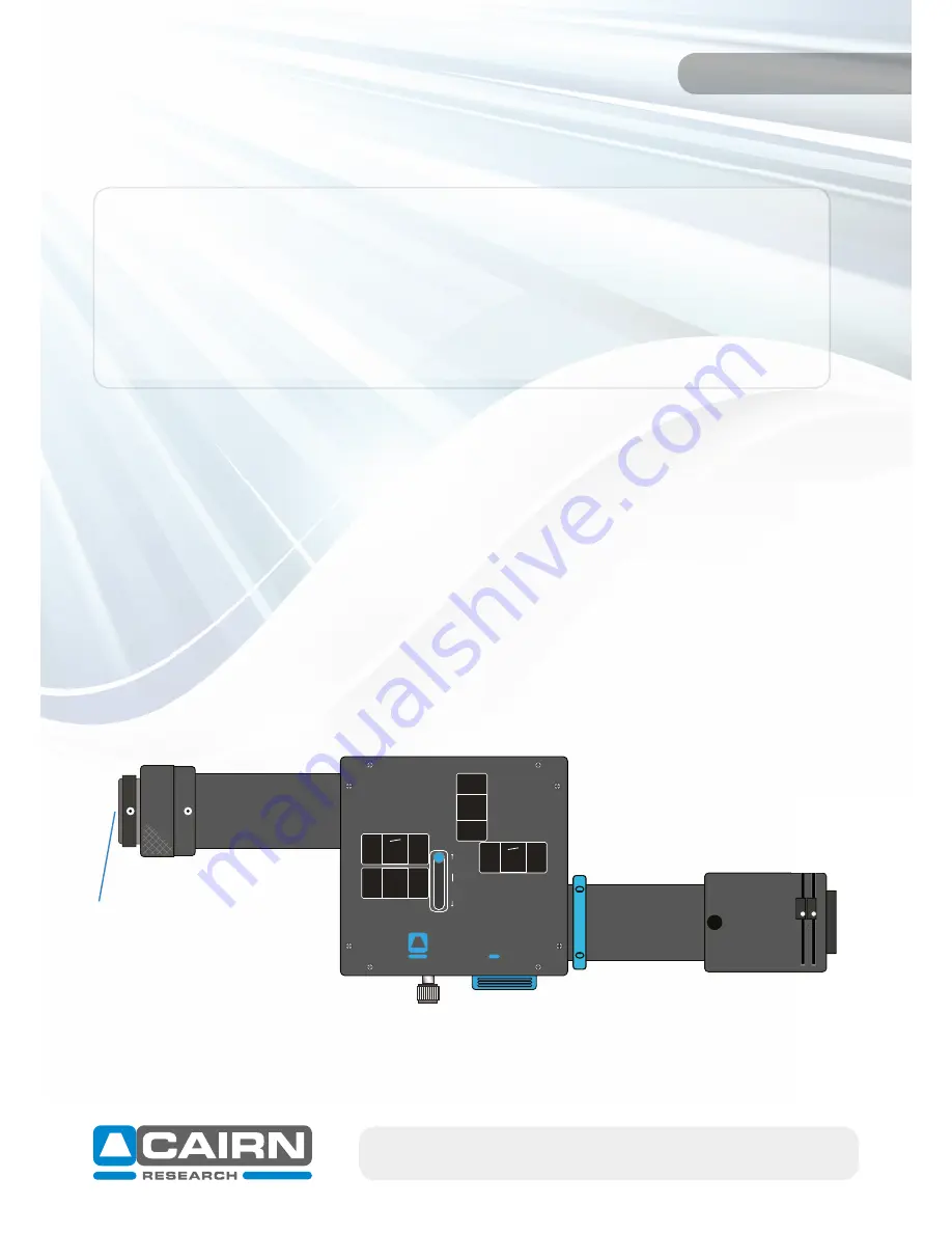
The OptoSplit
output port
connects to your camera c-mount via a
camera mounting thread
. The silver
knurled section on the output port can be rotated to secure the camera, whilst also ensuring any cables
connected do not get tangled.
The OptoSplit
input port
then connects to your microscope c-mount.
email: sales@cairn-research.co.uk tech@cairn-research.co.uk
+44(0)1795 590140 www.cairn-research.co.uk
For correct alignment of the two emission channels, the orientation of the camera once attached to the
OptoSplit II BP unit is important. Always ensure the top of your camera lies parallel with the top of the
OptoSplit. If fitting onto an upright microscope, this camera orientation remains the same.
BY
PASS
SPLIT
OPTOSPLIT
cairn-research.co.uk
Bypass
Input port
Camera mounting thread
Output port


