background image

CAL-ROYAL PRODUCTS Inc.

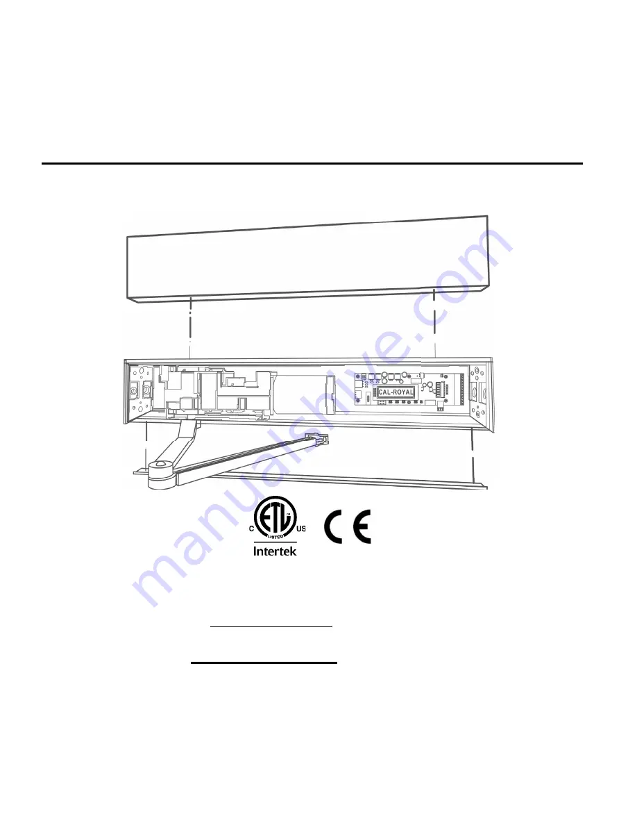
AUTOMATIC LOW ENERGY SWING DOOR OPERATOR

Operations & Installation Manual 

These original installation instructions detailed within are solely for 

These original installation instructions detailed within are solely for 

professional Installers and not intended to be handed over to the end user. 

professional Installers and not intended to be handed over to the end user. 

CAL-ROYAL PRODUCTS Inc.

6605 Flotilla Street, City of Commerce, CA 90040 USA 

Tel.# (323) 888-6601, FAX# (323) 888-6699 

WEB SITE: CAL-ROYAL.COM

Email: sales@cal-royal.com

Ver. October 31, 2020

Summary of Contents for 8600

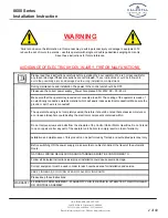
Page 1: ...nstallation instructions detailed within are solely for professional Installers and not intended to be handed over to the end user professional Installers and not intended to be handed over to the end...

Page 2: ...y the electronic components contained within Do not remove screws and bolts from the structure of the Control Unit or Motor Gear Box Do not intend to open repair or alter any part of the operator unit...

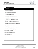
Page 3: ...com 1 0 PRODUCT SUMMARY 2 0 TECHNICAL SPECIFICATIONS 3 0 RECEIVING INSPECTION 4 0 PRE INSTALLATION INFO 5 0 INSTALLATION 6 0 ARM S INSTALLATION DOOR LEARNING CYCLE START UP 7 0 ELECTRONICS CONTROLLER...

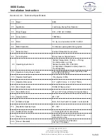
Page 4: ...n properly installed and programmed this product complies with ANSI BHMA A156 19 Standard for Power Assist and Low Energy Power Operated Swinging Doors It is the responsibility of the installer and or...

Page 5: ...ion or icing Ambient humidity 30 to 85 RH no hazardous materials must be present in the atmosphere 10 0 Operation During Power Failure Low manual resistance when opened by hand Door closing by spring...

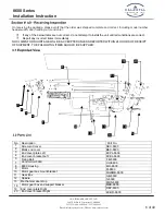
Page 6: ...SUPPLIED No Description Part No 1 Screw end cover 2 Blank end cover 3 End cover plate Left 4 End cover bracket Left 5 Fixing Bolt 7 Control Unit 8600 8 8600 Housing 1 3 2 4 7 8 16 5 9 11 10 12 13 19 2...

Page 7: ...ening and closing cycle before beginning of installation Incorrectly installed or improperly adjusted door operators can cause property damage or personal injury A dimensions are given in inches milli...

Page 8: ...Bits Level Tape Measure Wire Stripper Screwdrivers Flat Philip 5 16 Hex Nut Additional Fasteners Depending Surface Shims Hand Saw Power Saw for 14 x 2 3 4 70mm long sheet metal screws for wood for 12...

Page 9: ...struction 9 of 40 CAL ROYAL PRODUCTS INC 6605 Flotilla St Commerce CA 90040 Tel 323 888 6601 Fax 323 888 6699 Email sales cal royal com Website www calroyal com Operator a 1 6 Battery Back up Connecti...

Page 10: ...6699 Email sales cal royal com Website www calroyal com Arm that the operator is the correct orientation Left Push Right Push Left Pull or Right Pull 5 5 PULL Arm If the operator label is facing Down...

Page 11: ...ww calroyal com 5 5 Operator Installation Remove the cover from the assembly by gently pulling the cover down with minimal effort Carefully s Step 2 Remove the motor gearbox and control board from the...

Page 12: ...ply i nto the header at the same time as t he header assembly is positioned Step 4 Fixing Operator in Place Be sure t here i s proper support in the wall to secure t he header at the vertical jambs an...

Page 13: ...e the header back plate is in place install the motor gearbox and control board to the header back plate Slide the nuts supplied with the operator to hold the motor gear box and control board along th...

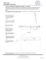
Page 14: ...drawings below Notes Base rail to be mounted flush with the bottom of the door frame A solid spacer material or filler may be required to compensate for any gap between the back of base rail and wall...

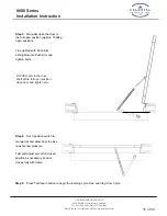
Page 15: ...n Approx 100deg open position Line up Rod with Push Arm sliding Rod into Push Arm and tighten bolts Step 4 Set 3 position switch to manual 0 and allow door to close under spring pressure Test and adju...

Page 16: ...he door to close under spring power Mark the closed position where the roller touches the door 4 Position slide track horizontally within 1st and 2nd mark then fix it to the door Slide the roller alon...

Page 17: ...Installation Instruction 17 of 40 CAL ROYAL PRODUCTS INC 6605 Flotilla St Commerce CA 90040 Tel 323 888 6601 Fax 323 888 6699 Email sales cal royal com Website www calroyal com THIS PAGE LEFT INTENTI...

Page 18: ...888 6699 Email sales cal royal com Website www calroyal com yc ycle le Start u Start up p TEST LEARN button is currently used for two functions a TEST an b LEARN a Note The built in mechanical doorst...

Page 19: ...Safety Speed Hold Crawl This setting is door speed when Safety 2 is active during the opening cycle Use the UP and DOWN buttons to select either Hold or Crawl speed 8 4 Closing Speed 01 15 This settin...

Page 20: ...ficient for most applications 8 12 Latch Position 2 30 This setting will adjust the door Latch position during the Closing cycle Use the UP and DOWN buttons to set the starting point for the Latch pos...

Page 21: ...ng is used for Access Control options including Electric Strikes Locking devices This requires a Wet Input connection to open A Wet Input will activate the Strike Lock and open the door simultaneously...

Page 22: ...he Strike Lock has been released Caution set the electric Lock Delay to a minimum of 0 2 seconds 8 28 Reverse on Obstruction Yes No This setting will Enable or Disable the Re activation feature If Ena...

Page 23: ...Fax 323 888 6699 Email sales cal royal com Website www calroyal com 8 31 Software Version MSW01 vX XX This menu will display the Software version in the Control unit where X equals a numeric value Th...

Page 24: ...est 15sec fastest 5 5 LATCH SPEED Door speed at final section of closing 1 to 5 1sec slowest 5sec fastest 1 6 CURRENT LIMIT Obstruction detection 1 to 20 1sec more sensitive 20sec less sensitive 10 7...

Page 25: ...ted ON Normal 20 IN1 WET INPUT 2 options NC Normally Closed NO Normally Open NO 21 OVERLAP 2 options Y Yes N No No 22 FACTORY RESET 2 options Y Yes N No No 23 LIGHT ON TIME Time backlight remains on 3...

Page 26: ...o open by hand and will fully close with spring power This function does not switch off the power however motion sensors push plates are still active but are ignored Automatic Motion sensors push plat...

Page 27: ...of 40 CAL ROYAL PRODUCTS INC 6605 Flotilla St Commerce CA 90040 Tel 323 888 6601 Fax 323 888 6699 Email sales cal royal com Website www calroyal com 9 4 Safety 1 24v 12v GND NC NO COM CAL ROYAL 9 4 S...

Page 28: ...ction 28 of 40 CAL ROYAL PRODUCTS INC 6605 Flotilla St Commerce CA 90040 Tel 323 888 6601 Fax 323 888 6699 Email sales cal royal com Website www calroyal com 9 8 Electromagnetic Lock CAL ROYAL CAL ROY...

Page 29: ...Installation Instruction 29 of 40 CAL ROYAL PRODUCTS INC 6605 Flotilla St Commerce CA 90040 Tel 323 888 6601 Fax 323 888 6699 Email sales cal royal com Website www calroyal com THIS PAGE LEFT INTENTI...

Page 30: ...888 6601 Fax 323 888 6699 Email sales cal royal com Website www calroyal com Invert the entire operator assembly 180 degrees Remove d rive shaft spindle f rom motor gear box assembly See changing posi...

Page 31: ...m Website www calroyal com Step 4 Detach wire connections from operator to control board Step 5 Remove control assembly from the base and rotate 180 degrees Step 6 Replace control and socket screws De...

Page 32: ...mmerce CA 90040 Tel 323 888 6601 Fax 323 888 6699 Email sales cal royal com Website www calroyal com Step 7 Connect wire harness Step 8 Insert spline shaft on the operator depended on push or pull app...

Page 33: ...Installation Instruction 33 of 40 CAL ROYAL PRODUCTS INC 6605 Flotilla St Commerce CA 90040 Tel 323 888 6601 Fax 323 888 6699 Email sales cal royal com Website www calroyal com THIS PAGE LEFT INTENTI...

Page 34: ...00 Series Installation Instruction 34 of 40 CAL ROYAL PRODUCTS INC 6605 Flotilla St Commerce CA 90040 Tel 323 888 6601 Fax 323 888 6699 Email sales cal royal com Website www calroyal com E Section 11...

Page 35: ...s Installation Instruction 35 of 40 CAL ROYAL PRODUCTS INC 6605 Flotilla St Commerce CA 90040 Tel 323 888 6601 Fax 323 888 6699 Email sales cal royal com Website www calroyal com Section 2 COM NO NC G...

Page 36: ...lation Instruction 36 of 40 CAL ROYAL PRODUCTS INC 6605 Flotilla St Commerce CA 90040 Tel 323 888 6601 Fax 323 888 6699 Email sales cal royal com Website www calroyal com Output 24VDC 1200Ma Max Outpu...

Page 37: ...cal royal com Website www calroyal com J6 Connector Description Motor encoder PIN Definition J6 1 Output 5V DC J6 2 Input Encoder Signal B J6 3 Input Encoder Signal A J6 4 COM Ground J7 Connector Des...

Page 38: ...YAL PRODUCTS INC 6605 Flotilla St Commerce CA 90040 Tel 323 888 6601 Fax 323 888 6699 Email sales cal royal com Website www calroyal com always follow the safety sensor device manufacturer s detailed...

Page 39: ...further guidelines on switch requirements Activation switches shall be at minimum height of 34 and maximum height of 48 from finished floors Individual who uses wheelchair need a minimum of 48 clearan...

Page 40: ...Installation Instruction 40 of 40 CAL ROYAL PRODUCTS INC 6605 Flotilla St Commerce CA 90040 Tel 323 888 6601 Fax 323 888 6699 Email sales cal royal com Website www calroyal com THIS PAGE LEFT INTENTI...

Reviews: