background image

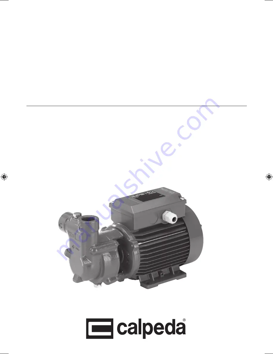
Pompe autoadescanti ad anello liquido

Self-Priming Liquid Ring Pumps

Selbstansaugende Flüssigkeitsringpumpen

Pompes autoamorçantes à anneau liquide

Bombas autoaspirantes de anillo liquido

Självevakuerande vätskeringpumpar

Zelfaanzuigende vloeistofring pompen

Αυτομάτου αναρροφήσεως υγρού δακτυλίου αντλίες

C‡ÏÓÁ‡ÎË‚‡˛˘ËÂÒfl ‚Ó‰ÓÍÓθˆÂ‚˚Â

液环自吸泵

CA

ISTRUZIONI ORIGINALI PER L’USO


Pagina  

Italiano

OPERATING INSTRUCTIONS


Page  

English

BETRIEBSANLEITUNG


Seite  

14 

Deutsch

INSTRUCTIONS POUR L’UTILISATION


Page  

20 

Français

INSTRUCCIONES DE USO


Página   26 

Español

DRIFT/INSTALLATIONSANVISNINGAR


Sidan  

32 

Svenska

BEDIENINGSVOORSCHRIFT


Pagina   38  Nederlands

ΟΔΗΓΙΕΣ ΧΕΙΡΙΣΜΟΥ


Σελίδα  44 

Ελληνικά

àÌÒÚÛ͈ËË ÔÓ ˝ÍÒÔÎÛ‡Ú‡ˆËË


ëÚ. 

50 

êÛÒÒÍËÈ

安装使用手册


页码 

56 

中文

CA  Rev4.indd   1

04/07/18   15:26

Summary of Contents for CA Series

Page 1: ...j lvevakuerande v tskeringpumpar Zelfaanzuigende vloeistofring pompen C fl CA ISTRUZIONI ORIGINALI PER L USO Pagina 2 Italiano OPERATING INSTRUCTIONS Page 8 English BETRIEBSANLEITUNG Seite 14 Deutsch...

Page 2: ...lare capitolo 6 5 1 1 Simbologia utilizzata Per migliorare la comprensione si utilizzano i simboli pittogrammi sotto riportati con i relativi significati Informazioni ed avvertenze che devono essere r...

Page 3: ...identificazione presente sull involucro esterno della pompa 1 Tipo 2 Portata 3 Prevalenza 4 Potenza nominale 5 Tensione di alim 6 Corrente 7 Eventuali note 8 Frequenza 9 Tipo di servizio 10 Classe iso...

Page 4: ...otenzialmente esplosiva 6 3 Disimballaggio i Verificare che l apparecchio non sia stato danneggiato durante il trasporto Il materiale d imballo una volta disimballata la macchina dovr essere eliminato...

Page 5: ...al ridotto gioco assiale della girante in questo tipo di pompe la girante ruoter liberamente dopo un breve periodo di funzionamento All avviamento con alimentazione trifase verificare che il senso di...

Page 6: ...tenzione ordinaria OFF Prima di ogni intervento di manutenzione togliere l alimentazione elettrica e assicurarsi che la pompa non rischi di essere messa sotto tensione per inavvertenza Quando la pompa...

Page 7: ...a tenuta e sigillare in modo pi efficace la connessione b Pulire o sostituire la valvola di fondo e impiegare un tubo di aspirazione idoneo all applicazione c Pulire il filtro se necessario sostituir...

Page 8: ...e installed chapter 6 5 1 1 Symbols To improve the understanding of the manual below are indicated the symbols used with the related meaning Information and warnings that must be observed otherwise th...

Page 9: ...late that is on the external case of the pump 1 Pump type 2 Delivery 3 Head 4 Rated power 5 Tension nominale 6 Nom motor current 7 Notes 8 Fr quence 9 Operation Duty 10 Insulation class 11 Weight 12 P...

Page 10: ...here 6 3 Unpacking i Inspect the device in order to check any damages which may have occurred during transportation Package material once removed must be discarded recycled according to local laws of...

Page 11: ...tation is as shown by the arrows on the lantern bracket Otherwise disconnect electrical power and reverse the connections of two phases Check that the pump works within its field of perfor mance and t...

Page 12: ...ve the pump and turn it upside down After a long idle period before restarting the unit check that the impeller is not jammed because of incrustations settling solids deposit formation or other causes...

Page 13: ...ry replace it See point 2a also 4 Insufficient flow 4a Pipes and accessories with diameter too small causing excessive loss of head 4b Presence of deposits or solid bodies in the internal passages of...

Page 14: ...Den maximale zul ssigen Geh useenddruck Kapitel 3 1 Typ und Querschnitt des Anschlusskabels Kapitel 6 5 Den Typ der zu installierenden elektrischenAbsicherung Kapitel 6 5 1 1 Verwendete Symbole Zum b...

Page 15: ...s verboten Die Fehlanwendung des Produktes verringert seine Sicherheits und Effizienzmerkmale Calpeda haftet nicht f r M ngel oder Unf lle welche aus der Nichtbeachtung der oben beschriebenen Verbote...

Page 16: ...am Aufstellungsort Der Aufstellungsort ist entsprechend und mit Bezug auf dessen Besonderheiten vorzubereiten damit die Installation reibungslos erfolgen kann elektrische Anschl sse usw Die Umgebung...

Page 17: ...n vom kleinem Axialspiel vom Laufrad in diesem Pumpenbauart verursacht sein das Laufrad wird sich nach dem Einlaufen lockern Bei demAnlauf mit Dreiphasen Drehstrommotoren die Drehrichtung pr fen die d...

Page 18: ...t ist das Ger t vom Stromnetz zu trennen und sicherzustellen dass die Pumpe nicht unerw nscht wieder unter Spannung gesetzt werden darf Wird die Pumpe nicht eingesetzt so mu sie bei Frostgefahr vollst...

Page 19: ...ch Punkt 2a 4 Zu geringe F rdermenge 4a Verrohrung und Armaturen mit zu kleiner Nennweite verusachen zu gro e Verluste 4b Feststoffe oder Ablagerungen im Laufrad oder Pumpengeh use 4c Laufrad defekt 4...

Page 20: ...alimentation chapitre 6 5 Le type de protection lectrique installer chapitre 6 5 1 1 Pictogrammes utilis s Pour une compr hension plus facile les symboles pictogrammes ci dessous sont utilis s dans l...

Page 21: ...tenue responsable des pannes ou des accidents dus l inobservation des interdictions pr sent es ci dessus 2 3 Marquage Ci dessous voici une copie d une plaquette d identification situ e sur le corps ex...

Page 22: ...ectrique etc L endroit o installer l appareil doit avoir les qualit s requises au paragraphe 3 2 Interdiction absolue d installer et de mettre en service la machine dans des lieux avec une atmosph re...

Page 23: ...nterne de raccordement dans le cas contraire d brancher l alimentation l ctrique et inverser les connexions des deux phases Contr ler que la pompe travaille dans son champ de performance et que le cou...

Page 24: ...compl tement s il existe un danger de gel Pour vidanger compl tement les pompes d monter la pompe et la renverser Apr s une longue arr t avant de remettre en marche l ensemble contr ler que la roue n...

Page 25: ...er aussi le paragraphe 2a 4 D bit insuffisant 4a Tuyaux et accessoires avec un diam tre trop petit entra nant des pertes de charge 4b Pr sence de d p ts et de corps trangers dans l int rieur du passag...

Page 26: ...rensi n se utilizan los s mbolos pictogramas a continuaci n con sus significados Informaci n y advertencias que deben respetarse si no causan da os al aparato o ponen en peligro la seguridad del perso...

Page 27: ...ci n se muestra una copia de la tarjeta de identificaci n presente en el exterior de la bomba 1 Tipo de bomba 2 Capacidad 3 Altura 4 Potencia nominal 5 Tensi n nominal 6 Corriente nom 7 Notas 8 Frecue...

Page 28: ...otencialmente explosiva 6 3 Desembalaje i Comprobar que el dispositivo no haya sufrido da os durante el transporte El material de embalaje una vez desembalada la m quina debe eliminarse y o utilizarse...

Page 29: ...ento motor bomba En caso contrario desconectar la alimentaci n el ctrica e invertir entre ellos el conexionado de dos fases Controlar que la bomba trabaja en su campo de prestaciones y que no venga su...

Page 30: ...alimentaci n y aseg rese de que la bomba no pueda recibir tensi n por error Si la bomba permanece inactiva por largo periodo de tiempo o si existe peligro de heladas esta debe de ser vaciada completa...

Page 31: ...ci n c Limpiar el filtro si es necesario sustituirlo Ver tambi n el punto 2a 4 Caudal insuficiente a Tuber a y accesorios con di metro demasiado peque o que provocan excesivas perdidas de carga b Pres...

Page 32: ...el 6 5 1 1 Symboler som anv nds F r att underl tta f rst elsen anv nds de symboler piktogram som indikeras nedan med respektive betydelser Information och varningstexter m ste iakttas annars kan det l...

Page 33: ...mmelse att iaktta ovan n mnda f rbud 2 3 M rkning Nedan f ljer en kopia av m rkskylten som r placerad p pumpens yttre h lje 1 Pump typ 2 Fl de 3 Tryck 4 Avgiven effekt 5 Driftsp nning 6 Str mf rbrukni...

Page 34: ...krav och m tt p installationsplatsen Kunden ska f rbereda installationsplatsen p l mpligt s tt f r en korrekt installation och i enlighet med konstruktionskraven elanslutningar osv Den omgivning i vi...

Page 35: ...fasinstallation kotrollera att rotationsrikningen st mmer med pilen p mellandelen om inte bryt all elstr m och skifta tv av elfaserna till elmotorn Kontrollera att pumpen arbetar inom sin kurva och at...

Page 36: ...A S p A 8 1 L pande underh ll OFF Fr nkoppla elf rs rjningen och s kerst ll att pumpen inte riskerar att oavsiktligen sp nningsf ras innan n gon underh lls tg rd utf rs Om pumpen ej anv nds m ste den...

Page 37: ...ameter medf r stora f rluster 4b N rvaro av f roreningar i pumphjulet 4c Pumphjul igensatt 4d Slitet pumphus eller pumphjul 4e verskriden viskositet p v tskan om annat n vatten 4f Felaktig rotationsri...

Page 38: ...5 1 1 Gebruikte symbolen Voor een beter begrip zijn de onderstaande symbolen pictogrammen met hun betekenis gebruikt Informatie en waarschuwingen die in acht moeten worden genomen zo niet dan veroorz...

Page 39: ...het identificatieplaatje dat zich op de buitenkant van de pomp bevindt 1 Pomptype 2 Capaciteit 3 Opvoerhoogte 4 Motorvermogen 5 Voeding voltage 6 Nom motorstroom 7 Opmerkingen 8 Frequentie 9 Operation...

Page 40: ...n werking te stellen in een ruimte met een potentieel ontploffingsgevaar 6 3 Uitpakken i Controleer dat het apparaat tijdens het transport niet beschadigd is Het verpakkingsmateriaal moet nadat de mac...

Page 41: ...en vermogen voldoet aan de specificaties op het typeplaatje Indien de stroomsterkte te hoog is dienen de klep of kleppen in de persleiding zodanig versteld te worden dat e e a weer conform de markerin...

Page 42: ...ren moet de elektrische stroom worden uitgeschakeld en gecontroleerd worden dat de pomp niet onverwacht onder spanning kan komen te staan In geval van verwachte stilstand voor langere periode of vorst...

Page 43: ...quaat 3b Maak de voetklep schoon of vervang die gebruik de juiste zuigleiding voor de toepassing 3c Maak het filter schoon of vervang het filter zie punt 2b 4 Onvoldoen capaciteit 4a Te kleine leiding...

Page 44: ...S p A 1 Calpeda SpA 2 3 8 3 1 6 5 6 5 1 1 i E E OFF ON 1 2 Calpeda S p A Via Roggia di Mezzo 39 36050 Montorso Vicentino Vicenza Italia www calpeda it 1 44 2 45 3 45 4 45 5 46 6 46 7 47 8 48 9 48 10...

Page 45: ...Italy XXXXXXX Q min max X X m3 h XXXXXXX H max min X X m IP XX n XXXX min 220 380Y V3 50Hz cos X X X A XXXXXXXX S1 l cl X X kg X kW XHp S F 1 2 3 4 5 6 7 8 9 10 16 15 14 13 12 11 Montorso VI Italy IT...

Page 46: ...GR 46 64 CA Rev4 4 2 4 3 4 4 4 5 5 5 1 25 kg 6 6 1 6 2 3 2 6 3 i 6 4 6 4 1 6 4 2 6 4 3 15 m 6 5 OFF L...

Page 47: ...GR CA Rev4 47 64 07 RN F 13 1 TAB 1 30mA 3 mm D CAM 220 240V 7 7 1 7 2 OFF 1m 5 7 3 i 5 7 3 1 60 C 80 C 7 4 OFF ON 6 5...

Page 48: ...CA 8 2 8 3 OFF 9 OFF 2012 19 EU WEEE 10 10 1 CALPEDA S p A 11 14 00 14 04 14 12 14 20 14 24 26 00 Diffuser 26 04 28 00 28 20 32 00 36 00 36 50 46 00 73 00 76 00 76 04 76 54 78 00 81 00 82 00 82 04 88...

Page 49: ...12 OFF 1 1a 1b 1c 1d 1e 1f 1a 1b 1c 1d a c 1e 1f 2 2a 2b 2c 2a 2b 2c 3 3a 3b 3c 3a 3b 3c 2b 4 4a 4b 4c 4d 4e 4f 4g 4h 4a 4b 4c 4d 4e 4f 4g 4h 5 5a 5b 5c 5d 5e 5f 5a 5b 5c 5d 5e 5f 6 6a 6b 6c 6d 6a 6b...

Page 50: ...S P A 1 Calpeda S p A 2 3 CE 8 3 1 6 5 6 5 1 1 i OFF ON 1 2 Calpeda S p A Via Roggia di Mezzo 39 36050 Montorso Vicentino Vicenza Italia www calpeda it 1 50 2 51 3 51 4 51 5 52 6 6 52 7 53 8 54 9 54 1...

Page 51: ...5 16 Made in Italy XXXXXXX Q min max X X m3 h XXXXXXX H max min X X m IP XX n XXXX min 220 380Y V3 50Hz cos X X X A XXXXXXXX S1 l cl X X kg X kW XHp S F 1 2 3 4 5 6 7 8 9 10 16 15 14 13 12 11 Montorso...

Page 52: ...RU C 52 64 CA Rev4 4 2 4 3 4 4 4 5 5 5 1 25 6 6 6 1 6 1 6 2 3 2 6 3 i 6 4 6 4 1 6 4 2 6 4 3 15 6 5 OFF...

Page 53: ...RU CA Rev4 C 53 64 07 RN F 13 1 TAB 1 I N 30 mA 3 D CAM 50 220 240 7 7 1 7 2 OFF 1 5 7 3 i 5 7 3 1 5 60 80...

Page 54: ...da S p A 8 1 OFF A 8 2 8 3 OFF 9 OFF 2012 19 EU WEEE 10 10 1 Calpeda S p A 11 Nr 14 00 14 12 14 20 14 24 14 42 26 00 26 04 28 00 28 20 32 00 36 00 36 50 46 00 73 00 76 00 76 04 76 54 78 00 81 00 82 00...

Page 55: ...RU CA Rev4 C 55 64 12 OFF 1 2 a a 3 a a 2 a 4 a a 5 a a 4 6 a 5 6 6 6...

Page 56: ...1 CALPEDA S P A 2 3 CE 8 3 1 6 5 6 5 1 1 i OFF ON 1 2 CALPEDA S P A Via Roggia di Mezzo 39 36050 Montorso Vicentino Vicenza Italia www calpeda it 1 3 i 1 4 i 1 56 2 57 3 57 4 57 5 58 6 58 7 59 8 59 9...

Page 57: ...XXX Q min max X X m3 h XXXXXXX H max min X X m IP XX n XXXX min 220 380Y V3 50Hz cos X X X A XXXXXXXX S1 l cl X X kg X kW XHp S F 1 2 3 4 5 6 7 8 9 10 16 15 14 13 12 11 Montorso VI Italy IT 0014263024...

Page 58: ...58 64 CA Rev4 4 5 5 5 1 25 6 6 1 6 2 3 2 6 3 i 6 4 6 4 1 6 4 2 6 4 3 _ 15m 6 5 OFF H07RN F 13 1 30 3mm D CAM 220 240V 50Hz...

Page 59: ...CA Rev4 59 64 7 7 1 7 2 OFF 1m 5 7 3 i 5 7 3 1 60 80 7 4 ON 6 5 8 i i CALPEDA CALPEDA S P A...

Page 60: ...8 3 OFF 9 OFF WEEE 2012 19 EU 10 10 1 CALPEDA S P A 11 14 00 14 04 14 12 14 20 O 14 24 26 00 26 04 28 00 28 20 32 00 36 00 36 50 46 00 73 00 76 00 76 04 76 54 78 00 81 00 82 00 82 04 88 00 90 00 92 00...

Page 61: ...1b 1c 1d 1e 1f 1a 1b 1c 1d a c 1e 2 1f 2 2a 2b 2c 2a 2b 2c 3 3a 3b 3c 3a 3b 3c 2a 4 4a 4b 4c 4d 4e 4f 4g 4h 4a 4b 4c 4d 4e 4f 4g 4h 5 5a 5b 5c 5d 5e 5f 5g 5a 5b 5c 5d 5e 4g 5f 5g 6 6a 6b 6c 6d 6a 6b...

Page 62: ...4 04 14 00 36 00 36 50 14 20 14 12 26 00 26 04 28 20 76 50 70 18 70 00 76 54 76 04 98 00 94 00 94 02 98 04 90 00 46 00 73 00 78 00 81 00 82 04 92 00 82 00 90 04 88 00 32 00 14 24 28 00 36 50 36 00 14...

Page 63: ...CALPEDA S p A erkl rer hermed at vore pumper CA CAM B CA B CAM pumpe type og serie nummer vist p typeskiltet er fremstillet i overensstemmelse med bestemmelserne i Direktiv 2006 42 EC 2009 125 EC 2014...

Page 64: ...Calpeda s p a Via Roggia di Mezzo 39 36050 Montorso Vicentino Vicenza Italia Tel 39 0444 476476 Fax 39 0444 476477 E mail info calpeda it www calpeda com...

Reviews: