background image

calrec.com

Omega

 InstallatIOn manual

Digital Broadcast Production Console with Bluefin HDSP

Putting Sound in the Picture

Summary of Contents for OMEGA

Page 1: ...calrec com Omega Installation Manual Digital Broadcast Production Console with Bluefin HDSP Putting Sound in the Picture...

Page 2: ...national usage Calrec Audio Ltd reserve the right to change specifications without notice E O E The established policy of Calrec Audio Ltd is to seek improvements to the design specifications and manu...

Page 3: ...lby DP570 DP564 setup 31 Talkback Mic Desk Headphones 32 Serial Interface 35 MADI 36 Hydra Audio Networking 37 Hydra Technology 38 Typical Hydra Network Example 39 Console Hardware 40 Gigabit Switch 4...

Page 4: ...upon request should you require assistance This applies particularly to digital products due to the types of devices and very small geometries used in their fabrication analog parts can however still...

Page 5: ...or cleaning the front panels of the equipment we recommend anti static screen cleaner sprayed onto a soft cloth to dampen it only Health and Safety Explanation of Warning Symbols The triangular warnin...

Page 6: ...g machine all messages are dealt with promptly on the next working day Alternatively a message can be sent to them by email Product Warranty A full list of our conditions warranties relating to Goods...

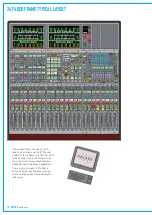
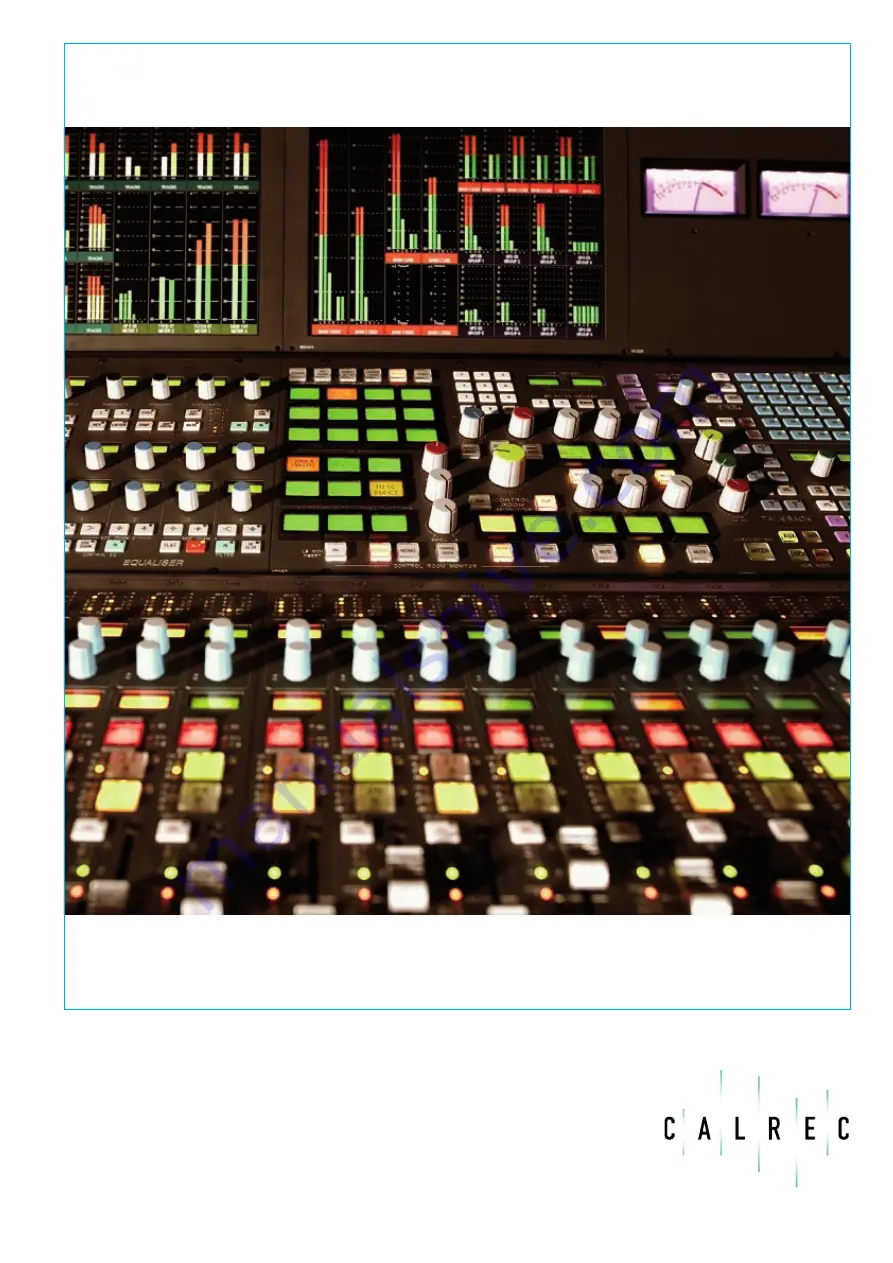
Page 7: ...calrec com OMEGA Putting Sound in the Picture Overview...

Page 8: ...or power supplies control cards and DSP cards Hot plugging of every card and module Hot plugged cards initialise upon insertion System Overview INPUT MATRIX A CHANNELS B CHANNELS UP TO 48 STEREO 64 MO...

Page 9: ...3 Wide Area Interfaces Up to 4 AES cards each providing 32 stereo inputs and 32 stereo outputs Up to 3 Mic Line input cards each providing 16 stereo inputs AES card slots can be occupied by Wide Area...

Page 10: ...l Considerations The whole system must be powered from the same phase of the AC power supply All modules cards and cables are designed to permit hot plugging Touch Screen If the console is installed i...

Page 11: ...channel direct output can only be connected to the L R of a pair of ports A mono channel input or direct output can be connected to any of The L or R of a pair of ports or any mono port Mono ports sh...

Page 12: ...0dBFS 1kHz Better than 0 3 Frequency response 20Hz to 20kHz 0 25dB Crosstalk 20Hz to 20kHz 86dB Delay 0 3ms ANALOG OUTPUTS Digital analog conversion 24 Bit Output balance Electronically Balanced 20Hz...

Page 13: ...calrec com OMEGA Putting Sound in the Picture Frame Options and Dimensions...

Page 14: ...thin a frame only 784 mm 30 9 inches wide Due to the compact size the colour touch screen keyboard and trackball need to be housed separately There is also no space to fit either a surround spill or j...

Page 15: ...me houses up to 40 faders which allows up to 80 Channel Faders within a frame only 1290 mm 50 8 inches wide Fitting a surround spill and or joystick panel in the 40 fader frame reduces the frame capac...

Page 16: ...1796 mm 70 7 inches wide When joystick and or surround spill panels are fitted in the fader area the maximum number of faders is reduced to 48 However alternative short surround and spill panels can b...

Page 17: ...pth Front Elevation inches mm inches mm inches mm 24 Fader Frame 30 9 784 33 3 845 15 5 393 40 Fader Frame 50 8 1290 33 3 845 15 5 393 56 Fader Frame 70 7 1796 33 3 845 15 5 393 The end profile is the...

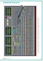
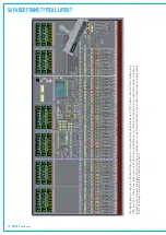
Page 18: ...18 OMEGA with Bluefin...

Page 19: ...calrec com OMEGA Putting Sound in the Picture Equipment Installation...

Page 20: ...s than 5 extra Processing Rack Unpopulated 7U 19 7 500 29 5 13 4 Processing Rack Populated 7U 19 7 500 42 3 19 2 PC 3U 23 7 600 27 12 2 400 Hydra Gigabit Interface Unit 1U 11 9 300 6 2 7 MADI Unit 1U...

Page 21: ...incorporates a baffle such that warm air is drawn out of the rack and out through the rear of the fan tray 2 slots for DSP Cards 2 slots for Processor Cards 3 slots for ADC Analog Input Cards 3 slots...

Page 22: ...power from each plug in unit is 600 W Hot Swapping The units can be hot swapped providing there is enough output power remaining to drive the load Each unit has a bargraph to indicate the output power...

Page 23: ...to the rear Fan Cooling The multi rail power supply unit is fan cooled but uses a very low noise fan drawing air from side to side through the PSU instead of in from the front to minimise noise Shoul...

Page 24: ...8V FASTLINK J2 METERDATA J40 RS232 J43 J42 OMEGA CONSOLE INTERFACE REAR OF CONSOLE 27 RJ45 8V 50F D TYPE 50F D TYPE 50F D TYPE 9MD TYPE POWER 8DV P POWER 8DV P D37F SP PF J58 PSUMON RESET 9MD TYPE 9MD...

Page 25: ...FAN FAIL INPUT 9M D TYPE J32 DSP RACK RESET OUTPUT FAN FAIL INPUT POWER 5DV S J8 24V DC OUTPUT 2 J9 AUXILIARY 24V O P 2 POWER 5DV S J7 24V DC OUTPUT 1 J3 AUXILIARY 24V O P 1 POWER 5DV S J11 24V DC OU...

Page 26: ...s provided to enable the PC to be connected to a Calrec Hydra Audio Network which is an option which can either be purchased with the console or in the future Software Supplied An OEM PC Operating Sys...

Page 27: ...After a software upgrade the main set of memories will be upgraded and checked by the engineer carrying out the upgrade A new backup should then be made of these memories C Omega Cust1 Meter This is t...

Page 28: ...to drives other than the one within the console PC Setting up SNMP reporting SNMP reporting must first be enabled by clicking in the Enable box within the Setup Application The two console network int...

Page 29: ...ication 5 24 V Darlington Specification 30 V 5 mA GPIO Connections Pins Circuit 1 18 5L 34 2 Opto 9 IN 19 35 Opto 10 IN 3 20 Opto 11 IN 36 4 Opto 12 IN 21 37 Opto 13 IN 5 22 Opto 14 IN 38 6 Opto 15 IN...

Page 30: ...9M D TYPE J31 ANALOG PSU 1 MON RACK FAN 24V ZH5527 PSU RACK POWER 3DV S POWER 3DV S POWER AC POWER AC POWER AC 8 change over relays are also available on the rear of the Bulk Power Supply and Distrib...

Page 31: ...olby DP570 DP564 setup On the Dolby unit label means press the button with the name label Power up the unit and wait for it to initialise setup down arrow until you see SYSTEM SETTINGS enter Unit name...

Page 32: ...USB 1 1 port primarily for connecting a flash memory device for loading and storing console settings Both panels contains the following talkback microphone circuitry Talkback microphone pre amplifier...

Page 33: ...HEADPHONE O P SW4 NORMAL REV MIC GAIN VR4 16V MIC PHANTOM SW9 OFF ON DIGITAL ANA TB MIC SW5 Headphone connections The headphone jack is located underneath the console on an interface plate next to th...

Page 34: ...2 J3 RJ45 8V DEBUG 2 J39 RJ45 8V RS422 1 J2 RJ45 8V DEBUG 1 9M D TYPE 1 J41 RS232 9M D TYPE 1 J40 RS232 9M D TYPE 1 J49 RS232 POWER 8DV J43 1 POWER 8DV J42 1 Microphone audio The output of the microph...

Page 35: ...g equipment to be connected to the system The Serial Port Settings screen is used to tell the system what information it should send and receive via the serial interface port by allocating a function...

Page 36: ...xial AND optical medium and receive over a coaxial OR optical medium A switch allows receiver selection MADI Front Rear There is no sample rate conversion available on MADI inputs or outputs therefore...

Page 37: ...calrec com OMEGA Putting Sound in the Picture Hydra Audio Networking...

Page 38: ...ors on the front of the unit s processor module As this is a copper interface when using fiber cabling Power Fault hp Procurve Switch 2824 Wide Area Bulk Card DSP Digital I O Rack Audio Control Data f...

Page 39: ...dios Equipment Hydra Audio Networ 04 10 0 C Western Title Project Issue date Drawn Calrec Audio Ltd Nutclough Mill Hebden Bridge West Yorkshire HX7 8EZ Tel 01422 842159 Fax 01422 84524 www calrec c en...

Page 40: ...rear of the unit The second Gigabit port on the unit is not used The unit runs at Gigabit speed all the time and may not be connected to switch ports that run at lower speeds The unit is powered from...

Page 41: ...ernally which has led to incompatibilities with our system It is for this reason that Calrec do not warrant our products for any Hydra network problem unless the HP ProCurve switches we recommend are...

Page 42: ...s with 1000BASE SX for distances up to 550 m and 1000BASE LX for distances up to 10 km are available All external connections to the units are hot pluggable If more than one media type is detected the...

Page 43: ...00 12 5 8 100 240V AC 0 38 0 20A RMS 50 60Hz VI5672 4 SDI in and through rear connectors 2U 19 483 12 300 13 9 6 3 100 240V AC 50 60Hz Calrec SDI boxes come in two dif ferent versions one for use with...

Page 44: ...SB USB 32 AES INPUTS 32 AES OUTPUTS Status LEDs The following indicative LEDs are visible from the front panel PSU OK green Fan Fail red Port 1 connected yellow Port 1 active green Port 2 connected ye...

Page 45: ...hole is located on the module front panels to help remove modules for service purposes The module slides in and out the unit on two runners at the top and bottom of the rack The rear interface connec...

Page 46: ...air is directed out of the rear of the rack To ensure proper cooling there must be a minimum clearance of two inches 50 mm from the fans and rear air outlets and also any walls or other surfaces Inter...

Page 47: ...et less the combined losses of connectors splices and fibre is still a positive number then the system will work Fibre cable construction When installing fibre cable it is important to use a type whic...

Page 48: ...optical interfaces Do not install any unauthorized modifications to the optical devices The following tools can be useful for optical maintenance Compressed air Clean Dry Air is essential to ensure t...

Page 49: ...Examine the surface of the fibre end under high intensity light using a direct magnifying inspection microscope or an indirect video inspection tool if available If streaks or contaminants still rema...

Page 50: ...tightening deforms the twisted pairs within the cable and can affect their performance The cable ties should only be tight enough to sufficiently support the cable bundle and not to deform the outer...

Page 51: ...calrec com OMEGA Putting Sound in the Picture Audio I O Interfaces...

Page 52: ...TOR 1 J62 J41 J63 J42 2 J47 J49 J48 J51 3 J57 J67 J58 J69 4 J74 J76 J75 J77 SCSI 36F J120 ADC3 1 8 SCSI 36F J121 ADC3 9 16 SCSI 36F J101 ADC2 1 8 SCSI 36F J103 ADC2 9 16 SCSI 36F J95 ADC1 1 8 SCSI 36F...

Page 53: ...16 SCSI 36F SCSI 36F J67 J49 AES2 IN 17 32 AES3 IN 17 32 SCSI 36F J41 AES1 IN 17 32 SCSI 36F J69 AES3 OUT 17 32 SCSI 36F J51 AES2 OUT 17 32 SCSI 36F J42 AES1 OUT 17 32 SCSI 36F J76 AES4 IN 17 32 SCSI...

Page 54: ...3 XLR NC3FV 1 2 3 XLR NC3FV 1 2 3 XLR NC3FV 1 2 3 XLR NC3FV 1 2 3 XLR NC3FV 1 2 3 XLR NC3FV 1 2 3 XLR NC3FV 1 2 3 XLR NC3FV 1 2 3 XLR NC3FV 1 2 3 XLR NC3FV 1 2 3 XLR NC3FV 1 2 3 XLR NC3FV 1 2 3 XLR NC...

Page 55: ...ectors can be keyed with the two locating pins one of which is larger than the other Each pin can also be fitted with the slot at one of six different angles which can make for a vast range of unique...

Page 56: ...SCSI 36F J82 DAC2 1 16 SCSI 36F J66 DAC1 1 16 SCSI 36F J74 AES4 IN 1 16 SCSI 36F J88 DAC3 17 32 SCSI 36F J83 DAC2 17 32 SCSI 36F J68 DAC1 17 32 SCSI 36F J75 AES4 OUT 1 16 SCSI 36F J57 AES3 IN 1 16 SCS...

Page 57: ...J113 9MD TYPE DEBUG 1 J108 RJ45 8V FASTLINK J112 9FD TYPE POWER 5DV J100 CH J99 L2 BNX 005 01 L1 BNX 005 01 J102 TTL SYNCI P H121 H122 METERDATA VIDEOSYNCI P J109 RJ45 8V BNC 75 BNC 75 DCDIST FAIL BOX...

Page 58: ...onnectors on the rear of the rack to which the system s analog inputs are connected 8 WAY EDAC INTERFACE PANEL Wired into EDAC Rear of Interface Panel Style 1 4 pairs per 38 way EDAC Stereo Inputs 1 4...

Page 59: ...AA X Mic Line IP 4L BB CC Y Mic Line IP 4R DD EE KK Mic Line IP 5L FF HH MM Mic Line IP 5R PP RR JJ Mic Line IP 6L SS TT NN Mic Line IP 6R H LL Chassis Style 2 6 pairs per 38 way EDAC 12 WAY EDAC INT...

Page 60: ...tereo outputs The cards are inserted into the slots within the rack these are numbered 1 3 Each slot has 2 dedi cated output connectors on the rear of the rack which provide connec tions for the syste...

Page 61: ...onverter card Rear of Interface Panel Style 2 6 pairs per 38 way EDAC SCSI 36F SCSI 36F STEREO LINE OPs 1 6 SN5077 SCSI 36F STEREO LINE OPs 19 24 STEREO LINE OPs 7 8 STEREO LINE OPs 9 12 STEREO LINE O...

Page 62: ...8V BNC 75 BNC 75 DCDIST FAIL BOX HN5638 PROCESSING RACK BACKPLANE J32 J106 0L J55 CH J107 CR AES Inputs 17 32 AES Inputs 1 16 SCSI 36F SCSI 36F INPUTS 1 16 J34 INPUTS 17 32 J2 SN5327 Each AES I O card...

Page 63: ...VIDEOSYNCI P J109 RJ45 8V BNC 75 BNC 75 DCDIST FAIL BOX HN5638 PROCESSING RACK BACKPLANE J32 J106 0L J55 CH J107 CR SCSI 36F SCSI 36F OUTPUTS 1 16 J34 OUTPUTS 17 32 J2 SN5388 Each AES I O card in the...

Page 64: ...BNX 005 01 L1 BNX 005 01 J102 TTL SYNCI P H121 H122 METERDATA VIDEOSYNCI P J109 RJ45 8V BNC 75 BNC 75 DCDIST FAIL BOX HN5638 PROCESSING RACK BACKPLANE J32 J106 0L J55 CH J107 CR SN5328 SCSI 36F INPUT...

Page 65: ...H J99 L2 BNX 005 01 L1 BNX 005 01 J102 TTL SYNCI P H121 H122 METERDATA VIDEOSYNCI P J109 RJ45 8V BNC 75 BNC 75 DCDIST FAIL BOX HN5638 PROCESSING RACK BACKPLANE J32 J106 0L J55 CH J107 CR SN5390 SCSI 3...

Page 66: ...BACKPLANE J32 J106 0L J55 CH J107 CR Each AES I O card in the Processing Rack provides 32 AES inputs and 32 AES outputs Each slot has dedi cated input and output connectors on the rear of the rack to...

Page 67: ...ST FAIL BOX HN5638 PROCESSING RACK BACKPLANE J32 J106 0L J55 CH J107 CR Each AES I O card in the Processing Rack provides 32 AES inputs and 32 AES outputs Each slot has dedicated input and output conn...

Page 68: ...L SMT 18 PAIR 28 AWG CABLE UL APPROVED MATERIALS FULLY SCREENED 36W MDR PLUG 3M10136 6000EL OR EQUIVALENT CABLE PAIRS WIRED AS 1 19 2 20 3 21 4 22 5 23 6 24 7 25 8 26 9 27 10 28 11 29 12 30 13 31 14 3...

Page 69: ...CALREC Putting Sound in the Picture 69...

Page 70: ...926 117 Iss 6 Calrec Audio Ltd Nutclough Mill Hebden Bridge West Yorkshire England UK HX7 8EZ Tel 44 0 1422 842159 Fax 44 0 1422 845244 Email Enquiries calrec com calrec com...

Reviews: