Page 1 of 5
Aura™ CM-54i
Surface Mount Illuminated Enclosure
INSTALLATION INSTRUCTIONS
Door Activation Devices
1. GENERAL DESCRIPTION
Camden Aura™, Model CM-54i provides the Industry’s 1st
“Changing State” illuminated switch enclosures.
It offers field selectable red/green/blue illumination, activated
directly by the switch or remotely by a relay* such as our CX-33
or EMF-2, a time-clock or access control system. User selectable
features include a 3 Amp Form ‘C’ relay, and piezo speaker for
audible annunciation, as well as control over the idle and active
LED colors. Another exclusive is the ability to plug in a TX-9 RF
transmitter, thereby requiring only 2 conductors be run for
power (no batteries required).
The box is made of impact and flame resistant black ABS, and
compatible with any Camden CM-41, CM-45, or CM-46 series
switch. The illumination is provided by an array of super-bright
and energy efficient LED’s, which can be powered by 12 or 24
volts AC/DC.
2. SPECIFICATIONS
Input Voltage
12 or 24V AC/DC
Output Voltage
3 Volts DC for TX-9 (only)
Current draw
250 mA @ 12 VDC / 110 mA @ 24 VDC
Contact Rating
3A @ 30 VDC
Lumina Red
14.8 lumens, 1600 mW
Lumina Green
3.8 lumens, 330 mW
Sounder
3200 ± 300 Hz @ 85 dB
Relay Contact
1 x Form C
Mounting
4 x #12 wood screws with anchors
Construction
Flame-resistant black ABS
(Insert–translucent ABS)
Finish
Attractive pebble finish
Dimensions
6-1/2” H x 6-1/2” W x 2” D
(165mm x 165mm x 51mm)
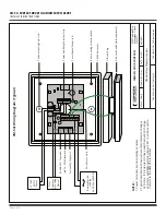
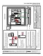
3. SETUP
Switch SW1 contains a bank of 3 dipswitches.
Dipswitch # 3 turns the speaker on or off. Dipswitch # 2 toggles
operation of the relay, and # 1 allows you to choose whether
the color will be changed locally via the push switch or remotely.
* NOTE:
The CX-12 Plus Multi-Function Relay may be used
with the Aura™, however an isolating relay must be wired in
parallel with the lock, and the relay’s dry contact output wired
into the CM-54i.
Switch Position Description
SW1
1
REMOTE / LOCAL On to enable
LED color change from idle to Active
with press of the push button.
2
RELAY On to enable operation of the
relay with activation of the push button.
3
SPEAKER On to enable operation of
the speaker with activation of the
push button.
Color selection is made with Switches SW2 and SW3. SW2
determines the Active color and SW3 determines the Idle color.
Setting the IDLE Color (SW2)
Switch Position Description
SW2
1
ON = Red LED when IDLE
2
ON = Green LED when IDLE
3
ON = Blue LED when IDLE
Setting the Active Color (SW3)
Switch Position Description
SW3
1
ON = Red LED when Active
2
ON = Green LED when Active
3
ON = Blue LED when Active
NOTE: If all DIP switches are in the OFF position, there will
be no color illuminated. This allows for no Idle color or no
Active color.
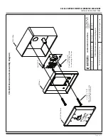
Once all DIP switches are set, proceed to Section 4 – Installation.
1
- CM-54i
1
- Red / Green / Blue Aura PCB
2
- #6 x 3/8 Screws
THIS PACKAGE INCLUDES: