background image


PS-H1701 

Intel Atom D2550 17

” HMI System   


User

’s Manual 


Version 1.0 


C&T

 Solution Inc. 

12F. -1, No.700, Zhongzheng Rd., Zhonghe Dist., New Taipei City 235, Taiwan 

TEL: 886-2-77317888                                                                                     

http://www.candtsolution.com 

Summary of Contents for PS-H1701 HMI

Page 1: ...PS H1701 Intel Atom D2550 17 HMI System User s Manual Version 1 0 C T Solution Inc 12F 1 No 700 Zhongzheng Rd Zhonghe Dist New Taipei City 235 Taiwan TEL 886 2 77317888 http www candtsolution com...

Page 2: ...4 1 Install Memory Module and SATA HDD 4 1 1 Install Memory Module 4 1 2 Install SATA HDD 4 2 Mounting Bracket Installation 4 2 1 Din Rail Installation 4 2 2 VESA Mount Installation 4 3 Panel Mount In...

Page 3: ...IO Header GPIO 5 5 8 Front Panel Header JW_FP1 5 5 9 Front Panel Audio Header AUDIO1 5 5 10 CIR Header CIR 5 5 11 CPU FAN Header CPUFAN1 5 5 12 LVDS Inverter INVERTER1 5 5 13 LVDS Inverter INVERTER2 V...

Page 4: ...PS H1701 Intel Atom D2550 17 HMI System 6 3 2 South Bridge 6 4 Boot 6 5 Security 6 6 Save and Exit VII Address Map 7 1 I O Port Address Map 7 2 Interrupt Controller IRQ Map 7 3 Memory Map...

Page 5: ...r s Manual Users must take full responsibility for the application of the product 1 2 Copyright Notice All rights reserved No part of this manual may be reproduced or transmitted in any form or by any...

Page 6: ...d shall be easily accessible Turn off the system power and disconnect the power cord from its source before making any installation Be sure both the system and the external devices are turned OFF Sudd...

Page 7: ...clock circuit There is a danger of explosion if incorrectly replaced Replace only with the same or equivalent type recommended by the manufacturer If one of the following situation arises get the equi...

Page 8: ...m also provides optimal shock vibration and temperature resistance The powerful CPU with integrated graphic engine provides a resolution up to 1280 x 1024 pixels With Intel NM10 chipset two Ethernet p...

Page 9: ...r Hardware reset 1sec 65535sec min 1 sec or 1 min step H W Monitor LCD Display Graphic processing unit GPU integrated with CPU 17 TFT LCD Resolution SXGA 1280x1024 Brightness 350 cd m2 Touch Screen US...

Page 10: ...for RS 232 USB Interface Five USB 2 0 connectors Power Input One 12V DC jack External 12V 5A 60W AC DC power adapter Expansion Interface One Mini PCIe Storage One 2 5 SATA HDD driver bay One CFast so...

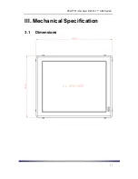
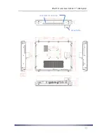
Page 11: ...PS H1701 Intel Atom D2550 17 HMI System III Mechanical Specification 3 1 Dimensions...

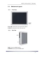
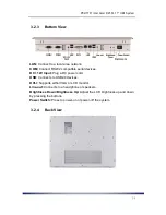
Page 12: ...PS H1701 Intel Atom D2550 17 HMI System reserved for antenna detachable...

Page 13: ...MI System 3 2 Mechanical Layout 3 2 1 Front View Power LED Indicates the power status of the system HDD LED Indicates the status of the hard drive 3 2 2 Side View USB Connects to USB2 0 devices DVD RO...

Page 14: ...ial devices DC 12V Input Plug a DC power cord USB Connects to USB2 0 devices DVI I Supports either VGA or LCD monitor Line out Connects to a headphone or speakers Brightness Down Brightness Up Adjust...

Page 15: ...ide down and remove the 12 screws 1 10 at the back and 2 at the bottom Step 2 Remove the rear cover 4 1 1 Install Memory Module Step 3 Remove the two screws 3 of the DVI D connector at the bottom I O...

Page 16: ...ystem Step 7 Insert the plated side of the memory module into the socket Step 8 Push the module down until it is firmly locked by two latches Step 9 Put the SBC back and fasten all screws Step 10 Clos...

Page 17: ...emove the rear cover use four screws to install a pair of HDD brackets at two sides of a 2 5 SATA HDD as illustrated in the diagram below Step 4 Use four screws to mount the HDD inside the panel Step...

Page 18: ...l Installation Step 1 Use four screws to install the bracket A at the back as indicated in the diagram below Make sure the latches of the bracket are facing down Step 2 Install the bracket B onto the...

Page 19: ...PS H1701 Intel Atom D2550 17 HMI System Step 4 Insert the security screw at the bottom of the din rail base as indicated in the diagram below...

Page 20: ...screws to install the bracket A at the back of the panel as indicated in the diagram below Make sure the latches of the bracket are facing down Step 2 Install the bracket B onto the desired surface fo...

Page 21: ...PS H1701 Intel Atom D2550 17 HMI System Step 4 After attaching the panel PC to the surface make sure the security screw is properly inserted as illustrated below...

Page 22: ...anel mounted The cutout of the panel is a 387mm x 317mm square as shown below Note the thickness of the panel and the Panel Mount Seal together is 9 3mm maximum Step 1 Place the panel front side down...

Page 23: ...PS H1701 Intel Atom D2550 17 HMI System Step 3 Place the Panel Mount Seal down inside the edge of the panel PC...

Page 24: ...PS H1701 Intel Atom D2550 17 HMI System Step 4 Place the panel on top of the Seal Step 5 Insert the eight brackets back into the panel PC as shown below Step 5 Fasten eight screws on the brackets...

Page 25: ...VCC 12V 5V Select JP3 LVDS2 5V 3 3V Select JP4 Inverter2 VCC 12V 5V Select JCOMP1 COM1 Header Pin9 Function Select JCOMP2 COM2 Header Pin9 Function Select JCOMP3 COM3 Header Pin9 Function Select JCOM...

Page 26: ...Defaults 2 3 closed 5 2 2 JP1 3 LVDS1 2 VCC 5V 3 3V Select Function Setting Jumper 5V Default 1 2 closed 3 3V 2 3 closed 5 2 3 JP2 4 Inverter1 2 VCC 12V 5V Select Function Setting Jumper 12V Default 1...

Page 27: ...JP5 COM 4 RS232 422 485 Function Select Function Setting Jumper RS232 Default 1 2 closed RS485 3 4 closed RS422 5 6 closed 5 2 6 COPEN Case Open Message Display Function Select Function Setting Jumpe...

Page 28: ...Front Panel Audio Header SATA II Port LVDS1 Header DC 12V Power in Connector DVI I Port RJ 45 LAN Port RJ 45 LAN Port USB 2 0 Ports CIR Header INVERTER2 USB 2 0 Ports INVERTER1 LVDS2 Header Mini PCIE...

Page 29: ...22 485 Header USB3 USB4 USB Headers GPIO1 GPIO Header AUDIO1 Front Panel Audio Header JW_FP1 Front Panel Header PWR LED HDD LED Power Button Reset CIR CIR Header CPUFAN1 CPU FAN Header INVERTER1 INVER...

Page 30: ...l Green link1 17 TMDS Data0 Digital Blue link1 Digital Sync 2 TMDS Data2 Digital Red link1 10 TMDS Data1 Digital Green link1 18 TMDS Data0 Digital Blue link1 Digital Sync 3 Data2 4 Shield 11 Data1 3 S...

Page 31: ...6 MDI2 3 MDI1 7 MDI3 4 MDI1 8 MDI3 A Active LED Yellow B 10 LAN LED OFF 100 LAN LED Green 1000 LAN LED Orange 5 4 5 COM Connector RS 232 Pin Signal Pin Signal 1 DCD Data Carrier Detect 6 DSR Data Set...

Page 32: ...tor PWOUT1 Pin Signal 1 5VSB 2 CIR_RX 3 GND 4 CIR LED 5 5 4 Serial Port Headers COM1 COM2 COM3 COM4 Pin Signal Pin Signal 1 DCD Data Carrier Detect 2 RXD Receive Data 3 TXD Transmit Data 4 DTR Data Te...

Page 33: ...Pin Signal 1 GPIO0 2 GPIO1 3 GPIO2 4 GPIO3 5 GPIO5 6 GPIO7 7 GPIO32 8 GPIO33 9 GND 10 5V 5 5 8 Front Panel Header JW_FP1 Pin Signal Pin Signal 1 VCC5 HDD LED 2 VCC5 PWR LED 3 HDDLED 4 PWRLED 5 GND RE...

Page 34: ...AN1 Pin Signal 1 GND 2 12V Fan Power 3 Fan Speed Dec 5 5 12 LVDS Inverter INVERTER1 Pin Signal 1 Backlight Enable 2 Backlight Duty 3 PVCC 4 PVCC 5 GND 6 GND 7 Backlight SW 8 Backlight SW 5 5 13 LVDS I...

Page 35: ...puter and press DEL or F2 to enter the setup screen There are six menu bars on top of BIOS screen Main To change system basic configuration Advanced To change system advanced configuration Chipset To...

Page 36: ...System 6 1 Main The Main setup screen is showed as following when the setup utility is entered System Date Time is set up in the Main Menu System Date MM DD YYYY System Time HH MM SS Use Tab to switc...

Page 37: ...OpROM Enable or Disable Boot Option for Legacy Mass Storage Devices with Option ROM Onboard LAN 1 Controller Enable or Disable PCI Express Root Port 1 Onboard LAN 2 Controller Enable or Disable Mini P...

Page 38: ...tel Atom D2550 17 HMI System 6 2 1 ACPI Settings ACPI Sleep State Select the highest ACPI sleep state the system will enter when the SUSPEND button is pressed Select between Suspend Disabled or S3 Sus...

Page 39: ...p Function Settings Wake System with Fixed Time Enable or disable System wake on alarm event When enabled System will wake on the hr min sec specified CIR Wake Enable or Disable CIR Wakeup This functi...

Page 40: ...g Technology and Disabled for other OS OS not optimized for Hyper Threading Technology Execute Disable Bit XP can prevent certain classes of malicious buffer overflow attacks when combined with a supp...

Page 41: ...H1701 Intel Atom D2550 17 HMI System 6 2 4 SATA Configuration SATA Controller s SATA Ports 0 3 Device Names if Present and Enabled Configure SATA as Select a configuration for SATA Controller IDE or A...

Page 42: ...The time out value for Control Bulk and Interrupt transfers Select from 1 sec 5 sec 10 sec and 20 sec Device reset time out USB mass storage device Start Unit command time out Select from 10 sec 20 se...

Page 43: ...PS H1701 Intel Atom D2550 17 HMI System 6 2 6 Super IO Configuration CIR Controller Enable or Disable CIR Controller Case Open Detect Detect Case has already open or not Show message in POST...

Page 44: ...hen enabled the following sub items shall appear CPUFAN1 Full Speed Temp Set a temperature for CPUFAN1 to run at full speed when above this specific temperature CPUFAN1 Idle Temp Set a temperature for...

Page 45: ...l Port Enable or Disable Serial Port Change Settings Select an optimal setting for Super IO device Serial Port 4 Configuration Serial Port Enable or Disable serial port COM Change Settings Select an o...

Page 46: ...oltage IO Output Voltage Setting Select from 0 3V 0 4V 0 5V 0 6V 0 7V 0 8V 0 9V and 1 0V 6 2 10 Watchdog Configuration WatchDog Timer Control Used to enable or disable WatchDog Timer When enabled is s...

Page 47: ...PS H1701 Intel Atom D2550 17 HMI System 6 2 11 Shutdown Temperature Configuration Select the system shutdown temperature Select from Disabled 60C 140F 65C 149F 70C 158F 75C 167F...

Page 48: ...ation EIST Enable or Disable Intel SpeedStep CPU C state Report Enable or Disable CPU C state report to OS Enhanced C state Enable or Disable Enhanced CPU C state CPU Hard C4E Enable or Disable CPU Ha...

Page 49: ...PS H1701 Intel Atom D2550 17 HMI System 6 3 Chipset...

Page 50: ...has no effect if external graphics present Select from VBIOS Default DVI CRT DVI HDMI LVDS2 LVDS1 HDMI LVDS1 CRT LVDS2 CRT LVDS1 Panel Scaling Select the LCD panel scaling option used by the Internal...

Page 51: ...r USB 2 0 EHCI Support Enable or Disable USB2 0 EHCI Support High Precision Timer Enable or Disable the High Precision Event Timer SLP_S4 Assertion Width Select a minimum assertion width of the SLP_S4...

Page 52: ...Off Quiet Boot Enables or disables Quiet Boot option GateA20 Active Select between Upon Request and Always Upon Request GA20 can be disabled using BIOS services Always Do not allow disabling GA20 this...

Page 53: ...s password is set then this only limits access to Setup and is only asked for when entering Setup If ONLY the User s password is set then this is a power on password and must be entered to boot or en...

Page 54: ...saving the changes Discard Changes and Reset Reset system setup without saving any changes Restore Defaults Restore Load Default values for all the setup options Save as User Defaults Save the change...

Page 55: ...PS H1701 Intel Atom D2550 17 HMI System VII Address Map 7 1 I O Port Address Map The assignment of the I O port addresses of the PS H1701 under Windows 7 Ultimate 32bit is shown below...

Page 56: ...PS H1701 Intel Atom D2550 17 HMI System...

Page 57: ...PS H1701 Intel Atom D2550 17 HMI System 7 2 Interrupt Controller IRQ Map The interrupt controller map of PS H1701 under Windows 7 Ultimate 32bit is as shown below...

Page 58: ...PS H1701 Intel Atom D2550 17 HMI System...

Page 59: ...PS H1701 Intel Atom D2550 17 HMI System...

Page 60: ...PS H1701 Intel Atom D2550 17 HMI System 7 3 Memory Map The memory map of DRAM of PS H1701 under Windows 7 Ultimate 32bit is shown below...

Reviews: