background image

Mar 27 2014

Service Manual

iPF780/760/750 series

iPF785

Summary of Contents for image Prograf iPF780 Series

Page 1: ...Mar 27 2014 Service Manual iPF780 760 750 series iPF785...

Page 2: ...need arises In the event of major changes in the contents of this manual over a long or short period Canon will issue a new edition of this manual The following paragraph does not apply to any countri...

Page 3: ...uiring care to avoid combustion fire Indicates an item prohibiting disassembly to avoid electric shocks or problems Indicates an item requiring disconnection of the power plug from the electric outlet...

Page 4: ...ed to indicate Low The voltage value how ever differs from circuit to circuit In addition the asterisk as in DRMD indicates that the DRMD signal goes on when 0 In practically all cases the internal me...

Page 5: ...4 1 16 1 6 Basic Operation 1 17 1 6 1 Operation Panel 1 17 1 6 2 Display 1 18 1 6 3 Menu 1 19 1 7 Safety and Precautions 1 39 1 7 1 Safety Precautions 1 39 1 7 1 1 Moving Parts 1 39 1 7 1 2 Adhesion o...

Page 6: ...4 1 Outline 2 30 2 4 1 1 Overview 2 30 2 4 2 Main Controller 2 32 2 4 2 1 Main controller PCB components 2 32 2 4 2 2 Connectors and Pin Arrangement of Main controller PCB 2 34 2 4 2 3 HDD expansion P...

Page 7: ...Adjustment and Setup Items 4 52 4 5 1 Adjustment Item List 4 52 4 5 2 Procedure after Replacing the Carriage Unit or Multi Sensor 4 52 4 5 3 Procedure after Replacing the Feed Roller or Feed Roller E...

Page 8: ...RVICE MODE 7 1 Service Mode 7 1 7 1 1 Service Mode Operation 7 1 7 1 2 Map of the Service Mode 7 2 7 1 3 Details of Service Mode 7 10 7 1 4 e Maintenance imageWARE Remote 7 28 7 1 5 Viewing PRINT INF...

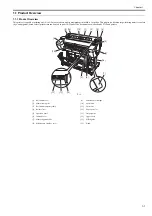
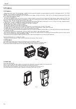
Page 9: ...Chapter 1 PRODUCT DESCRIPTION...

Page 10: ...ge 1 14 1 5 6 Ink Tank Cover Inside 1 15 1 5 7 Stand ST 34 1 16 1 6 Basic Operation 1 17 1 6 1 Operation Panel 1 17 1 6 2 Display 1 18 1 6 3 Menu 1 19 1 7 Safety and Precautions 1 39 1 7 1 Safety Prec...

Page 11: ...d colors printer that can be used to print CAD and office documents as well as handy POP and posters F 1 1 1 Roll media cover 9 Maintenance cartridge 2 Media loading slot 10 Cutter unit 3 Roll media t...

Page 12: ...requiring no installation space at the back of the printer A subtank mounted at the ink port allows you to replace the ink tank during printing The pressure of suction from the borderless printing ink...

Page 13: ...s paper tubes having inside diameters of both 2 and 3 inches It is furnished with attachments for 2 and 3 inch diameter paper tubes The roll holder clamps the paper tube of a roll not exceeding 150 mm...

Page 14: ...he regular position or two extended positions F 1 9 MEMO When delivering the printing to the output stacker Use the position A When not using the output stacker or moving the printer Use the position...

Page 15: ...to extended position A 1 Raise the auxiliary rod 1 to the position A of the illustration to change to the extended position A F 1 13 2 Pull out the switching stopper 1 when using roll paper that is A...

Page 16: ...ing illustration F 1 16 2 Open the output stacker ejection guides 1 toward the front F 1 17 Changing from the extended position B to regular position 1 Close the output stacker ejection guides 1 and p...

Page 17: ...ting after error occurrence If the printer encounters errors such as paper out while printing a print job it can resume the print operation as soon as the errors are cleared without needing its retran...

Page 18: ...5g Semiglossy Proofing Paper 255g Cut Paper Plain Paper Plain Paper High Quality Plain Paper High Grade Coated Paper Premiun Matte Paper Premium Glossy Paper 280 Premium Semi Glossy Paper 280 High Res...

Page 19: ...k cover open closed detection Yes Detection functions Ink passage system Ink tank presence absence detection Yes Remaining ink level detection dot count and electrode Yes Maintenance cartridge presenc...

Page 20: ...e 100 m or shorter Compliant with ANSI EIA TIA 568A or ANSI EIA TIA 568B 4 Interface connector Printer side Compliant with IEEE802 3 ANSI X3 263 ISO IEC60603 7 5 Protocol IPX SPX Netware4 2 J 5 1 J 6...

Page 21: ...to align media 8 Maintenance cartridge cover Open this cover to replace the maintenance cartridge 9 Maintenance cartridge This cartridge absorbs the ink used for maintenance Replace it when it becomes...

Page 22: ...en the Ethernet cable is connected properly and the printer is ready to communicate accordingly 3 USB port Connect the USB cable to this port This port is compatible with the high speed USB 4 Carrying...

Page 23: ...ent to perform printing Suction holes are provided on the platen surface to prevent media from floating 5 Borderless printing ink catch groove Ink flowed out of the paper edges enter in this groove du...

Page 24: ...uide 4 Roll holder slot Fit the roll holder in this slot 1 5 5 Carriage 0023 1267 F 1 26 1 Slant adjusting lever This lever is used to fine adjust slant of rules lines 2 Printhead The printhead has no...

Page 25: ...each ink tank according to the label color and name 3 Ink tank lamp red When the ink tank is opened the ink tank lamp illuminates as follows Stays lit The ink tank is loaded properly Not lit No ink t...

Page 26: ...the paper size when using the output stacker in the extended position A 5 Paper guide This guide is used to lead the ejected printout to the output stacker 6 Output stacker handle This handle is grasp...

Page 27: ...on Pressing this button in a menu displays the upper item or setting value button Pressing this button on the tab selection screen moves the tab When a menu requiring you to enter a value is selected...

Page 28: ...rse video pressing the OK button displays the Ink menu A Top field of display Shows the ink icon in reverse video B Middle field of display Shows the printer status and a menu name C Bottom field of d...

Page 29: ...y to select a menu and press the OK key The menu is selected and menu items are displayed Select a menu with on the left side and press the OK key to navigate to lower level menus b Setting menu items...

Page 30: ...played here Chg Paper Size Cut Sheet Size The size of paper is displayed here CustomPaperSize Set the length Roll Length 1 Set the length ManageRemainRoll Off On Pap Detail Set The paper type is displ...

Page 31: ...Scan Wait Time Dry time Off 1 sec 3 sec 5 sec 7 sec 9 sec Area 16 Entire area Leading edge Roll DryingTime Off 30 sec 1 min 3 min 5 min 10 min 30 min 60 min NearEnd RollMrgn 3mm 20mm NearEnd Sht Mrgn...

Page 32: ...s been set Job List Print Delete Print Job List Job Log Choose from information about the latest three print jobs Document Name User Name Page Count Job Status OK CANCELED Print Start Time yyyy mm dd...

Page 33: ...anced Manual 4 Head Inc Adj Feed Priority Adj Priority Automatic Print Quality Print Length Adj Quality 5 Auto GenuinePpr Auto OtherPaper Manual Adjust Length 6 AdjustmentPrint A High B Standard Draft...

Page 34: ...AD 5 Print Quality Draft Standard High Input Resolution 600dpi 300dpi Print Economy Off On Paper Manager Paper Source Automatic Roll Paper Cut Sheet Margin 3mm Standard 5mm Oversize Off On Conserve Pa...

Page 35: ...e B Choose a pen number Indicates Width Color and Line Attributes Specify the values of Width Color and Line Attributes Factory Choose a pen number Indicates Width Color and Line Attributes Reset Pale...

Page 36: ...the Address DNS Settings 13 DNS Dync update On Off Pri DNS SrvAddr Set the Address Sec DNS SrvAddr Set the Address DNS Host Name Set the DNS host name DNS Domain Name Set the DNS domain name IPv6 IPv...

Page 37: ...address is displayed here Interface Print 12 Return Defaults 12 System Setup Sleep Timer 5 min 10 min 15 min 20 min 30 min 40 min 50 min 60 min 210 min Shut Down Timer Off 5 min 10 min 30 min 1 hour 4...

Page 38: ...wCaledonia 12 Wellington 12 Eniwetok 11 Midway is 10Hawaii AHST 9 Alaska AKST 8 Oregon PST 7 Arizona MST 6 Texas CST 5 NewYork EST 4 Santiago 3 Buenos Aires 2 CenterAtlantic 1 Cape Verde Length Unit m...

Page 39: ...e for administrators only 14 Displayed only on models equipped with HDD 15 Displayed only on models not equipped with HDD 16 Leading edge is not available as a setting option in the Paper Detailed Set...

Page 40: ...ring printing The structure of the main menu during printing is as follows First Level Second Level Third Level Fourth Level Fifth Level Adj Fine Feed Printer Info Paper Info Ink Info Head Info System...

Page 41: ...ne at the cut position This option reduces the amount of debris given off after cutting It also helps prevent adhesive from sticking to the cutter and keeps the cutter sharp if you use adhesive paper...

Page 42: ...itted the job Page Count Display the number of sheets of the job Job Status Display the result of processing of the job Print Start Time Display the time at which the job started printing Print End Ti...

Page 43: ...cally adjusted from the printed result Auto OtherPa per Set when using paper not described in the paper reference guide A pattern to adjust the paper feed amount is printed and the feed amount is auto...

Page 44: ...This corresponds to the case where the PageSizeProcess 1 function in the old menu is set to On Conserve Paper Print by economizing on paper Auto Rotate If a document has its long side shorter than the...

Page 45: ...ct the width of lines The basic line width is set using the Pen Setup funstion Select Black gray to correct the width of lines whrere all of the RGB values are the same except when R G B 255 The setti...

Page 46: ...Specify the DNS domain name IPv6 IPv6 Support Set whether to support IPv6 connection IPv6 StlessAddrs Set whether to use IPv6 stateless address DHCPv6 Set whether to use DHCPv6 setting DNS Settings D...

Page 47: ...ich roll width to use if the roll width is between 10inch 254mm and JIS B4 257mm Keep Paper Size Select On to give priority to paper size If the margin set with the printer driver is less than the mar...

Page 48: ...ditionally the log is not printed if you choose Job Menu Print Job Log Note that because job logs are not collected the Status Monitor accounting functions will not work correctly Prep MovePrinter Sta...

Page 49: ...e feed motor the pinch roller and the purge unit driven by the purge motor To prevent accidents the upper cover of the printer is locked during printing If the top cover is opened in the online offlin...

Page 50: ...sh them with water well and see a doctor In case of accidental ingestion of a large quantity of ink see a doctor immediately It is also effective to use gloves to prevent ink from adhering when workin...

Page 51: ...n controller power supply HDD and interface connector The carriage PCB is incorporated in the carriage unit and the operation panel is on the upper right top cover When serving the printer with the co...

Page 52: ...ng standby due to an error in order to protect the printhead and avoid ink leakage If the power cord is accidentally unplugged turn off the Power button reconnect the power cord and then turn on the P...

Page 53: ...press down the ink tank cover the needle enters the ink port allowing ink to flow between the printer and ink tank Do not raise or lower the ink tank cover except when replacing the ink tank F 1 37 1...

Page 54: ...until the error is cancelled Be careful that the waste ink does not splash when you remove the used maintenance cartridge from the printer MEMO This printer has an EEPROM in the maintenance cartridge...

Page 55: ...ber of cleanings 4 On replacement of supplies After supplies have been replaced execute INITIALIZE PARTS COUNTER PARTS xx in service mode to initialize clear the parts counter information For the cons...

Page 56: ...with a lithium battery to back up various data Risk of explosion if battery is replaced by an incorrect type Dispose of used batteries according to the instructions For CA USA Only Included battery co...

Page 57: ...Chapter 2 TECHNICAL REFERENCE...

Page 58: ...nit 2 13 2 3 2 3 2 Structure of Carriage Unit 2 14 2 3 2 4 Printhead 2 17 2 3 2 4 1 Structure of Printhead 2 17 2 3 2 5 Purge Unit 2 18 2 3 2 5 1 Functions of Purge Unit 2 18 2 3 2 5 2 Structure of Pu...

Page 59: ...upply 2 47 2 4 5 1 Power supply block diagram 2 47 2 4 5 2 Connectors and Pin Arrangement of Power supply PCB 2 48 2 5 Detection Functions with Sensors 2 49 2 5 1 Covers 2 49 2 5 2 Ink passage system...

Page 60: ...ver IC2501 LAN Controller HDD Expansion PCB HDD IC201 HDD Controller J101 IC301 IC302 SDRAM J3001 J4501 Solenoid Feed Roller HP Sensor Feed Roller Encoder Sensor Lift Cam Sensor Paper Detection Sensor...

Page 61: ...on the printheads and the printer temperature from the latch IC on the carriage board and transmit them to the ASIC IC1 The ASIC IC1 also receives mask pattern data from the firmware installed in flas...

Page 62: ...0 20 or 10 nozzle blocks according to the Block Enable information in the even numbered nozzle data and odd num bered nozzle data Each selected block of nozzles is impressed with a Heat Enable signal...

Page 63: ...g signal internal signal which is generated by dividing the ENCODER_A signal detected at the 150 dpi timing into 16 equal sections Printing in the forward direction is triggered at the leading edge of...

Page 64: ...feed system initialization Recovery system initialization Carriage position initialization Remaining ink level detection Waste ink level detection Power on automatic recovery operation Capping Waiting...

Page 65: ...ion and shuts down immediately Since printhead capping may or may not have been carried out properly reconnect the power cord to the wall out and turn on the power switch Making sure that the printer...

Page 66: ...ing to that temperature Protection level 1 If the head temperature sensor DI sensor detects a temperature higher than the protection temperature it halts the carriage temporarily at the scan end posit...

Page 67: ...disk so it can resume the print job without having to retransmit the job from the host computer to it 3 Job preservation Print jobs are in the common box a place of temporary data storage and in the p...

Page 68: ...carriage unit having the printhead the purge unit the maintenance cartridge and the tube unit which are used to supply circulate and suck ink The paper path consists of the feed roller unit to suppor...

Page 69: ...to the maintenance cartridge If all of ink passages are opened no ink tank is installed the ink supply valve is opened and the printhead fixer lever is opened when the ink tube is being filled with in...

Page 70: ...s the ink port covered with a rubber plug establishing an ink passage between the printer and ink tank c Air passage When the ink tank lever of the printer is pressed down the hollow needle enters the...

Page 71: ...prevent ink leakage from occurring when the ink tube on the ink tank side is opened during replacement of the ink tank The ink supply valve is opened and closed by the valve open close mechanism whic...

Page 72: ...to adjust the head height automatically according to the selected media type media supply method printing conditions borderless priority print type environmental conditions temperature humidity and th...

Page 73: ...ting Adjust Printer from the main menu to shift the print timing A DC operated carriage motor drives the carriage reciprocally on the platen by way of the carriage belt The carriage home position or t...

Page 74: ...r forward F 2 13 h Multi Sensor A photo reflective type multi sensor consists of three red LEDs one red blue green LED array and three light receiving sensors and is used for media end skew and width...

Page 75: ...Chapter 2 2 16 j Internal temperature detection A themistor for measuring the internal temperature is mounted on the carriage PCB on the rear of the head holder...

Page 76: ...0 nozzle arranged at intervals of 1200 dpi F 2 14 b Nozzle structure Ink supplied from the ink tank is filtered by a mesh ink filter and the supplied to the nozzles Ink is supplied from the shared ink...

Page 77: ...tween the printhead and purge unit b Cleaning function The cleaning function restores the printhead to the state where ink can be easily discharged from nozzles This function includes the following th...

Page 78: ...r secondary transport Cleaning 6 CLN A 6 CLN M 6 Head Cleaning B Normal strong cleaning Performs suction stronger than when adjusting the ink filling amount in the head or normal cleaning to unclog no...

Page 79: ...ing after head replacement 10g No heads are available Cleaning 10 ink filling on secondary transport 60g Power off Specified number of dots discharged per chip completed since the last session of wipi...

Page 80: ...printhead six arrays of nozzles installed in the carriage During cleaning the caps used for both suction and capping are used to suck ink from the printhead using the suction pump During capping the...

Page 81: ...is pressed against the wiper blades to enhance the wiping performance The amount of glycerin used tank capacity 50 ml is managed by counting the number of times the wiper blade is pressed against the...

Page 82: ...y full Printing may continue even when the warning message is displayed When the quantity of the used ink reaches about 893 ml 100 of the cartridge capacity a replacement prompt error message is displ...

Page 83: ...platen and each is connected to the platen suction fan One comes from the borderless printing ink receiving grooves and the other comes from the suction port The duct from the borderless printing ink...

Page 84: ...open Yes 17 inch or shorter media 2 Fully open Yes B2 or larger media Yes 3 Fully close Yes 4 1 4 open Yes 5 1 2 open Yes 6 3 4 open Yes 1 3 4 5 6 2 2 Shutter Motor Shutter Shutter HP Sensor Borderles...

Page 85: ...sure drive unit that pressurizes and depressurizes the pinch roller a roll holder drive unit that drives the roll holder and sensors that detect the transport status of paper to feed paper in one way...

Page 86: ...nch roller unit operating in conjunction with the feed rollers While being held flat on the platen media is fed horizontally under the printhead b Detection Unit The feed roller unit has a sensor that...

Page 87: ...d and assumes the end of roll media is reached when the roll holder stops rotating d Release lever unit The release lever is used to release the pinch roller pressure when setting the media or fixing...

Page 88: ...n Whether cutting takes place or not depends on the relevant printer driver setting in the main menu The cutter in the cutter unit stands by at the cutter home position except when a roll media is cut...

Page 89: ...nted on the rear side of the printer the carriage PCB and printhead which are mounted in the carriage and other electrical components such as the operation panel sensors and motors The main controller...

Page 90: ...nction Sensors Fans Maintenance Cartridge Relay PCB Motor control function Motors Host Computer Ink Tank ROM PCB Interface control function DI Sensor reading control function Temperature reading contr...

Page 91: ...ignal to the nozzle heater board for each printhead nozzle array Linear scale count function This function reads the linear scale when the carriage moves thus generating the ink discharge timing It al...

Page 92: ...alve motor L R control signals based on the control signal from the ASIC f DIMMs IC301 IC302 IC601 IC602 IC603 IC604 The DIMM comprising a 512 MB DDR SDRAM IC301 IC302 and 256 MB SDR SDRAM IC601 IC602...

Page 93: ...nsmission line 6 NETWK OUT1 N IN OUT Ethernet data reception line 7 NETWK OUT3 P IN OUT Ethernet data transmission line 8 NETWK OUT3 N IN OUT Ethernet data transmission line 9 3 3V OUT Power supply 3...

Page 94: ...ber Signal name IN OUT Function 1 PUMPM_OUTA OUT Purge motor drive signal A 2 PUMPM_OUTB OUT Purge motor drive signal B 3 PUMP_ENCB IN Pump encoder sensor output signal B 4 SNS5V_FU1 OUT Power supply...

Page 95: ...201 Ink detection sensor R Ink supply valve open closed detection sensor R Ink tank cover switch R Cutter HP sensor Pin Number Signal name IN OUT Function 1 SNS_CURRENT1 OUT Sensor current control sig...

Page 96: ...VH OUT Power supply 21 5V 15 VH OUT Power supply 21 5V 16 VH OUT Power supply 21 5V 17 VH OUT Power supply 21 5V 18 VH OUT Power supply 21 5V 19 VH OUT Power supply 21 5V 20 VH OUT Power supply 21 5V...

Page 97: ...0 FFC SLANT DET SNS1 IN FFC disconnection detection signal 1 J3602 Connect to Carriage PCB J102 Pin Number Signal name IN OUT Function 1 FFC_SLANT_DET_SNS4 IN FFC disconnection detection signal 4 2 ED...

Page 98: ...OUT Power supply 5V 4 LF_ENCB IN Feed roller encoder sensor output signal B 5 SNS3V_FU1 OUT Power supply 3 3V 6 GND GND 7 LF_HP_SNS IN Feed roller HP sensor output signal 8 UMF3V OUT Power supply 5V 9...

Page 99: ...ion 1 INKBEN_L_OUTB OUT Valve motor L drive signal B 2 INKBEN_L_OUTA OUT Valve motor L drive signal A 3 VM_26V 26 5V OUT Power supply 26 5V 4 DCOVER_SOL OUT Upper cover lock solenoid drive signal 5 SN...

Page 100: ...based on the control signals from the main controller Environmental temperature reading control This function sends the environmental temperature detected by the thermistor on the board based t the ma...

Page 101: ...head data signal 7 D 21 GND GND 22 H1 D DATA 6 EV IN Even head data signal 6 D 23 GND GND 24 H1 D HE 6 IN Head heat enable signal 6 D 25 GND GND 26 H1 D DATA 6 OD IN Odd head data signal 6 D 27 GND GN...

Page 102: ...GND GND 28 H1 A DATA 0 OD IN Odd head data signal 0 A 29 GND GND 30 H1 A DATA 1 OD IN Odd head data signal 1 A 31 GND GND 32 H1 B HE 2 IN Head heat enable signal 2 B 33 GND GND 34 H1 B DATA 2 OD IN Od...

Page 103: ...ATA 1 EV OUT Even head data signal 1 A 37 H1 A DIA2 IN Head DI sensor signal 2 A 38 H1 B DIA2 IN Head DI sensor signal 2 B 39 H1 C HE 4 OUT Head heat enable signal 4 C 40 H1 D DATA 7 OD OUT Odd head d...

Page 104: ...3 3V 18 VH_SW1_ON IN VH control signal 19 21V_H1_VHT IN Power supply 21V 20 5V_VM_IC IN Power supply 5V 21 GND GND 22 VHGND GND 23 VHGND GND 24 VHGND GND 25 VHGND GND J202 Linear encoder sensor Pin Nu...

Page 105: ...2 4 4 Maintenance Cartridge Relay PCB 2 4 4 1 Maintenance cartridge relay PCB components 0023 2553 F 2 34 a EEPROM IC1 The 256 KB EEPROM stores all information written to the EEPROM on the main contr...

Page 106: ...ans and sensors and a 21 5 V generator circuit for driving sensors heads logic circuits and others When the power is turned off 26 V and 21 5 V are reduced to about 12 V and 9 V respectively power sav...

Page 107: ...AC N Power supply AC120V or AC230V CN2 Connect to Main controller PCB Pin Number Signal name IN OUT Function 1 PW_CONT IN Normal power saving switch signal 2 VM 32V OUT Power supply 32V 3 VM 32V OUT P...

Page 108: ...When the upper cover close the switch is pressed to detect the closed state of the upper cover Ink tank cover switch L R The microswitch based ink tank cover switches detect the open closed states of...

Page 109: ...ter 2 2 50 2 5 2 Ink passage system 0031 2546 F 2 38 Ink Supply Valve Open Closed Detection Sensor L R Ink Detection Sensor L R Head Management Sensor Shutter HP Sensor Pump Encoder Sensor Pump Cam Se...

Page 110: ...conjunction with the ink supply valve cam shields light this sensor detects that the ink supply valve has been opened Ink detection sensor L R Presence of absence of ink in the ink tank is detected ac...

Page 111: ...pecified number of non discharging nozzles are located in the second session of non discharging nozzle detection the normal High cleaning session is launched before a third session of non discharging...

Page 112: ...nt temperature sensor mounted on the carriage PCB detects the ambient temperature to which the carriage is exposed The resistance of the thermistor that varies as a function of temperature changes in...

Page 113: ...end of media detection The head height is detected by receiving the reflection of red LED from the media with two sensors in a light receiving sensor and calculating the difference in measurements Th...

Page 114: ...rate of paper transport per revolution of the feed roller from slits in the encoder during driving Release lever lock sensor A photointerrupter type sensor This sensor detects the release lever lock s...

Page 115: ...ghtmost position Cutter left position sensor The photointerrupter type sensor detects the presence of the cutter at the leftmost position Pinch roller pressure release switch A micro switch type pinch...

Page 116: ...detection sensor detects the temperature and relative humidity around the printer to implement head height adjustment maintenance jet control waste ink evaporation calculation and suction fan control...

Page 117: ...Chapter 3 INSTALLATION...

Page 118: ...Contents Contents 3 1 Transporting the Printer 3 1 3 1 1 Transporting the Printer 3 1 3 1 1 1 Transporting the Printer 3 1 3 1 2 Reinstalling the Printer 3 6 3 1 2 1 Reinstalling the Printer 3 6...

Page 119: ...of transportation Select the appropriate transportation level from the following transportation modes 1 Transportation mode Moving the printer on the same floor with no difference in grade without ti...

Page 120: ...an cause ink leakage or damage to the printhead Be sure to move the printer slowly and care fully Do not incline the printer during transportation The internal ink may leak and the surrounding area ma...

Page 121: ...ption Prep MovePrinter on the Main menu Perform Limited Allowed tilting angle Lengthwise 30 to 30 degrees Rotation 30 to 30 degrees Ink consumption Approximately 130 to 580ml of ink is consumed accord...

Page 122: ...nter is subjected to strong vibrations when it is moved it can cause ink leakage or damage to the print head Be sure to move the printer slowly and carefully Item Description Prep MovePrinter on the M...

Page 123: ...king box for moving Use the original packing material for the printer and stand If it is not available pack them with a sufficient amount of cushioning materials 3 Manual capping When transporting the...

Page 124: ...location 2 Installing the printer on a different floor If ink has been drained when transporting the printer to a different floor follow the installation procedure below It is nearly identical to the...

Page 125: ...Chapter 4 DISASSEMBLY REASSEMBLY...

Page 126: ...3 8 Ink Tank Unit 4 25 4 3 9 Ink Tube Unit 4 29 4 3 10 Waste Ink Collection Unit 4 33 4 3 11 Multi Sensor 4 38 4 3 12 Linear Encoder 4 39 4 3 13 Head Management Sensor 4 44 4 3 14 PCBs 4 45 4 3 15 Ope...

Page 127: ...ually packaged service part carriage unit purge unit ink tank unit and other parts boxes marked This side up and handle appropriately F 4 1 2 Feed roller The feed roller is a functionally important pa...

Page 128: ...after initial factory adjustments are indicated by the presence of red screws Under no circumstance should these red screws be loosened or removed Removing these screws will render the printer out of...

Page 129: ...REASSEMBLY Points to Notes on Disassembly and Reassembly Draining the ink 1 Carriage unit Refer to DISASSEMBLY REASSEMBLY Points to Notes on Disassembly and Reassembly Carriage unit 2 Ink tube unit Re...

Page 130: ...r 2 Remove the cable from the cable guide and then remove the ground wire 5 by pushing the hook 4 from the backside of the operation unit and disconnect the connector 6 and then remove the operation p...

Page 131: ...eration panel 2 Remove six screws 1 release two hooks 2 and then remove the right cover 3 F 4 6 d Left Cover Removing the Left Cover 1 To remove the left remove the upper left cover 2 Remove six screw...

Page 132: ...hooks 4 by using the flat head screwdriver F 4 8 f Output Guide Removing the Output Guide 1 To remove the output guide open the maintenance cartridge cover 1 to remove the maintenance cartridge 2 and...

Page 133: ...Chapter 4 4 7 3 Remove one screw 1 release two hooks 2 and then remove the output guide middle left 3 F 4 11 1 3 2 2...

Page 134: ...ving the Left Right Ink Tank Cover 1 To remove the left right ink tank cover 2 remove the left right cover and front cover 2 Remove two screws 1 and then remove the left right inner cover 2 Left Inner...

Page 135: ...er 4 4 9 3 Remove the screw 1 and release the hook 2 and then remove the left right ink tank cover 4 while releasing two protrusions 3 Left Ink Tank Cover F 4 14 Right Ink Tank Cover F 4 15 1 4 3 2 1...

Page 136: ...over 1 to the left to remove it from the hinge 2 F 4 16 i Rear Upper Cover Removing the Rear Upper Cover 1 To remove the rear upper cover 3 remove the left right cover and upper cover open the roll co...

Page 137: ...1 F 4 19 k Roll Feed Unit Removing the Roll Feed Unit MEMO Open close the roll cover as needed 1 To remove the roll feed unit remove the roll holder and then remove the left right cover and rear upper...

Page 138: ...Chapter 4 4 12 3 Remove four screws 1 and then the left and right roll lower inner covers 2 Left roll lower inner cover F 4 21 Right roll lower inner cover F 4 22 2 1 1 2...

Page 139: ...ove three screws 1 and then remove the left roll cover 2 F 4 23 5 Remove seven screws 1 and three connectors 2 and then remove the cable from the cable guide to remove the roll feed unit 3 F 4 24 1 1...

Page 140: ...it 3 F 4 25 2 Remove one spring 1 and then the release lever 2 Keep the pinch roller pressurized to enable phase adjustment at the time of release lever reinstallation F 4 26 Precautions about Reinsta...

Page 141: ...has the feed roller eccentricity that is variations in the rate of paper feed from rotation to rotation corrected for enhanced media feed ac curacy When the feed roller HP sensor or feed roller encod...

Page 142: ...te on Disassembly and Reassembly Opening the Cap Moving the Wiper Unit 2 Remove the left right cover 3 Remove one screw 1 and then remove the carriage upper cover 2 F 4 30 4 Remove one screw 1 pulley...

Page 143: ...sted After reinstalling it check whether the carriage moves on the platen smoothly F 4 33 Reinstall the pulley retainer 1 in such a manner that it fits in the notch 2 on the side plate F 4 34 d Action...

Page 144: ...Motor 1 Remove the output guide right 2 Disconnect one connector 1 While releasing the hook 3 by pressing the protrusion 2 turn the shutter motor unit 4 slightly in the clockwise direction Remove the...

Page 145: ...return the cutter to the home position Then choose CLR COUNTER CT 1 YES that displayed on the LCD to initialize the parts counter information Removing the Cutter Rail Unit 1 Drain ink Refer to Draini...

Page 146: ...Chapter 4 4 20 4 Remove one screw 1 move the cutter rail unit 2 to the left to release it from two protrusion 3 and then remove it rightward F 4 38 1 2 3...

Page 147: ...y Opening the Cap Moving the Wiper Unit 2 Remove the right cover 3 Remove five screws 1 and disconnect five connectors 2 and then remove the cable from the cable guide to remove the right side plate u...

Page 148: ...talling the waste ink tubes attach the tubes surely until end of the joint And check that the tubes are not buckled F 4 42 a Drain ink tube joint CL Removing the drain ink tube joint CL 1 Open the mai...

Page 149: ...4 4 23 3 Remove twelve screws 1 and then remove the rear cover 2 F 4 45 4 Disconnect the connector 1 F 4 46 5 Remove two screws 1 and then remove the maintenance cartridge holder unit 2 F 4 47 1 1 1 1...

Page 150: ...oint CL 3 F 4 48 When removing the drain ink tube joint CL and the drain ink tube be careful so that the ink do not spout or drip Precautions about Reinstallation of drain ink tube joint CL When attac...

Page 151: ...2 Remove the right cover front cover and right ink tank cover 3 Remove four screws 1 and then remove the support plate 2 F 4 50 4 Remove four screws 1 and disconnect two connectors 2 and then remove...

Page 152: ...o prevent ink from spouting F 4 52 F 4 53 Removing the Left Ink Tank Unit 1 Perform ink drainage Refer to Disassembly Reassembly Points to Note on Disassembly and Reassembly Draining the ink 2 Remove...

Page 153: ...en remove the joint 3 between the ink tube unit and ink tank unit carefully and remove the ink tube from the guide and then remove the left ink tank unit 4 F 4 55 Remove the joint carefully so that in...

Page 154: ...e Motor Unit Removing the Valve Motor Unit 1 Remove the ink tank unit 2 Remove three screws 1 and disconnect two connectors 2 and then remove the cable from the cable guide to remove the valve motor u...

Page 155: ...eassembly Opening the Cap Moving the Wiper Unit 3 Remove the front cover 4 Move the carriage to the position where there is a notch 1 at the front of the platen as shown below F 4 59 5 Remove the prin...

Page 156: ...n the ink tube joint to prevent ink from spouting F 4 61 7 Remove two screws 1 and disconnect two connectors 2 and then remove the solenoid base 3 F 4 62 8 Remove two joint 1 between the ink tube unit...

Page 157: ...Chapter 4 4 31 Remove the joint carefully so that ink does not spout Put a plastic bag or the like on the ink tube joint to prevent ink from spouting F 4 64 F 4 65 F 4 66 F 4 67...

Page 158: ...ign marking 1 on the ink tube unit to the right end of guide 2 and the left end of tape 3 to within 4mm from the left end of tube guide 4 F 4 68 After detaching the joint of the ink tube unit the join...

Page 159: ...king box may include a plastic bag for packing replacement parts Use it for putting consumable parts of the waste ink collection unit F 4 69 1 Mist Fan F 4 70 No Name Q ty Part number Consumables Serv...

Page 160: ...Chapter 4 4 34 2 Mist Exhaust Duct F 4 71 3 Platen Suction Fan F 4 72 4 Platen Exhaust Duct F 4 73 5 Head Management Sensor F 4 74 A A A A...

Page 161: ...nk tank cover 2 Remove two screws 1 and disconnect the connector 2 and then remove the cable from the cable guide to remove the support plate 3 F 4 75 3 Remove four screws 1 and disconnect three conne...

Page 162: ...move the cable from the cable guide to remove the mist exhaust duct 2 F 4 77 MEMO The mist fan 1 and mist exhaust duct 2 can be removed together F 4 78 Precautions about Reinstallation of Mist Exhaust...

Page 163: ...nector 2 to remove the platen suction fan 3 F 4 80 3 After drawing out the platen suction fan 1 turn it up side down immediately so that ink does not drip off F 4 81 d Platen Exhaust Duct Removing the...

Page 164: ...he multi sensor in the carriage unit and the nozzles in the printhead is varied from one unit to another the printer as shipped has its optical axis corrected to adjust the image write position When t...

Page 165: ...d then remove the linear encoder sensor 3 F 4 86 Removing the Linear Scale 1 Unlock the carriage unit and then move the carriage unit 1 on the platen Refer to Disassembly Reassembly Points to Note on...

Page 166: ...left right ink tank cover 3 Remove one screw 1 and then remove the carriage upper cover 2 F 4 88 4 Remove the spring 1 release the notch from the protrusion 2 on the side plate and then remove the li...

Page 167: ...carriage unit to the HP side on top of the platen to prevent the linear scale from touching the linear encoder sensor Reinstall the linear scale in such a manner that the R mark on the linear scale i...

Page 168: ...42 Reinstall the linear scale in such a manner that it passes through the notch in the guide 1 and the notch 2 on the side plate F 4 91 Never touch the detection part 1 of the linear scale F 4 92 1 2...

Page 169: ...ncoder sensor 2 F 4 93 b Action to take after removing or replacing the linear encoder sensor After the carriage and carriage motor and carriage belt and linear encoder sensor has been removed or repl...

Page 170: ...ment sensor Since the distance between the head management sensor and the carriage unit varies among printers the optical axis is factory adjusted to adjust the non discharging detection position When...

Page 171: ...the Load and Navigate keys Start the printer in PCB replacement mode 4 Release the key but not before making sure that Initializing appears on the display The message lamp lights when printer enters...

Page 172: ...ixer lever is released with the ink supply valve to an ink tube open while the tube is filled with an ink the ink in the tube could flow backward to the ink tank unit leaking through the hollow needle...

Page 173: ...ure or any other trouble before the operation completes 2 Manual Ink Drain Drain the ink passage of inks manually if any electrical component in the printer fails or firmware malfunctions or if the pr...

Page 174: ...that grease do not get onto the wiper cap carriage shaft and the linear scale 1 Joint Base Rib 1 F 4 96 No Location Grease Quantity Remarks 1 Joint Base Rib FLOIL G 5000H Approx 8 20mg 2 Shaft Cleaner...

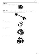
Page 175: ...Chapter 4 4 49 2 Shaft Cleaner 1 F 4 97 1 1...

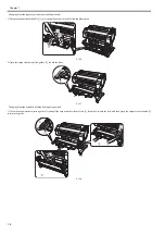
Page 176: ...Chapter 4 4 50 3 Upper Cover Hinge Catch 1 Roll Cover Slide Guide 2 F 4 98 2 1...

Page 177: ...Chapter 4 4 51 4 Contact between Pinch Roller Release Shaft and Pinch Roller 1 Pinch Roller Pressure Release Gear 2 Protrusion of Release lever 3 Bushing of Feed Roller 4 F 4 99 1 4 2 3 4 3...

Page 178: ...after Replacing the Feed Roller or Feed Roller Encoder 0012 6594 Feed roller eccentricity is factory adjusted correction of variation in the paper feed amount per rotation It is necessary to adjust f...

Page 179: ...Chapter 5 MAINTENANCE...

Page 180: ...ontents Contents 5 1 Periodic Replacement Parts 5 1 5 1 1 Periodic Replacement Parts 5 1 5 2 Consumable Parts 5 1 5 2 1 Consumable Parts 5 1 5 3 Periodic Maintenance 5 3 5 3 1 Periodic Maintenance 5 3...

Page 181: ...nging cam rotation Carriage Unit Removing the Carriage Unit CR5 MULTI SENSOR UNIT QM3 5831 1 14900 14850000 16500000 X100 dots W Level1 W Level2 Total ink discharge quantity Multi Sensor Removing the...

Page 182: ...ute INITIALIZE PARTS COUNTER PARTS xx in service mode to initialize clear the parts counter information Kit name Parts number Counter name Name MAINTENANCE KIT CR Mi QY6 1534 CR1 CARRIAGE UNIT CR3 CAR...

Page 183: ...en dry them finally with a dry cloth F 5 1 Be sure to turn off the printer power and pull out the power cord from the outlet If the power is accidentally turned on contact with moving internal parts c...

Page 184: ...ng Brush 3 to wipe it away F 5 3 MEMO If the Cleaning Brush is dirty rinse it in water 6 Using a damp cloth that you have wrung out completely wipe inside the Upper Cover to clean it Wipe away any ink...

Page 185: ...ts such as thinner and benzine on the printer Solvents coming into contact with any electrical parts inside the printer could result in fires or electrical shock hazards Do not touch linear scale 1 an...

Page 186: ...Chapter 6 TROUBLESHOOTING...

Page 187: ...1 Outline 6 1 6 2 2 Warning Table 6 2 6 2 2 1 Warnings 6 2 6 2 3 Error Table 6 6 6 2 3 1 Errors 6 6 6 2 4 Sevice Call Table 6 17 6 2 4 1 Service Call Errors 6 17 6 3 Service Software 6 18 6 3 1 L Pri...

Page 188: ...N cable at the service working be sure to enter the service mode to recognize the printer correctly 6 2 Error Code 6 2 1 Outline 6 2 1 1 Outline 0031 2603 The printer indicates errors using the displa...

Page 189: ...r HP GL 2 Check if there is the non image area of the print Verify the transmitted data before reprinting GARO W1221 01341221 1030 GARO image mode Unknown command Verify the transmitted data before re...

Page 190: ...01810109 141B No B ink tank warning Install the ink tank Ink tank is empty Replace the ink tank 01810301 1401 Y ink tank empty Renew the Y ink tank Ink tank is empty Replace the ink tank 01810302 140...

Page 191: ...printing move the blue platen switch 0186100A 1059 Platen shutter No 5 open warning Open the corresponding platen shutter Check the platen and multi sensor and surrounding parts Replace the multi sen...

Page 192: ...ot feed paper more Forced feed limit Check the remaining quantity of roll media Prepare for parts replacement Call for service Parts counter W1 level Check the parts counter in service mode Display me...

Page 193: ...ia Paper jam Lift the release lever and remove the paper 03010000 201D Paper left edge detection error roll media printing Set or replace the media Cannot print as specified Replace paper with A4 LTR...

Page 194: ...nual feeding slot Sheet printing is selected Press Load Eject and load sheets 03060200 2E03 No cassette paper Load cut sheet in the cassette Cassette printing is selected Press Load Eject and remove m...

Page 195: ...then turn on again 03130031 2F17 Platen suction fan lock detection error Check the platen suction fan Hardware error 03130031 2F1F Turn off printer wait then turn on again 03130031 2F1F Pump cam sens...

Page 196: ...31 2F51 VH leakage both printheads single printhead Replace printhead Hardware error 03130031 2F52 Turn off printer wait then turn on again 03130031 2F52 Carriage PCB of different model installed erro...

Page 197: ...rror Replace the left printhead Left printhead error Open top cover and replace the left printhead 03800202 2813 Printhead2 wrong version error Replace the left printhead Printhead L error Turn off pr...

Page 198: ...k the ink tube unit and surrounding parts Check the purge unit and surrounding parts Check the head management sensor and surrounding parts Check the flexible cable unit and surrounding parts Check th...

Page 199: ...k Remaining level of the ink cannot be correctly detected Check ink tank 03810104 2510 Unidentified status of BK ink tank refill ink tank detection Invalidate the ink remaining detection function or r...

Page 200: ...k Ink insufficient Press OK and replace ink tank 03810205 2598 Low on the GY ink tank during pre printing checks Replace with a fully replenished GY ink tank Ink insufficient Press OK and replace ink...

Page 201: ...Install the detached ink tank Remaining level of the ink cannot be correctly detected Check ink tank 03830107 251A Unidentified status of R ink tank refill ink tank detection Invalidate the ink remain...

Page 202: ...sheet Roll printing is selected but sheets are loaded Press OK remove the sheets and load a roll 03860002 2E0A Data with a roll media specification has been received when a cut sheet tray is loaded R...

Page 203: ...can be fed and reload the paper Paper position not suitable for borderless printing Fix Paper Position Print With Border Stop Printing 03864004 2409 Borderless printing disabled physical after resumin...

Page 204: ...controller PCB E196 4042 Flash memory write error when executing the firmware update Execute firmware update or replace the main controller PCB E196 4043 Memory error when executing the firmware upda...

Page 205: ...b menu button The sub menu button is displayed according to the menu choosed by main menu or main menu button 4 Printer information area The information of the printer connected with computer is shown...

Page 206: ...atus Print is shown by the appointed application software 3 3 Choose the Color Check of the sub menu button or the Information Color Check of the main menu when executing the color check This mode jud...

Page 207: ...dialogue box The five IP addresses at the maximum can register when searching by the IP address F 6 7 3 Choose the Specify Firmware of the sub menu button or the Firmware Specify Firmware of the main...

Page 208: ...the sub menu button or the Files Display of the main menu after selecting the list that want to show in the printer information area The multiple selection from the lists is possible The data of the...

Page 209: ...thod Selection dialogue box as shown in the followings 4 1 In case the computer is connected to the internet select the Connect to the internet to get the latest information and then click Next F 6 10...

Page 210: ...ion dialogue box F 6 14 8 The firmware data is transferred to the printer 9 After the firmware data transference has completed the Finish Update dialogue box is displayed Click the OK When the firmwar...

Page 211: ...d removing the spring parts Hex key wrench Inserting and removing hexagonal screws Flat brush Applying grease Special purpose tools Application Cover Switch Tool QY9 0103 Pressing the cover switch Gre...

Page 212: ...Chapter 7 SERVICE MODE...

Page 213: ...1 7 1 1 Service Mode Operation 7 1 7 1 2 Map of the Service Mode 7 2 7 1 3 Details of Service Mode 7 10 7 1 4 e Maintenance imageWARE Remote 7 28 7 1 5 Viewing PRINT INF 7 38 7 2 Special Mode 7 53 7...

Page 214: ...enu and press the OK key SERVICE MODE appears in the menu list and the MESSAGE LED flashes 5 Press the key or key to choose SERVICE MODE and press the OK key Service mode is added to the Set Adj Menu...

Page 215: ...elow First Level Second Level Third Level Fourth Level Fifth Level Sixth Level DISPLAY PRINT INF YES NO Select YES to print SYSTEM S N TYPE LF TYPE TMP RH SIZE LF SIZE LF SIZE CR SIZE CR AFTER INST HE...

Page 216: ...NUAL HEAD ADJ DETAIL Press the OK button to execute BASIC Press the OK button to execute ADJ SETTING A A 1 Adjustment value entry A 24 Adjustment value entry F F 1 Adjustment value entry SAVE SETTINGS...

Page 217: ...AN SIZE 1 Press the OK button to set 5 Press the OK button to set CR SCAN SPEED 1 Press the OK button to set 5 Press the OK button to set STIRRING CHECK YES NO OPT SENS OUTPUT YES OUTPUT0 OUTPUT6 NO N...

Page 218: ...DIST PRINT COUNT PURGE CLN A 1 CLN A 2 CLN A 3 CLN A 6 CLN A 7 CLN A 10 CLN A 11 CLN A 15 CLN A 16 CLN A 17 CLN A TTL CLN M 1 CLN M 4 CLN M 5 CLN M 6 CLN M TTL CLEAR CLR INK CONSUME CLR MTC EXC CLR H...

Page 219: ...CT 1 EXC WF 1 EXC WF 2 EXC DETAIL CNT MOVE PRINTER N INK CHK C N INK CHK BK MEDIACONFIG CNT INK USE1 INK USE1 C INK USE1 BK INK USE1 TTL LINK USE1 C LINK USE1 BK LINK USE1 TTL SINK USE1 C SINK USE1 BK...

Page 220: ...OLL CUTSHEET CUTSHEET MEDIA OTHER NAME TTL TTL ROLL ROLL CUTSHEET CUTSHEET MEDIASIZE1 ROLL P SQ 36 44 P SQ 36 44 P SQ 24 36 P SQ 24 36 P SQ 17 24 P SQ 17 24 P SQ 17 P SQ 17 P CNT 36 44 P CNT 24 36 P C...

Page 221: ...Q 17 24 P SQ 17 P SQ 17 P CNT 36 44 P CNT 24 36 P CNT 17 24 P CNT 17 MEDIASIZE2 CUT D SQ 36 44 D SQ 36 44 D SQ 24 36 D SQ 24 36 D SQ 17 24 D SQ 17 24 D SQ 17 D SQ 17 D CNT 36 44 D CNT 24 36 D CNT 17 2...

Page 222: ...ton to clear ERROR Press the OK button to clear JAM Press the OK button to clear ADJUST Press the OK button to clear W INK Press the OK button to clear CARRIAGE Press the OK button to clear PURGE Pres...

Page 223: ...event has the smallest history number Display Description Unit S N Serial number of printer TYPE Type setting on main controller PCB iPF786 785 781 780 is represented by 36 LF TYPE Feed roller type 0...

Page 224: ...2 Jam 3 Feed failure delay 4 Cut failure 0 Unknown 2 Media 1 Roll media 2 Cut sheet 0 Unknown 3 Jam timing 1 Feed 2 Print 3 Eject 0 Unknown 4 Media width detection 1 ON 2 OFF 0 Unknown 5 Head height...

Page 225: ...8 I O D I S P L A Y 1 0 0 0 0 0 0 0 0 0 0 0 0 0 0 0 0 1 2 3 4 5 6 7 8 9 10 11 12 13 14 15 16 Upper row Lower row Display position I O D I S P L A Y 2 0 0 0 0 0 0 0 0 0 0 0 0 0 0 0 0 17 18 19 20 21 22...

Page 226: ...Cutter HP sensor 0 Sensor ON 1 Sensor OFF 21 Cutter left position sensor 0 Sensor ON 1 Sensor OFF 22 Carriage HP sensor 0 Sensor ON 1 Sensor OFF 23 Not Used 24 Paper detection sensor 0 Media loaded 1...

Page 227: ...iage unit or multi sensor Media type photo glossy paper LF TUNING Carry out automatic correction of eccentricity of the feed roller For more details refer to Disassembly Reassembly Adjustment and Setu...

Page 228: ...erform in the following cases When removing attaching or replacing the carriage or carriage belt When replacing the carriage motor or linear encoder sensor When there is excessive load on the carriage...

Page 229: ...h CR AUTO SCAN 1 12 5 2 25 3 33 3 4 40 5 50 Unit inch sec Default 1 MEMO The settings made with CR SCAN COUNT CR SCAN SIZE CR SCAN SPEED are reset to default when the power is reset 8 STIRRING CHECK A...

Page 230: ...in 15 GAP1 current value Unit X10mA 16 GAP2 media output including outside light 17 GAP2 outside light output when LED is OFF 18 GAP2 platen output excluding outside light 19 GAP2 gain 20 GAP2 current...

Page 231: ...of plain paper normally 2000 7000 Ten or more times as large as that of glossy paper normally 1600 5000 Three or more times as large as that of tracing paper normally 6000 20000 2 Checking OUTPUT 0 w...

Page 232: ...nosis about the drive state of the carriage unit Perform in case the drive state of the carriage unit is abnormal it can guess the failure cause of the carriage unit as shown in the followings Carriag...

Page 233: ...peratures rise each 5 degrees centigrade e REPLACE 1 CUTTER This mode is for replacing the cutter f COUNTER Displays the life operation frequency and time of each unit print counts for each media type...

Page 234: ...al number of automatic cleaning operations Times CLN M 1 Cumulative number of manual cleaning 1 normal suction operations Times CLN M 4 Cumulative number of manual cleaning 4 ink draining from head af...

Page 235: ...Mi 1 Times CT 1 EXC CT 1 cutter replacement count Count of executing INITIALIZE PARTS COUNTER PARTS CT 1 Times WF 1 EXC WF 1 ink absorber under the maintenance cartridge unit replacement count Count o...

Page 236: ...qual to or larger than 36 inches but less than 44 inches physical size Sq m Sq f P SQ 24 36 Cumulative print area of paper equal to or larger than 24 inches but less than 36 inches physical size Sq m...

Page 237: ...r less than 17 inches physical size sheets Display Description Unit D SQ 36 44 Cumulative print area of paper equal to or larger than 36 inches but less than 44 inches data size Sq m Sq f D SQ 24 36 C...

Page 238: ...uded in each unit are below 90 W1 Use rate until part replacement of either of the consumable parts included in each unit has reached 90 or more W2 Use rate until part replacement of either of the con...

Page 239: ...ct whether to display the decimal fraction of total printing area or not Default ON INK CONSUMED Select whether to display the decimal fraction of amount of ink consumption or not Default ON DUTY CNT...

Page 240: ...nd Inspection Consumable Parts Initialize the consumable part replacement frequency Clear COUNTER EXCHANGE xx x EXC and count up COUNTER CLEAR CLR xx x EXC PARTS COUNTER PARTS xx x xx x Unit number of...

Page 241: ...or in advance to find out the following information about the network Information item 1 IP address setting methods Check whether automatic setting or manual setting is to be used and confirm the info...

Page 242: ...lace If there is no character at the cursor position it has the Backspace function The character at the left of the cursor is deleted moving the cursor When you move the cursor to a position of a char...

Page 243: ...ing e RDS setting items No 1 4 If the result of the communication test COM TEST is NG execute setting items No 5 6 to solve the problem 1 Entry filed 24 one byte characters 1 Entry filed 24 one byte c...

Page 244: ...operation mode is determined will be displayed OFF When it is set to OFF e RDS is not used Default value is OFF ON When it is set to ON e RDS is used First Level Second Level Third Level Fourth Level...

Page 245: ...aracters to enter Press Back key to cancel what you entered and go back to the previous screen Press OK key to determine what you entered and go back to the previous screen 2 Setting up the GW Port Nu...

Page 246: ...formation see the list of error message in 4 Troubleshoot 1 In service mode referring to the Service Mode Menu Tree go to COM LOG menu using key and key F 7 49 2 Press key and communication error info...

Page 247: ...YES NO using and keys and press OK key to set F 7 58 Press OK key and will appear and the initializing process will begin NO Do not initialize the e RDS setting Default value is NO YES Initialize the...

Page 248: ...e devices are shipped with the CA Certificate Authority certificate enabled in advance to prove the license obtained The device e RDS uses this CA certificate to communicate with the UGW thus CA must...

Page 249: ...ver has been halted 2 Network cable is blocked off Network cable is broken 3 Proxy server settings are not correct Q3 Could you describe the timing of data transmitting from the device e RDS to the UG...

Page 250: ...are correctly set If the device time and date are correct upgrade to the latest system software firmware 10 Unknown error Some other kind of communication error has occurred Try again after a period o...

Page 251: ...s always detected for the roll media SIZE CR Detected size of loaded media carriage scan direction mm AFTER INST Number of days since initial installation Unit Day s HEAD S N Serial number of printhea...

Page 252: ...humidity 40 to 60 2 C temperature 15 to 30 degrees centigrade humidity 10 to 40 3 D temperature 15 to 30 degrees centigrade humidity 60 to 80 4 E temperature 15 to 30 degrees centigrade humidity 0 to...

Page 253: ...tive number of automatic cleaning 1 normal suction operations Unit times 2 Cumulative number of automatic cleaning 2 ink level adjusting operations 3 Cumulative number of automatic cleaning 3 initial...

Page 254: ...umulative count of unit CR 5 multi sensor replacement count clearing PARTS SP1 EXC Cumulative count of unit SP 1 ink tube unit replacement count clearing PARTS PG1 EXC Cumulative count of unit PG 1 pu...

Page 255: ...SP1 EXC SP 1 ink tube unit replacement count PARTS PG1 EXC PG 1 purge unit replacement count PARTS HMa1 EXC HMa 1 head management sensor replacement count PARTS MT1 EXC MT 1 carriage motor replacemen...

Page 256: ...filled ink TTL Total amount of the cumulative consumption of refilled ink INK USE2 INK The ink color is indicated Consumption amount of generic ink of the currently installed ink tank Unit ml TTL Tota...

Page 257: ...Cumulative print area of roll media equal to or larger than 17 inches but less than 24 inches data size 0 17 Cumulative print area of roll media less than 17 inches data size MEDIA SIZE1 CUT P SQ P CN...

Page 258: ...CB xxx DA xxx DB xxx EA xxx EB xxx FA xxx FB xxx 20 EEPROM format Ver oldest version 21 EEPROM format Ver latest version HEAD INF 2 Head installed 2nd to last 01 Date time installed last 4 times YY MM...

Page 259: ...digits PHASE Phase 3 digits AMP Amplitude 3 digits RATE Decay rate 3 digits PARAM1 B Parameters 2 REF Motor error 6 digits PHASE Phase 3 digits AMP Amplitude 3 digits RATE Decay rate 3 digits LF SCAL...

Page 260: ...nt history up to 5 events lowest is the most recent D Advanced registration history E Expansion registration history The history of D and E are each most recent one only ADJ TYPE Adjustment type manua...

Page 261: ...x 02 MM DD HH MM xxxx 03 MM DD HH MM xxxx 04 MM DD HH MM xxxx 05 MM DD HH MM xxxx 06 MM DD HH MM xxxx 07 MM DD HH MM xxxx 08 MM DD HH MM xxxx 09 MM DD HH MM xxxx 10 MM DD HH MM xxxx 11 MM DD HH MM xxx...

Page 262: ...ARTS PL1 EXC xx PARTS Mi1 EXC xx PARTS CT1 EXC xx PARTS WF1 EXC xx PARTS WF2 EXC xx FACTORY CNT xx EXCHANGE MTC EXC xxx HEAD EXC xxx BOARD EXC M B xx PARTS CR1 EXC xx PARTS CR2 EXC xx PARTS CR3 EXC xx...

Page 263: ...OLL xxxxxxx x m2 xxxxxxx x sq f CUTSHEET xxxxxxx x m2 xxxxxxx x sq f CUTSHEET xxxxxxx x m2 xxxxxxx x sq f MEDIA 7 MEDIA OTHE R NAME xxxxxxxxxxxxxxxxxxxxxxxxxxxxxxxx NAME xxxxxxxxxxxxxxxxxxxxxxxxxxxxxx...

Page 264: ...x 18 YY MM DD xxxxxxxx xxx x 19 YY MM DD xxxxxxxx xxxx 20 YY MM DD xxxxxxxx xxx x 15 A x B x C x D x E x F x 16 XX XX YY MM DD XX XX YY MM DD XX XX YY MM D D 17 A xxx B xxx C xxx D xxx E xxx F xx x 18...

Page 265: ...M0 F REF xxxxxx xxxxxx xxxxxx xxxxxx PHASE xxx xxx xxx xx x AMP xxx xxx xxx xxx RATE xxx xxx xxx xx x PARAM0 B REF xxxxxx xxxxxx xxxxxx xxxxxx PHASE xxx xxx xxx xx x AMP xxx xxx xxx xxx RATE xxx xxx x...

Page 266: ...ta in the main controller PCB is copied to the MC relay PCB c Exiting the PCB replacement mode Turning off the Power button of the printer allows you to exit the PCB replacement mode For details on ho...

Page 267: ...Mar 19 2014 PARTS CATALOG iPF786 785 781 780 765 760 755 750...

Page 268: ...the item to be orderd Whenever ordering parts consult this Parts Catalog for all of the information pertaining to each item Be sure to include in the Parts Request the full item description the item p...

Page 269: ...INEAR SCALE 2 17 07 CARRIAGE UNIT 2 18 08 AIR FLOW FAN UNIT 2 21 09 CUTTER UNIT 2 23 10 PLATEN GUIDE UNIT 2 25 11 PINCH ROLLER UNIT 2 27 12 FEED ROLLER UNIT 2 28 13 TOOL 2 30 R1 STAND UNIT ST 33 2 31...

Page 270: ...07 23 QC3 1527 000 07 35 QC3 1531 000 07 4 QC3 1532 000 07 5 QC3 1533 000 07 6 QC3 1534 010 07 7 QC3 1542 000 05 13 QC3 1550 000 05 5 QC3 1552 000 08 6 QC3 1553 000 02 22 QC3 1555 000 09 1 QC3 1568 0...

Page 271: ...5143 000 07 39 QK1 9687 000 07 38 QK1 9860 000 05 71 QL2 3157 010 10 5 QL2 3158 010 10 4 QL2 3159 010 10 3 QL2 3160 010 10 2 QL2 3172 030 02 21 QL2 3173 010 02 20 QL2 3175 000 03 36 QL2 3175 000 07 1...

Page 272: ...07 34 QU1 8279 000 01 25 QU1 8293 000 R2 7 QY9 0037 000 13 3 QY9 0103 000 13 1 RK2 2884 000 03 48 WC4 5052 000 05 9 WC4 5052 000 08 13 WG8 5776 000 03 38 WG8 5776 000 05 30 WG8 5776 000 05 30 WG8 5776...

Page 273: ...atalog iPF786 iPF785 iPF781 iPF780 120 230V Q51 2435 000 230 CHN Q51 2436 000 230 KOR Q51 2438 000 120 230V Q51 2434 000 100V Q51 2437 000 120 230V Q51 2425 000 230 CHN Q51 2426 000 230 KOR Q51 2428 0...

Page 274: ...Q51 2366 000 100V Q51 2367 000 230 KOR Q51 2368 000 120 230V Q51 2354 000 230 CHN Q51 2356 000 100V Q51 2357 000 230 KOR Q51 2358 000 120 230V Q51 1894 000 230 CHN Q51 1896 000 100V Q51 1897 000 230 K...

Page 275: ...STAND UNIT ST 33 STAND UNIT ST 34 100V Q51 1767 000 230 KOR Q51 1768 000 Q51 2560 000 Q51 2800 000...

Page 276: ...2 21 09 CUTTER UNIT 2 23 10 PLATEN GUIDE UNIT 2 25 11 PINCH ROLLER UNIT 2 27 12 FEED ROLLER UNIT 2 28 13 TOOL 2 30 R1 STAND UNIT ST 33 2 31 R2 STAND UNIT ST 34 2 33 ZZA MECHANICAL STANDARD PARTS HOW T...

Page 277: ...2 1 FIGURE 01 PRINTER ACCESSORIES SEE FIGURE R1 R2 STAND UNIT 23 17 18 19 20 22 21 3 16 11 26 26 4 10 8 503 12 6 7 5 9 502 502 14 24 501 13 15 503 1 2 25...

Page 278: ...3 000 1 CAP SPOOL LEFT 10 QC3 1714 000 1 CAP SPOOL RIGHT 11 QM3 5890 000 1 FLANGE UNIT R 12 QU1 0369 000 1 GEAR 15T 13 QM3 3267 010 1 FLANGE UNIT L 14 QC1 6912 000 1 LEVER LOCK FLANGE 15 QM3 3269 010...

Page 279: ...2 3 502 XD2 1100 322 2 RETAINING RING E TYPE 503 XD2 1100 502 2 RETAINING RING E TYPE FIGURE KEY NO PARTS NUMBER R A N K Q TY DESCRIPTION SERIAL NUMBER REMARKS S V C...

Page 280: ...2 4 FIGURE 02 COVERS iPF786 785 781 780 iPF686 685 681 680 1 14 8 9 5 4 3 16 15 18 17 6 7 12 19 21 20 13 11 10 501 501 2 23 23 23 24 22 25 32 28 29 501 30 501 31 27 28 29 501 30 501 26 1...

Page 281: ...LEFT COVER UNIT iPF765 760 755 750 7 QM4 8477 000 1 LEFT COVER UNIT iPF786 785 781 780 8 QM3 5886 000 1 RIGHT COVER UNIT iPF765 760 755 750 8 QM4 8478 000 1 RIGHT COVER UNIT iPF786 785 781 780 9 QC3...

Page 282: ...86 785 781 780 28 QD1 1240 000 2 INK TANK COVER iPF786 785 781 780 29 QD1 1253 000 2 PLATE SUPPORT iPF786 785 781 780 30 QD1 1254 000 2 JOINT INK TANK COVER iPF786 785 781 780 31 QD1 1234 000 1 FRONT...

Page 283: ...D D E E 48 46 502 19 8 9 47 47 20 502 12 502 502 502 2 2 3 7 7 7 502 502 502 502 502 502 17 6 42 46 501 37 22 24 24 26 31 32 36 27 47 47 40 501 39 38 34 35 49 41 30 29 28 503 502 10 23 503 25 33 18 15...

Page 284: ...SPRING TORSION 12 QC3 1634 000 1 MOUNT SPOOL LEFT 13 QC3 1639 000 1 MOUNT SPOOL RIGHT 14 QC3 1759 000 1 RAIL SPOOL LEFT 15 QC3 1760 000 1 RAIL SPOOL RIGHT 16 QC3 1631 000 1 HOLDER SPOOL LEFT 17 QC3 16...

Page 285: ...MOTOR 43 QM3 5887 020 1 ROLL COVER UNIT 44 QC3 1706 000 1 GUIDE SLIDE 45 QC3 1707 000 1 LOCK SLIDE GUIDE 46 WT2 5694 000 3 CLIP CLAMP WIRE 47 XA9 1386 000 10 SCREW RS M3X8 48 RK2 2884 000 1 ENVIRONMEN...

Page 286: ...2801 J3901 J4102 J3301 J3302 J4501 J20 J14 J9 J10 J13 J21 J5 J4 J11 J8 CN1 J42 J47 J31 J51 J24 J23 J53 J52 J37 J41 J50 J39 J54 J3201 J2701 J2601 J3001 J2951 J2801 J3901 J4102 J3301 J4501 J15 J14 J9 J1...

Page 287: ...0BEVT 22ZCT0 iPF755 80GB 3 WM2 5278 000 1 HDD MK1676GSX HDD2J96QSL iPF755 160GB 3 WM2 5280 000 1 HDD MK2575GSX HDD2L05QSL iPF765 250GB 3 WM2 5285 000 1 HDD MQ01ABF032 iPF786 785 320GB 4 XA9 1928 000 A...

Page 288: ...6 13 13 10 501 503 12 11 2 3 4 1 39 39 41 48 45 44 40 41 41 41 9 5 8 7 10 10 6 502 15 20 18 503 21 21 34 35 33 34 35 33 31 503 32 503 503 503 503 503 503 503 503 43 42 503 22 503 30 26 25 24 23 28 29...

Page 289: ...200 FT202 FT203 J16 J19 J15 J17 J14 iPF786 785 781 780 36 13 13 10 501 503 12 11 2 3 4 1 39 39 41 48 45 44 40 41 41 41 9 5 8 7 10 10 6 502 15 22 46 46 46 46 52 50 49 51 53 56 57 58 56 57 58 54 55 503...

Page 290: ...50 17 QM3 5856 020 1 INK SUPPLY UNIT R iPF765 760 755 750 18 QC2 0729 000 6 HOLDER INK TANK iPF765 760 755 750 19 QC2 0736 000 6 GUIDE LIGHT iPF765 760 755 750 20 QC2 1281 000 6 LEVER INK TANK iPF765...

Page 291: ...WT2 0204 000 1 CLAMP CORD 49 QC3 1928 000 1 MOUNT JOINT INK 50 QC3 1929 000 1 JOINT A INK 51 QC3 1930 000 1 JOINT B INK 52 QC3 1931 000 1 CLAMP 53 QC3 1939 000 1 TAPE MOUNT JOINT INK 54 QM4 8467 000 1...

Page 292: ...6T 52T iPF786 785 781 780 70 QD1 1233 000 2 GEAR VALVE 22T 80T iPF786 785 781 780 71 QK1 9860 000 2 MOTOR 24V DC iPF786 785 781 780 72 QM4 8464 000 1 INK SUPPLY UNIT L iPF786 785 781 780 73 QM4 8459...

Page 293: ...KEY NO PARTS NUMBER R A N K Q TY DESCRIPTION SERIAL NUMBER REMARKS S V C Fig 06 NPN RF LINEAR SCALE 1 QC3 1878 000 1 SCALE LINEAR iPF765 760 755 750 1 QD1 0006 000 1 SCALE LINEAR iPF786 785 781 780 2...

Page 294: ...RE 07 CARRIAGE UNIT J5 J4 J64 J6 J64 J63 J63 A B B C C A 8 9 41 23 44 4 3 2 28 28 34 40 24 39 25 14 31 15 16 16 17 26 13 18 30 22 21 501 501 29 30 38 33 27 32 27 19 44 44 1 12 43 6 37 35 36 5 7 11 10...

Page 295: ...0 1 SPRING TENSION 13 QC3 1621 000 1 SUPPORT TUBE 14 QL2 3203 000 1 GUIDE TUBE 15 QM3 5951 010 1 INK TUBE UNIT 16 QC1 0008 000 2 JOINT LEVER B 17 QE1 2819 010 1 JOINT LEVER A 18 QU1 2445 000 1 SPRING...

Page 296: ...QM3 4613 000 1 FLEXIBLE CABLE UNIT 38 QK1 9687 000 1 CABLE FLEXIBLE 39 QK1 5143 000 1 CABLE FLEXIBLE 40 QU1 2440 000 2 SPRING COMPRESSION 41 QK1 5068 000 1 MOTOR DC 42 QM3 4591 000 1 HARNESS WIRE INT...

Page 297: ...2 21 FIGURE 08 AIR FLOW FAN UNIT J43 J44 J45 J65 J21 J22 J23 502 502 22 22 10 9 13 22 23 23 23 15 14 18 19 20 27 12 1 501 5 6 7 21 501 24 4 2 3 17 16 22 13 21 21 25 11 21 21 26 8 27 27 28...

Page 298: ...11 QK1 2086 000 1 FAN 12 QM3 5805 000 1 WASTE INK BOX UNIT 13 WC4 5052 000 2 MICRO SWITCH 14 QC3 1568 000 1 COVER FRONT DUCT 15 QC3 1569 000 1 COVER FRONT DUCT LEFT 16 QL2 3183 000 1 COVER FRONT DUCT...

Page 299: ...2 23 FIGURE 09 CUTTER UNIT J12 J7 J11 J31 J34 J33 A A 10 8 1 502 7 5 13 13 9 11 8 501 6 12 2 3 4 14 14 14 15 503...

Page 300: ...ER 5 QC1 4850 000 1 BELT TIMING 6 QK1 0550 000 1 MOTOR 24V DC 7 QU1 0365 000 1 GEAR 30T 8 WG8 5776 000 2 PHOTO INTERRUPTER SG2481 9 QM3 4583 000 1 HARNESS WIRE CUTTER LEFT 10 QM3 4584 000 1 HARNESS WI...

Page 301: ...2 25 FIGURE 10 PLATEN GUIDE UNIT 1 3 6 2 8 4 5 10 10 10 9 9 11...

Page 302: ...020 1 TUBE GUIDE UNIT 2 QL2 3160 010 1 MOUNT MULTI SENSOR REFERENCE 3 QL2 3159 010 1 PLATEN LEFT 4 QL2 3158 010 1 PLATEN 5 QL2 3157 010 1 PLATEN RIGHT 6 QC3 1916 010 2 GUIDE DELIVERY UPPER 8 QC3 1458...

Page 303: ...ARKS S V C Fig 11 NPN RF PINCH ROLLER UNIT 1 QM3 5946 000 1 RELEASE LEVER UNIT 2 QU1 0360 000 1 GEAR RELEASE 14T 3 QU1 2442 000 1 SPRING TENSION 4 QM3 5817 000 9 PAPER GUIDE ROLLER UNIT 6 QC3 1480 000...

Page 304: ...2 28 FIGURE 12 FEED ROLLER UNIT J2 J3 J4201 J4101 10 10 9 11 3 2 2 502 4 13 5 501 1 6 7 8 14 12 12 13 15 15 15 503 18 18 17 16 503...

Page 305: ...ODE 7 QC2 0998 000 1 FLANGE PULLEY 8 QC2 0957 000 1 BELT DRIVE PAPER TRANSPORT 9 QM3 5815 000 1 FEED ROLLER ASS Y 10 QC3 1478 000 2 BUSHING 11 QM3 4611 000 1 HARNESS WIRE MOTOR 12 WT2 5738 000 2 CLAMP...

Page 306: ...OOL FIGURE KEY NO PARTS NUMBER R A N K Q TY DESCRIPTION SERIAL NUMBER REMARKS S V C Fig 13 NPN RF TOOL 1 QY9 0103 000 1 COVER SWITCH TOOL 2 FY9 6022 000 1 LUBE FLOIL G 5000H GREASE 3 QY9 0037 000 1 GR...

Page 307: ...2 31 FIGURE R1 STAND UNIT ST 33 A A C C B B 501 501 6 13 14 9 10 10 1 10 10 9 11 11 11 4 5 15 20 19 2 15 19 5 4 11 13 13 13 14 12 8 6 6 7 7 7 502 502 502 16 18 17 18 23 22 3 19 21 20 19 3 21...

Page 308: ...Y 9 QC2 9785 000 2 HOOK BASKET 10 QC3 1732 000 4 CAP STAND 11 QD1 1095 000 4 CASTER W STOPPER 12 QC2 4116 000 1 SCREW HEX SOCKET M4X10 13 QC1 5141 000 16 SCREW ALLEN M8X20 14 QC2 5993 000 4 SCREW HEX...

Page 309: ...R2 STAND UNIT ST 34 A F F C C B A B 3 3 4 4 5 35 37 37 35 36 8 7 6 2 6 5 25 25 27 27 502 27 28 26 25 32 29 36 29 30 30 31 36 31 504 31 33 33 33 501 34 34 33 31 30 30 36 36 36 36 503 503 504 501 502 5...

Page 310: ...4 E F F D D E 32 14 503 503 20 32 13 1 504 16 503 503 9 9 504 23 19 503 10 10 10 10 504 504 504 504 504 504 504 12 12 12 18 19 10 22 22 10 10 504 504 504 503 11 9 9 19 15 503 504 503 19 17 24 21 503 5...

Page 311: ...SKET 12 QC3 1958 000 3 SPACER BASKET 13 QC3 1969 000 1 JOINT C R 14 QC3 1962 000 1 JOINT C L 15 QC3 1948 000 1 JOINT SLIDE R 16 QC3 1947 000 1 JOINT SLIDE L 17 QM3 5997 000 1 LINK ARM UNIT R 18 QM3 59...

Page 312: ...4 36 XA9 0949 000 22 SCREW RS M4X10 37 XZ9 0697 000 2 BUSHING 38 QD1 0005 000 1 HOLDER ROD R 39 QD1 0004 000 1 HOLDER ROD L 501 XB7 2301 009 4 NUT 502 XB4 5300 807 6 SCREW P M3X8 503 XB4 6301 205 12 S...

Page 313: ...rts About a mechanical standard parts A Mechanical standard parts is a mechanical part which not parts peculiar to a product They are parts which are common to a Canon product and are used such as a s...

Page 314: ...size mm Pan head Class 1 Countersunk head Class 1 Oval countersunk head Class 1 Pan head Class 3 Pan head Class 2 1 1 Cross Recessed Head Screws for Precision Equipments XA1 1 6 7 XA1 3 XA1 4 D d D d...

Page 315: ...4 5 0 8 0 85 0 9 1 1 3 1 2 2 5 2 8 3 0 2 0 2 0 2 2 5 2 8 3 3 5 4 3 4 5 0 5 0 55 0 5 0 6 0 9 0 8 Head size mm With tatered end pan head Class 1 With tatered end pan head Class 3 With tatered end counte...

Page 316: ...75 2 3 2 8 4 5 6 8 10 1 6 2 2 45 3 2 4 8 12 12 12 16 20 4 3 5 3 5 5 6 3 8 3 10 3 1 2 1 5 1 6 1 9 2 5 3 1 Head size mm Screw part length b Pan head Binding head Countersunk head Oval countersunk head...

Page 317: ...her and plain washer circular bright Binding head Plain washer circular bright Binding head Spring washer Binding head Toothed lock washer Binding head Spring washer and plain washer circular bright 1...

Page 318: ...2 3 2 Head size mm M3 M4 6 3 8 3 1 3 1 7 1 9 2 5 Head size mm For metallic materials For metallic materials with clawed Binding head 1 5 Hexagon Head Tapping Screws for Matallic Materials 1 6 Special...

Page 319: ...3 M4 M5 4 5 4 5 5 5 7 9 1 7 1 7 2 2 6 3 3 6 5 6 5 8 10 12 2 1 2 1 1 75 3 2 4 5 5 5 5 6 3 8 3 10 3 1 6 1 6 1 9 2 5 3 1 Head size mm Pan head Binding head Countersunk head Pan head Binding head Flanged...

Page 320: ...2 2 2 8 0 8 1 1 5 2 2 5 3 5 M6 3 3 5 1 5 2 9 3 3 4 0 55 0 75 1 25 1 75 2 25 3 2 3 7 Head size mm M2 M2 5 M2 6 M3 M5 M5 5 6 5 8 10 12 1 7 2 1 2 5 3 2 4 Head size mm Cone point Double point Flat point F...

Page 321: ...ocket head cap screws 2 1 Hexagon socket head cap screws L b K d k S Bolt Socket head cap screw XB7 1080 409 Type No XB7 1 expresses Hexagon socket head cap screws Normal designation d 080 expresses M...

Page 322: ...on nut Style 1 double chamfered Hexagon nut Style 1 washer faced Hexagon nut Style 2 double chamfered Hexagon nut Style 2 washer faced Hexagon nut Hexagon thin nut double chamfered Hexagon thin nut no...

Page 323: ...91 0 8 1 2 1 5 2 2 5 3 4 5 6 7 8 9 10 10 10 11 12 12 7 13 5 15 16 5 2 3 4 5 6 7 9 11 12 14 16 18 20 0 7 0 7 0 7 0 7 0 9 0 9 0 9 1 0 2 0 3 0 4 0 4 0 4 0 6 0 6 0 6 0 8 0 8 0 8 0 8 1 D mm Retaining ring...

Page 324: ...045 4 25 0 8 2 050 4 75 0 8 2 2 060 5 7 1 2 4 070 6 7 1 2 7 080 090 100 7 7 8 65 9 65 1 1 2 1 2 3 3 3 3 5 t mm Nominal designation No of teeth Table 5 d2 mm t mm 015 1 4 5 2 0 25 0 25 0 25 0 25 0 25 0...

Page 325: ...2 4 6 2 4 7 5 2 5 2 5 2 5 7 5 8 5 9 6 1 6 5 6 5 6 5 6 8 6 9 7 4 7 4 7 8 8 8 8 3 8 5 2 2 5 2 5 2 5 2 5 2 5 2 5 2 5 2 5 2 5 2 5 2 5 2 5 2 5 2 5 2 5 2 5 3 3 3 011 11 8 1 8 012 13 1 8 014 15 1 2 016 17 3...

Page 326: ......

Reviews: