background image

Revision 1.1

imagePRESS Server G200

Service Manual

Summary of Contents for imagePRESS Server G200

Page 1: ...Revision 1 1 imagePRESS Server G200 Service Manual...

Page 2: ...r a long or short period Canon will issue a new edition of this manual The following paragraph does not apply to any countries where such provisions are inconsistent with local law Trademarks The prod...

Page 3: ...door and closing the delivery unit door which results in supplying the machine with power 2 In the digital circuits 1 is used to indicate that the voltage level of a given signal is High while 0 is us...

Page 4: ...PRESS Server internal connections 14 Removing and replacing imagePRESS Server components 15 DIMM 17 Motherboard 18 Replacing the motherboard 23 CPU and CPU cooling assembly 24 Service board 28 Chassis...

Page 5: ...communication between the host machine and server are set automatically 65 Check Item When Turning OFF the Main Power 65 Check When Connecting the Power Plug to an Outlet 65 Securing Space for Install...

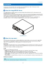
Page 6: ...Introduction 1 Introduction 2...

Page 7: ...ice the imagePRESS Server hardware It is not intended for customer use Information about the printer network remote computers software applications and imagePRESS Server operating system is not includ...

Page 8: ...in the correct tools It is strongly recommended that before you service the imagePRESS Server you carefully read all precautions and notices see Precautions on page 3 Also keep in mind that the most c...

Page 9: ...arpet or vinyl while carrying an electronic component unless it is in an antistatic bag If you remove an electronic component from the printer immediately place it in an antistatic bag Power cable Obs...

Page 10: ...ead screwdriver 0 1 and 2 Phillips head screwdrivers Needlenose pliers imagePRESS Server documentation including the customer media pack and any related service bulletins IMPORTANT Avoid touching magn...

Page 11: ...USING THE IMAGEPRESS SERVER 2 Using the imagePRESS Server 7...

Page 12: ...omatically when the imagePRESS Server is ready for use NOTE If the imagePRESS Server does not start up within 10 minutes see the Startup section of Table 1 Causes and solutions when printer does not p...

Page 13: ...The imagePRESS Server Tools menu 2 USING THE IMAGEPRESS SERVER 8...

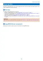
Page 14: ...REPLACING PARTS 3 Replacing Parts 10 Cleaning the imagePRESS Server 36...

Page 15: ...connector panel and LED diagnostic codes on page 11 Accessing the imagePRESS Server To access the imagePRESS Server on page 13 Cable connections Checking imagePRESS Server internal connections on page...

Page 16: ...ling assembly 9 500GB SATA HDD hard disk drive 14 HDD SATA data cable 20 Power supply duct 4 4GB DIMM 15 10 pin power button cable 5 3 3GHz CPU 10 HDD bracket 16 Service board cable 6 Security chip 11...

Page 17: ...x2 8 Duct 4 Printer interface connector 9 Power switch 5 Power connector During startup the imagePRESS Server advances through a standard diagnostic sequence Each diagnostic code flashes rapidly on t...

Page 18: ...Make sure that the imagePRESS Server is not receiving processing or printing any jobs 2 Make sure that the printer is not in use and power off the printer using the main power switch on the front Wait...

Page 19: ...onnector on the motherboard see Motherboard jumpers on page 19 NOTE The imagePRESS Server will not boot up if the HDD data cable is connected to any other SATA connector on the motherboard Faulty data...

Page 20: ...therboard CPU FAN J16 6 Chassis fan cable Chassis fan FRONT FAN connector on motherboard J30 Removing and replacing imagePRESS Server components Before replacing costly components be sure to verify th...

Page 21: ...onent side No Item 1 Printer interface cable connector 2 PCIE x16 connector 3 J351 connector for 10 pin power button cable to motherboard J11 To remove the printer interface board 1 Access and open th...

Page 22: ...of the 10 pin power button cable to J351 connector on the printer interface board Connect the other end to the J11 connector on the motherboard The cable connector is keyed to fit only one way 4 Reas...

Page 23: ...r ADVARSEL Lithiumbatteri Eksplosionsfare ved fejlagtig h ndtering Udskiftning m kun ske med bat teri af samme fabrikat og type Lev r det brugte batteri tilbage til leverand ren VAROITUS Paristo voi r...

Page 24: ...n the URL field of the browser type the IP address or DNS name of the imagePRESS Server and press Enter The IP address is listed under the Network Setup section of the imagePRESS Server Configuration...

Page 25: ...er J4 5 Power button pins J11 11 CPU and cooling assembly MS Mounting screws 6 DIMM A0 12 24 pin power connector J24 NOTE Any connectors not listed are not used Removing the motherboard Before you rem...

Page 26: ...ny one screw completely 2 Lift the edge of the motherboard opposite the connector panel to release the motherboard from the chassis and then gently slide the motherboard out of the chassis NOTE Make s...

Page 27: ...l around the edges of the security chip and pull the chip straight out of the socket Make sure not to put stress on surrounding components IMPORTANT Do not rock the chip from side to side when removin...

Page 28: ...board see To transfer the security chip to the new motherboard on page 22 Install the DIMM s from the old motherboard onto the new motherboard see DIMM on page 17 Install the CPU from the old motherbo...

Page 29: ...ghten the screws doing so could damage traces on the motherboard Now you are ready to replace the remaining motherboard components to complete the motherboard installation To replace motherboard compo...

Page 30: ...CPU socket on motherboard 3 CPU 6 Socket lever To remove a CPU 1 Access and open the imagePRESS Server as described on Accessing the imagePRESS Server on page 13 2 Remove the motherboard components se...

Page 31: ...ew all the way Lift the cooling assembly off the CPU socket and set it aside 1 2 Removing the CPU cooling assembly No Item 1 Screw 1 of 4 2 Loosen each screw to this position 6 Unlock the CPU socket l...

Page 32: ...PU correspond with the two small posts inside the socket Align the two notches properly with the two small posts Align the yellow triangle on the CPU with the flat corner of the socket Do not force th...

Page 33: ...assis 3 Secure the service board to the chassis using the two screws that you removed earlier see above figure 4 Connect the service board cable to the connector on the service board The cable is keye...

Page 34: ...f 4 2 Chassis fan 4 If you are removing the chassis fan in order to replace it with a new one remove the fan guard from the face of the fan see below figure To remove the plastic rivets that secure th...

Page 35: ...connector on the motherboard 4 Align the four holes on the fan with the four holes in the chassis and replace the four rivets that secure the fan to the chassis see below figure Hold the fan firmly a...

Page 36: ...ly and power switch on page 31 2 Place the power supply inside the chassis see To remove the power supply and power switch on page 31 Make sure to fit the power connector through the cutout in the cha...

Page 37: ...the sides and avoid touching the printed circuit boards Allow the HDD to reach room temperature before installation HDD problems may be caused by the following Loose or faulty connection Faulty HDD ba...

Page 38: ...e HDD assembly to release its lower edge from the mounting posts in the chassis and then remove the HDD assembly from the chassis 1 2 Removing the HDD assembly No Item 1 Screw 1 of 2 2 HDD assembly 3...

Page 39: ...ide of the HDD with the holes in the bracket Position the HDD inside the HDD bracket as shown in To remove the HDD on page 32 3 Replace the four screws that attach the bracket to the HDD Make sure tha...

Page 40: ...nel and then lower the cover Replacing the chassis cover 3 Replace the two screws that you removed earlier Tighten the screws to secure the cover to the imagePRESS Server 4 Reinstall the imagePRESS Se...

Page 41: ...Server see Backing up and restoring the system configuration on page 38 When cleaning the imagePRESS Server make sure to move the imagePRESS Server to a place where the stirred dust does not cause any...

Page 42: ...INSTALLING SYSTEM SOFTWARE 4 Installing System Software 38...

Page 43: ...eletes all fonts that the customer has installed on the imagePRESS Server Only resident fonts are restored during system software installation Use Command WorkStation to reinstall additional fonts To...

Page 44: ...talog and choose Export Selected You can Shift click to select sequen tial entries or Ctrl click to select nonsequential entries 2 Navigate to the location on your computer or network where you want t...

Page 45: ...the Restore Completed message appears 8 Click Reboot Using Fiery System Restore Fiery System Restore allows you to create a backup of the imagePRESS Server for quick recovery later when any problem ha...

Page 46: ...tor privileges The default Administrator password is Fiery 1 case sensitive but the site administrator may have changed the password 2 From Server menu select Device Center 3 Click Tools on the left s...

Page 47: ...drive is 32GB if the Create bootable image option in ON You can use a USB flash drive with more than 32GB capacity if the Create bootable image is OFF Create Backup Internal hard drive Select this op...

Page 48: ...rifies the installation requirements NOTE If the computer does not already have Net framework installed click Accept to accept the terms of the license agreement that appears on the screen Wait up to...

Page 49: ...list of any installed options and a record of the customer s current Setup configuration 3 If you are reinstalling the same version of system software back up the current system configuration see Back...

Page 50: ...e imagePRESS Server power switch is in the ON position 17 Power on the printer using the main power switch Allow the imagePRESS Server to start up and reach Idle 00 should appear on the imagePRESS Ser...

Page 51: ...The Configuration pages list all installed options on the imagePRESS Server as well as the customer s current Setup configuration for more information see System software installation reminders on pa...

Page 52: ...TROUBLESHOOTI NG 5 Troubleshooting 48...

Page 53: ...information on several printing problems Where problems occur The imagePRESS Server is a built in print server for the printer Problems may occur in one of the following areas The imagePRESS Server o...

Page 54: ...e connections and verified system components 6 If the problem persists see the code symptom and suggested actions in the following pages 00 When the imagePRESS Server is Idle and in Operational mode t...

Page 55: ...power supply fan you may need to replace a faulty power supply 5 Replace the motherboard 6 Replace the CPU 7 Replace the printer interface board imagePRESS Server starts up but the Fiery screens on th...

Page 56: ...sing or faulty DIMM s DIMM installed in wrong slot or faulty DIMM connections Faulty hard disk drive Overheated or faulty CPU Faulty motherboard 1 Check that the DIMM is installed in the correct slot...

Page 57: ...device may have a corrupted image file or your hard disk drive cannot be accessed 1 Run Windows Disk Error Check on the USB device 2 Prepare the USB device again using the Fiery USB Setup Tool 3 Use...

Page 58: ...tion page dis plays an error on the IPAddress line under Network Setup One of the following Normal behavior System is searching for a nonexistent DHCP server DHCP is enabled by default on the imagePRE...

Page 59: ...n Setup is set to Yes Check for error messages on the imagePRESS Server output Application problem 1 Print a job from a different application to determine if the problem is associated with a particula...

Page 60: ...oblem with the printer Test the printer and service if necessary see the service docu mentation that accompanies the printer Out of calibration or calibration information curves on the active partitio...

Page 61: ...inting problems caused by inappropriate Setup options Application specific printing errors caused by missing or incorrectly installed printer description files Printing to the imagePRESS Server If the...

Page 62: ...time to process If the Data indicator is blinking data is being processed Wait until it is finished Cleaning the imagePRESS Server The accumulation of dust on the fans may cause the following problem...

Page 63: ...ion about the imagePRESS Server You can generate a job error report even if the print job is not in an error state NOTE The error log entries are overwritten after a period of time To ensure the error...

Page 64: ...may exceed the allowed size of the report In this case it may be useful to provide it separately c Optional To include color profiles in the report select Color Profiles Color profiles can be useful t...

Page 65: ...SPECIFICATIONS 6 Specifications 61...

Page 66: ...e following networking features Supports AppleTalk and TCP IP protocols simultaneously RJ 45 Ethernet LAN port for twisted pair 10BaseT 100BaseTX 1000BaseT network connection NOTE The latest user soft...

Page 67: ...2013 Class A EU EN55024 2010 EU AS NZS CISPR 32 2012 AC 2013 Class B EN61000 3 2 2014 EN61000 3 3 2013 EAC Republic of Belarus Republic of Kazakhstan Tajikistan Kyrgyzstan and Armenia TBD CCC China 6...

Page 68: ...INSTALLATION PROCEDURE 7 How to Utilize This Installation Procedure 64 Before Connection 65 Installation Procedure 67 Settings After Installation 75...

Page 69: ...ls in this procedure 1x 1x 1x Install Screw Packaged Item Remove Tighten Loosen 1x Connect Connector Disconnect Install Harness Common for Guides and Clamps Remove 1x 1x Connect Power Cord Disconnect...

Page 70: ...n power switch to determine the registration The IP addresses for communication between the host machine and server are set automatically 1 Enter service mode Level 1 and set the setting value to 3 CO...

Page 71: ...ight Ethernet Cable 300 mm for network connection Cross Ethernet Cable Use 6 of them Binding M4x8 Screw with Toothed Washer 4x Stepped Screw M4x9 2x Europe x 2 USA x 1 Others Including guides Installa...

Page 72: ...stalling the Open I F PCB 1 4x 2 1x 3 2x 4 NOTE Ask the user to keep the removed Face Cover 2x NOTE The removed screws will be used in step 8 5 1x 1x NOTE The removed screws will be used in step 8 7 I...

Page 73: ...ll be used in step 8 7 1x M3x6 8 NOTE Use the screws removed in steps 4 5 and 6 M3x6 6x 1x 2x 9 CAUTION Uniformly push in the Main Controller PCB 2 with both hands until it stops Install the Main Cont...

Page 74: ...perform the work in the order from 1 to 5 in the figure because the connector of the Main Controller PCB 2 may not be connected 2x 11 NOTE The other end of the Interface Cable will be connected in In...

Page 75: ...tep 1 and install it in the direction of the arrow 1x TP M3x6 3 NOTE Hook the Support Plate to the screw left side loosened in step 1 and install it in the direction of the arrow 1x TP M3x6 4 NOTE Tig...

Page 76: ...p 7 7 NOTE Use the 4 screws removed in steps 6 CAUTION Be sure to install it in the correction direction 4x 8 NOTE Hook the imagePRESS Server to the 2 Stepped Screws M4x9 tightened in step 5 to instal...

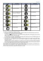
Page 77: ...9 10 11 2x 1x 12 1x Cross Ethernet Cable 1x 7 INSTALLATION PROCEDURE 72...

Page 78: ...ation area of installation Make sure not to leave unused power cord at the site 2x 1x 16 Connect the power plug to the outlet of the host machine 17 Connect the power plug to the outlet of the imagePR...

Page 79: ...20 Turn ON the main power switch of the host machine again 21 Check that the value of the following service mode Level 1 is 462 COPIER OPTION INT FACE CNT TYPE 7 INSTALLATION PROCEDURE 74...

Page 80: ...ay range of the Web browser is extended Settings After Installation 1 Select Fiery from the main menu on the host machine s LCD 2 Select Login to log in as a system administrator Input of password A p...

Page 81: ...ll not be completed unless Save Changes is pressed 5 Press Exit Setup after all settings are completed 6 The confirmation screen will appear and then press Reboot Now 7 The imagePRESS Server will be r...

Page 82: ...ator to connect to the network make settings and output the test print Refer to Configuration and Setup in User s Manual for details of checking work Executing Image Quality Adjustment Execute the ima...

Reviews: