background image

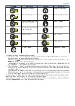
Revision 2.0

MF720 Series

Service Manual

Summary of Contents for MF720 Series

Page 1: ...Revision 2 0 MF720 Series Service Manual...

Page 2: ...long or short period Canon will issue a new edition of this manual The following paragraph does not apply to any countries where such provisions are inconsistent with local law Trademarks The product...

Page 3: ...door and closing the delivery unit door which results in supplying the machine with power 2 In the digital circuits 1 is used to indicate that the voltage level of a given signal is High while 0 is us...

Page 4: ...DF Specifications 10 Wireless LAN Specifications 10 SEND Specifications 11 FAX Specifications 12 Paper types Paper size 13 Name of Parts 14 External View 14 Cross Section View 16 Control Panel 18 2 Te...

Page 5: ...ce 93 Periodically Replaced Parts 94 Durable Parts 95 Periodical Services 96 Cleaning 97 4 Disassembly Assembly 98 List of Parts 99 List of External Internal Cover 99 List of Main Unit 101 List of Mot...

Page 6: ...port Plate 161 Removing the DC Controller PCB 162 Removing the High Voltage Power Supply PCB 163 Removing the Low Voltage Unit 165 Removing the Fixing Sub PCB 166 Removing the Driver PCB 167 Removing...

Page 7: ...Tray Pickup Unit 218 Removing the Secondary Transfer Feed Unit 219 Removing the Delivery Unit 220 Removing the Duplex Feed Unit 221 Removing the Re pickup Guide Unit 222 5 Adjustment 224 Overview 225...

Page 8: ...mode 262 COPIER 264 DISPLAY 264 I O 265 ADJUST 266 FUNCTION 277 OPTION 290 COUTER 295 FEEDER 300 ADJUST 300 FUNCTION 301 FAX 302 Lis of SSSW 302 List of MENU 303 List of NUM 303 Setting of NCU Paramet...

Page 9: ...Safety Precautions Laser Safety 2 How to Handle the Laser Scanner Unit 2 Toner Safety 2 Notes When Handling a Lithium Battery 3 Notes on Assembly Disassembly 3...

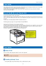
Page 10: ...in the field The label show in the following figure is attached on the laser scanner unit The following warnings are given to comply with Safety Principles EN60950 1 Diese Maschine ist der Klasse 1 de...

Page 11: ...n Notes on Assembly Disassembly Follow the items below to assemble disassemble the device 1 Disconnect the power plug to avoid any potential dangers during assembling disassembling works 2 If not spec...

Page 12: ...Product Overview 1 Product Lineups 5 Product Features 7 Specifications 8 Name of Parts 14...

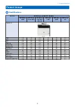
Page 13: ...Yes Yes Yes Yes Fax Yes Yes Yes Yes No No USB Scan Yes Yes Yes Yes Yes Yes Network Scan Yes Yes Yes Yes Yes Yes Wireless LAN Yes Yes Yes No Yes Yes Direct Mode Yes Yes Yes No Yes Yes NFC No Yes Yes N...

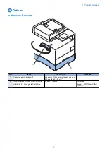
Page 14: ...rks 1 Cassette Feeding Module V1 Expansion of the number of sheets picked up 250 sheets 60 to 90 g m2 2 TELEPHONE 6 KIT Long cord Cool White Addition of phone MF728Cdw HANDSET KIT 3 Long cord Cool Whi...

Page 15: ...or easy customization while maintaining the level of operability Direct Mode supported supported models only Direct communication between the host machine and smartphone tablet PC etc has been realize...

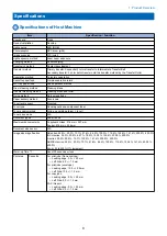
Page 16: ...delivery method Face down Toner level sensor Mounted Toner type Non magnetic one component toner Toner supply method All in one cartridge drum toner Toner save mode N A Document types Sheet book Maxim...

Page 17: ...ted paper Label Postcard Envelope Refer to Paper types Paper size on page 13 Available paper type for MP Tray Plain paper Recycled paper Color paper Thick paper Coated paper Transparency Label Postcar...

Page 18: ...up time is an interval between when the machine is turned ON and when the main screen appears on the display Warm up time may vary depending on the use conditions and environment of the machine 2 The...

Page 19: ...E mail Sending IFAX Reception Transmission Communi cation Pro tocol SMB TCP IP FTP SMTP Data For mat PDF PDF Compact PDF Compact OCR PDF OCR JPEG TIFF PDF PDF Compact PDF Compact OCR PDF OCR JPEG TIF...

Page 20: ...33 6 k bps 9 dBm Modem IC SiliconLabs Si2435 Scanning line density Normal 200 x 100 dpi Fine 200 x 200 dpi Photo 200 x 200 dpi Super fine 200 x 400 dpi Ultra fine 400 x 400 dpi Half tone 256 tones Re...

Page 21: ...3 155 to 165 g m2 A4 210 0 297 0 Yes Yes LTR 215 9 279 4 Yes Yes Coated paper 4 210 to 220 g m2 A4 210 0 297 0 Yes No LTR 215 9 279 4 Yes No Transparency 1 A4 210 0 297 0 Yes No LTR 215 9 279 4 Yes N...

Page 22: ...No Name 1 Feeder 8 Grip 2 Control panel 9 Paper scanner for document from feeder 3 Front cover 10 Delivery tray 4 Paper cassette 11 Manual feed guide 5 Main power switch 12 Copyboard glass 6 Vent hole...

Page 23: ...Rear cover 3 USB port 8 Rating plate 4 Telephone line terminal 9 Vent hole 5 External telephone terminal 10 Power socket Inside 4 3 2 1 5 No Name 1 Y toner cartridge slot 2 M toner cartridge slot 3 C...

Page 24: ...er 11 Primary transfer pad 3 Fixing film unit 12 ITB unit 4 Delivery roller 13 Cassette pickup roller 5 Toner cartridge 14 Cassette separation roller 6 Laser scanner unit 15 Registration roller 7 Phot...

Page 25: ...F Unit 1 2 3 4 5 6 7 8 No Name No Name 1 ADF registration roller 5 Reader unit 2 ADF separation roller 6 ADF delivery roller 3 ADF pickup roller 7 ADF separation pad 4 ADF unit 8 CIS unit 1 Product Ov...

Page 26: ...12 ID key Press after entering the ID and PIN to log on when Department ID Management is enabled After you finish using the machine press this key again to log off 13 Start B W key Press to scan or c...

Page 27: ...Configuration 20 Document Exposure Feeder System 22 Controller System 26 Laser Control System 29 Image Formation System 30 Fixing System 41 Pickup Feed System 44 Embedded RDS 48 Setting Information E...

Page 28: ...to the pressure roller of the fixing assembly check cartridges and units being in place move the developing unit to the home position and clean the ITB When needed color displacement is corrected and...

Page 29: ...to 110 g m2 4 Postcards 5 9 7 ppm 6 1 3 speed mode 1 3 speed Thick paper 3 129 to 163 g m2 2 Coated paper 2 120 to 130 g m2 Coated paper 3 155 to 165 g m2 Coated paper 4 210 to 220 g m2 Transparency L...

Page 30: ...n The speed at which the carriage moves and image processing by the Main Controller PCB Lens CIS Color CIS Number of lines 1 line Number of pixels 5184 pixels as total pixels 5107 pixels as effective...

Page 31: ...nce Position for Printing Only when the original is read from ADF without reduction layout setting 1 on 1 it is printed in center alignment In other cases upper left alignment is applied for printing...

Page 32: ...nal is detected by this mechanism The original length that can be scanned with this equipment is less than 400 mm Passing of the original longer than this results in jam stop The original length is ca...

Page 33: ...How to release Jam Remove the jammed paper and open close the ADF upper cover 2 Technical Explanation 25...

Page 34: ...CBs I O etc and maintain setting values Controls Motor Controls This product uses 3 motors for paper feed and image formation The tables below show motor specifications used in this product Name Symbo...

Page 35: ...rinter engine Noise Filter Fuse FU1101 Fuse FU1102 Fuse FU1201 Fixing Power Supply Rectifying Circuit Main Controller PCB 3 3V 24S_ON 24V Low voltage Power Supply all night Power Switch SW1 DCON_ON 24...

Page 36: ...has passed The auto sleep time has passed The auto sleep time has passed A job is generated completed A job is generated completed The automatic shutdown time has passed The energy saver key is press...

Page 37: ...on signals input by the DC Controller The figure below shows the Laser Scanner Unit schematically Controls Failure detection 1 Scanner Motor failures The rotation does not reach the pre defined value...

Page 38: ...rnal roller The figure below shows the image formation system schematically DC controller High voltage power supply Secondary transfer external roller ITB Cartridge Laser beam ITB cleaning unit Fixing...

Page 39: ...aser beam exposure 9 Drum cleaning 1 Primary charging 4 Primary transfer Transfer block 5 Secondary transfer ITB cleaning block 8 ITB cleaning Registration Pickup Fixing block Delivery 7 Fixing 6 Sepa...

Page 40: ...vely charged toner contacts the photosensitive drum it is deposited on the static latent image due to potential difference between the drum and the developing cylinder Developing blade Developing cyli...

Page 41: ...inator Step 6 Separation Separate the paper from the ITB using paper elasticity and curvature of the ITB drive motor To stabilize the paper delivery and image quality use the static eliminator to deca...

Page 42: ...d from the ITB to the photosensitive drum by the primary transfer pad ITB cleaning brush Sweeper strip ITB cleaning roller ITB DC bias DC bias Partition sheet Positive potential waste toner Negative p...

Page 43: ...ively Primary charging roller car tridge Developing bias DC negative Deposit toner on the static latent image formed on the photosensitive drum Developing cylinder cartridge Blade bias DC negative Adj...

Page 44: ...drum or toner etc The controls listed in the table below are executed when needed to stabilize image quality Control Description D max control Correct values of the primary charging bias and or develo...

Page 45: ...95sec onds Yes Yes Yes Executed after job completionDe tected by the environment sensor 4 After the pre defined counts printed Approx 195sec onds Yes Yes Yes Executed after job completion 5 After the...

Page 46: ...in controller PCB corrects gradation based on the density data to reproduce the ideal half tone images Color displacement control This control is to correct color displacement due to variability of th...

Page 47: ...aximize the service life The DC controller actuates the motor MF8500 Developing motor MF8200 Main motor to switch the direction of the engagement disengagement cam to contact separate the developing c...

Page 48: ...aintains the wider nip to the photosensitive drum to increase transferability The figures below show the difference between the pad transfer method and the conventional roller transfer method schemati...

Page 49: ...supply to the fixing heater The thermistor detects the fixing heater temperature to input the temperature detection signal to the DC controller Note that temperatures at heater ends are not detected i...

Page 50: ...interval extension time seconds 1 2 3 ON 0 Not extended OFF L 270 mm 10 8 6 L 270mm 8 4 2 Fixing temperature control The fixing control circuit controls temperatures of the fixing heater to attain the...

Page 51: ...heater 226 deg C or higher detected at the temperature fuse Failure detection The DC controller determines failures of the fixing assembly under conditions below to stop the fixing heater drive signa...

Page 52: ...Pickup MP Tray Pickup Duplexing Feeding Pickup slot Cassette MP tray Delivery slot Face down tray Automatic 2 sided Available Parts Configuration Duplexing Flapper MP Tray Feed Roler Cassette Pickup...

Page 53: ...er feed Roller separation method This product employs the separation roller method to avoid multi feeding This method prevents multiple sheets from being fed by the driven separation roller The separa...

Page 54: ...eizure jam 7 Internal paper remaining jam 8 Duplex re pickup jam 9 Open door jam Delay jams Pickup delay jam 1 This occurs when the leading edge of the paper is not detected by the registration sensor...

Page 55: ...of the paper but the sensor went off before starting the fixing delivery stationary detection SR8 Internal paper remaining jam When the sensor below detects Paper Sensor before and after Power on Door...

Page 56: ...n between this machine and the UGW using HTTPS SOAP protocol Features and benefits E RDS embedded with a network module in advance can realize a front end processing of e Maintenance imageWARE Remote...

Page 57: ...xy server address Port No for proxy server Information item 4 Is proxy server authentication required If proxy server authentication is required find out the following User name and password required...

Page 58: ...ication results with UGW can be distinguished by referring to the COM LOG By performing the communication test with UGW E RDS acquires schedule information and starts monitoring and meter reads operat...

Page 59: ...nt once every 16 hours The data size of counter information is approx 285 KB Q Will data which failed to be sent due to an error in communication with UGW be resent Ans Data shown below will be resent...

Page 60: ...in E RDS the system wakes up asleep then starts to send the data to the UGW The system also waits for completion of data transmission and let the device to shift to asleep status again However transit...

Page 61: ...tep 4 NO Confirm the details of this machine s IP address and subnet mask settings 4 Confirm DNS connection a Select Settings Registration Preferences Network TCP IP Settings DNS Settings DNS Server A...

Page 62: ...own error is displayed though a communication test COM TEST has done successfully Cause It could be a problem at the UGW side or the network load is temporarily faulty Remedy Try again after a period...

Page 63: ...TTPS communication method Perform and complete a communication test COM TEST 11 8xxx 0201 8xxx 0202 8xxx 0203 8xxx 0204 8xxx 0206 Server schedule is invalid During the communication test there has bee...

Page 64: ...mproper address Check proxy server address port and re enter as needed 25 8xxx 2015 Proxy address resolution error Could not connect to proxy serv er due to name resolution error of proxy address Chec...

Page 65: ...DR is https a01 ugwdevice net ugw agen tif010 33 8xxx 2058 Unknown error SOAP Client fails to obtain SOAP Response Possibility of a problem in UGW or of a temporary problem in the network load Perform...

Page 66: ...ort device DCM support device Settings Registration Service mode Remote UI DCM file iW EMC MC with DCM Plug in DCM support iR ADV DCM file DCM file DCM file DCM file DCM file USB memory device NOTE In...

Page 67: ...menu options Address book 1 Service mode setting values Settings Registration menu Control panel Yes fixed 2 Yes fixed 2 No Remote UI Yes Yes With conditions 3 Service mode Control panel No No Yes Re...

Page 68: ...the firmware version at the time of import differs from that at the time of export predetermined corrective processing may be performed 2 Predetermined corrective processing may be performed 3 If a s...

Page 69: ...rtment ID counter information of ID_1 in the host ma chine is imported ID_1 has not been set in the data to be im ported Not overwritten Information of ID_1 is deleted Department ID information has no...

Page 70: ...imported When an address book is imported the data previously stored is not cleared but overwritten with the records stored in the new address book In other words after the address book is overwritte...

Page 71: ...the service mode settings When the length of the character string exceeds the limit If a character string exceeding the length permitted by the import destination device is registered as for example a...

Page 72: ...de during import or export Although this is not disclosed to users sleep mode internally changes according to the usage conditions of the host machine Sleep mode ranges from energy saver mode where in...

Page 73: ...SB flash drive is not connected a message prompting the user to connect a USB flash drive will appear and the process cannot be executed On the other hand when this function is used export can be exec...

Page 74: ...Mode Remote UI With this model service mode can be used from the Remote UI Setting information can be exported by remote control by following the procedure shown below Since the information can be ou...

Page 75: ...revious procedure into the host machine 1 To the directory directly under the root of the USB flash drive save a setting information file service dcm to be imported 2 Connect a USB memory device to th...

Page 76: ...ing the following service mode setting value to 1 1 Enter service mode and set the following item to 1 COPIER OPTION USER SMD EXPT TNRB SW 0 SCALL SW 0 SCALLCMP 0 PC MODE 0 SMD EXPT 1 NOTE The SMD EXP...

Page 77: ...to export the setting data of the menu options Service Mode Selected and grayed out If this item does not exist perform step 1 again Encryption Password Enter up to 32 alphanumeric characters for the...

Page 78: ...gement Settings Menu Import the service mode setting information file that was exported in the previous procedure 1 Enter service mode and set the following item to 1 COPIER OPTION USER SMD EXPT TNRB...

Page 79: ...4 Click Import Export Import 1 2 2 Technical Explanation 71...

Page 80: ...x to import the Address Book data Address Book PIN If the Address Book PIN is set enter the PIN in the Address Book PIN text box Setting a PIN for Address Book Settings Registration Select the check b...

Page 81: ...ose that are not described here cannot be imported Import coverage Description Case A The same machine Import to the same machine for backup and restoration etc Case B The same model Import to a diffe...

Page 82: ...s Yes End Yes Yes Yes Auto Sleep Time Yes Yes Yes Auto Reset Time Yes Yes Yes Function After Auto Reset Yes Yes Yes Auto Offline Time Yes Yes Yes Common Settings Setting Information Case A Case B Case...

Page 83: ...Terminal ID Yes Yes Yes Print Position Yes Yes Yes Mark Number as Yes Yes Yes Check Dial Tone Before Sending Yes Yes Yes Allow Fax Driver TX Yes Yes Yes Confirm Entered Fax Number Yes Yes Yes Restric...

Page 84: ...Yes Yes Digital Signatures Yes Yes Yes Density Yes Yes Yes Original Orientation Yes Yes Yes Original Type Yes Yes Yes 2 Sided Original Yes Yes Yes Sharpness Yes Yes Yes Data Size Yes Yes Yes Subject Y...

Page 85: ...s Setting Information Case A Case B Case C Prioritize Driver Settings When Printing Yes Yes Yes Multi Purpose Tray Yes Yes Yes Drawer 1 Yes Yes Yes Drawer 2 Yes Yes Yes Copies Yes Yes Yes 2 Sided Prin...

Page 86: ...ution Gradation Text Yes Yes Yes Graphics Yes Yes Yes Image Yes Yes Yes RGB Source Profile Text Yes Yes Yes Graphics Yes Yes Yes Image Yes Yes Yes Output Profile Text Yes Yes Yes Graphics Yes Yes Yes...

Page 87: ...phics Yes Yes Yes Apply to Text Yes Yes Yes Grayscale Conversion Yes Yes Yes Adjustment Maintenance Setting Information Case A Case B Case C Auto Correction Settings Auto Adjust Image Regularly Yes Ye...

Page 88: ...Yes Yes Yes Black White Copy Yes Yes Yes Color Copy Yes Yes Yes Black WhitePrint Yes Yes Yes Color Print Yes Yes Yes Scan Yes Yes Yes Fax Yes Yes Yes Department ID Management Allow Print Jobs with Un...

Page 89: ...No Domain Name Yes No No DNS Dynamic Update Settings Yes Yes Yes DNS Dynamic Update Yes Yes Yes Register Manual Address Yes Yes Yes Register Stateful Address Yes Yes Yes Register Stateless Address Ye...

Page 90: ...Yes Yes Yes Number of Routers to Traverse Yes Yes Yes Notification Interval Yes Yes Yes Google Cloud Print Settings Setting Information Case A Case B Case C Using Google Cloud Print Yes Yes Yes Local...

Page 91: ...SNMPv1 Settings Use SNMPv1 Yes Yes Yes Use Community Name 1 Yes Yes Yes Community Name 1 Yes Yes Yes Use Community Name 2 Yes Yes Yes Community Name 2 Yes Yes Yes MIB Access Permission 1 Yes Yes Yes...

Page 92: ...AirPrint Settings Use AirPrint Yes Yes Yes Latitude Yes No No Longitude Yes No No Mopria Settings Use Mopria Yes Yes Yes Dedicated Port Settings Dedicated Port Settings Yes Yes Yes Waiting Time for Co...

Page 93: ...r the server used for searches Server Name Yes Yes Yes Server Address Yes Yes Yes ition to Start Search Yes Yes Yes Port Number Yes Yes Yes Search Timeout Yes Yes Yes Login Information Yes Yes Yes Use...

Page 94: ...es Yes Yes Use as USB Device Yes Yes Yes Store to USB Memory Yes Yes Yes Memory Media Print On Off Yes Yes Yes Enable Product Extended Survey Program Yes Yes Yes Canon Mobile Scanning ON OFF Yes Yes Y...

Page 95: ...MAI S K2 Yes No No COPIER FUNCTION VIFFNC SMEAR PV Yes No No COPIER FUNCTION VIFFNC FEED IMP Yes No No COPIER FUNCTION VIFFNC FOG PV Yes No No COPIER FUNCTION VIFFNC ICL IMP Yes No No COPIER FUNCTION...

Page 96: ...No No FAX SSSW SW15 Yes No No FAX SSSW SW16 Yes No No FAX SSSW SW17 Yes No No FAX SSSW SW18 Yes No No FAX SSSW SW19 Yes No No FAX SSSW SW20 Yes No No FAX SSSW SW21 Yes No No FAX SSSW SW22 Yes No No F...

Page 97: ...ALTONE 001 Yes No No FAX NCU DIALTONE 002 Yes No No FAX NCU DIALTONE 003 Yes No No FAX NCU DIALTONE 004 Yes No No FAX NCU DIALTONE 005 Yes No No FAX NCU DIALTONE 006 Yes No No FAX NCU DIALTONE 007 Yes...

Page 98: ...8 Yes No No FAX NCU AUTO RX 009 Yes No No FAX NCU CNGDTCT 001 Yes No No FAX NCU CNGDTCT 002 Yes No No FAX NCU CNGDTCT 006 Yes No No FAX NCU CNGDTCT 007 Yes No No FAX NCU CNGDTCT 008 Yes No No FAX NCU...

Page 99: ...NCU SPECIALN 024 Yes No No FAX NCU SPECIALN 025 Yes No No FAX NCU SPECIALN 026 Yes No No FAX NCU SPECIALN 027 Yes No No FAX NCU SPECIALN 030 Yes No No FAX NCU SPECIALN 040 Yes No No FAX NCU SPECIALN...

Page 100: ...A Case B Case C TESTMODE NCU PBXBUSYT 004 Yes No No TESTMODE NCU PBXBUSYT 005 Yes No No TESTMODE NCU PBXBUSYT 006 Yes No No TESTMODE NCU PBXBUSYT 007 Yes No No TESTMODE NCU PBXBUSYT 008 Yes No No FAX...

Page 101: ...Periodical Service 3 Periodically Replaced Parts 94 Durable Parts 95 Periodical Services 96 Cleaning 97...

Page 102: ...Periodically Replaced Parts No periodically replaced parts is set for this product 3 Periodical Service 94...

Page 103: ...Durable Parts No durable parts is set for this product 3 Periodical Service 95...

Page 104: ...Periodical Services No periodical service is set for this product 3 Periodical Service 96...

Page 105: ...beam window glass Clean with lint free paper 3 Multi purpose tray separation pad Clean with lint free paper For heavy soils use alcohol to wipe off with lint free paper 4 Multi purpose tray pickup ro...

Page 106: ...Assembly Procedure 130 Controller System 154 Controller System Disassembly Assembly Procedure 157 Laser Exposure System 184 Laser Exposure System Disassembly Assembly Procedure 185 Image Formation Sy...

Page 107: ...y Tray 9 Right Cover Removing the Right Cover on page 120 10 Control Panel Lower Cover 11 Control Panel Removing the Control Panel Unit on page 169 12 Upper Cover Removing the Upper Cover on page 125...

Page 108: ...ge 123 3 Rear Cover Removing the Rear Cover on page 123 4 Rear Lower Cover Removing the Rear Lower Cover on page 123 5 Power Socket 6 Telephone Line Jack MF728Cdw 727Cdw 726Cdw 725Cdn 7 LAN Port 8 USB...

Page 109: ...ter Replacing the Reader Unit on page 133 3 Control Panel Unit Removing the Control Panel Unit on page 169 4 Duplexing Reverse Drive Unit Removing the Duplex Reverse Drive Unit on page 179 5 Main Driv...

Page 110: ...n page 185 After Replacing the Laser Scanner Unit on page 188 11 ITB Unit Removing the ITB Unit on page 191 12 Delivery Unit Removing the Delivery Unit on page 220 13 Secondary Transfer Feed Unit Remo...

Page 111: ...Drum Motor Main Drive Unit Removing the Drum Motor on page 196 M2 Developing Motor Main Drive Unit Removing the Developing Motor on page 195 M3 Registration Motor Pickup Unit M4 Fixing Motor Product c...

Page 112: ...g Film Unit SP1 Speaker Product configuration MF728Cdw 727Cdw 726Cdw 725Cdn Removing the Speaker MF728Cdw 727Cdw 725Cdn on page 183 SW1 Main Power Switch Product configuration MF727Cdw 726Cdw 725Cdn S...

Page 113: ...er Feeder Unit SR1 Paper Feeder Pre Registration Detection Sensor Pickup Unit SR2 Front Cover Sensor Product configuration SR4 Registration Detection Sensor Pickup Unit SR6 Developing Homeposition Sen...

Page 114: ...r PCB Laser Scanner Unit UN5 Relay PCB Product configuration Removing the Relay PCB on page 168 UN1 3 Main Controller PCB Product configuration Removing the Main Con troller PCB on page 157 Before Rep...

Page 115: ...ing the Fixing Sub PCB on page 166 UN8 Low Voltage Main PCB Low Voltage Power Supply Unit UN9 Low Voltage Sub PCB Low Voltage Power Supply Unit UN10 Duplex Driver PCB Re Pickup Guide Unit UN14 Control...

Page 116: ...7 Fixing Sub PCB J4003 J1301 H220 Fixing heater 230V J311 UN8 Low Voltage Main PCB J4003 J1301 H220 Fixing heater 230V J651 UN7 Fixing Sub PCB J312 UN8 Low Voltage Main PCB J301 UN8 Low Voltage Main P...

Page 117: ...Controller PCB J2009 UN17 Off Hook PCB MF728Cdw 727Cdw 726Cdw 725Cdn J942 UN16 FAX NCU PCB J2001 UN17 Off Hook PCB MF728Cdw 727Cdw 726Cdw 725Cdn 2 5 J3015 J3011 J611 J3001 J3005 J3002 J3003 J3004 J90...

Page 118: ...ion Sensor J163 UN5 Relay PCB J3011 SR4 Registration Detection Sen sor J164 UN5 Relay PCB J3002 SR1 Paper Feeder Pre Registra tion Detection Sensor J165 UN5 Relay PCB J3003 SR12 Pre registration Detec...

Page 119: ...ole noid J156 UN1 DC Controller PCB J654 UN7 Fixing Sub PCB J162 UN5 Relay PCB J3010 SR7 MP Tray Pre Registration De tection Sensor J167 UN5 Relay PCB J3006 SR14 MP Tray Paper Detection Sen sor J167 U...

Page 120: ...ckup Solenoid 4 5 J201 J210 J211 J210 J207 J206 J205 J204 J203 J202 J2001 J213 J2005 J207 J209 J208 J653 J140 J2002 J2003 J206 J209 J208 J2004 J910 J1005 J No Symbol Name Relay connector J No Symbol N...

Page 121: ...enoid J208 UN2 Driver PCB J208 CL1 MP Tray Feeding Clutch J209 UN2 Driver PCB J209 SL1 MP Tray Pickup Solenoid J210 UN2 Driver PCB J210 UN9 Low Voltage Sub PCB J211 UN2 Driver PCB J2002 M1 Drum Motor...

Page 122: ...H802 Main Thermistor Sub Thermistor 1 J150 UN1 DC Controller PCB J707 UN6 Fixing Relay PCB J152 UN1 DC Controller PCB J701 UN10 Duplex Driver PCB J157 UN1 DC Controller PCB J706 UN6 Fixing Relay PCB J...

Page 123: ...ing Relay PCB J301 3 SR9 Fixing Pressure Release Sensor J710 UN6 Fixing Relay PCB J301 4 SR8 Fixing Delivery Sensor J924 UN13 Main Controller PCB J951 UN14 Control Panel NFC PCB J961 UN20 NFC PCB J956...

Page 124: ...ay 9 Right Cover Removing the Right Cover on page 120 10 Control Panel Lower Cover 11 Control Panel Removing the Control Panel Unit on page 169 12 Upper Cover Removing the Upper Cover on page 125 13 U...

Page 125: ...ge 123 3 Rear Cover Removing the Rear Cover on page 123 4 Rear Lower Cover Removing the Rear Lower Cover on page 123 5 Power Socket 6 Telephone Line Jack MF728Cdw 727Cdw 726Cdw 725Cdn 7 LAN Port 8 USB...

Page 126: ...e Front Cover 3 1 DERXW 5 cm 3 2 4 Remove the 2 screws 2 1 2x 5 While pushing the claw 2 of the Left Cover 1 hold the top of the host machine and push the Left Cover directly upward with your finger o...

Page 127: ...1 Fit the hook 1 at the upper right side of the Left Cover to the upper left area 2 of the Upper Cover 1 2 2 Fit the protrusion 1 of Left Cover to the groove 2 of the frame 3 Insert the claw 3 of the...

Page 128: ...move the Right Cover 2 4 Screws 3 3 Hooks 4 3 4 3 3 2 1 4x Installing the Right Cover 1 Fit the 3 hooks 2 of the Right Cover into the holes 3 of the Upper Cover 2 1 3x 3 2 2 While pushing the Right Co...

Page 129: ...Right Cover on page 120 Procerdure 1 Remove the Cassette 2 Open the ADF Unit Reader Unit 1 and the Front Cover 2 3 Draw out the Cartridge Tray 4 Remove the 2 screws 2 4 2 3 1 2x 5 Remove the claw 1 a...

Page 130: ...4 Remove the Right Front Cover Refer to Removing the Right Front Cover on page 121 Procerdure 1 Remove the bushing support 1 2 screws 2 1 2 2x 2 Remove the 2 pins 1 using a screwdriver 1 1 3 While clo...

Page 131: ...er 2 1 Hook 3 1 1 2 3 2x Removing the Rear Cover Procedure 1 Open the Rear Cover 1 2 Close the Duplex Feed Unit 2 1 2 3 Remove the Rear Cover 1 2 screws 2 4 hooks 3 1 3 3 2 2x Removing the Rear Lower...

Page 132: ...ve the 2 claws 2 and 2 bosses 3 1 1x 1x 2 3 2 3 3 Close the Duplex Feed Unit 1 1 4 Move the Rear Lower Cover 1 aside from the A part of the Duplex Reverse Drive Unit 2 5 Hold the Rear Cover Rib Unit 3...

Page 133: ...fer to Removing the Rear Lower Cover on page 123 Procedure 1 Remove the Rear Cover Rib Unit 1 2 bearing holders 2 1 fixing guide 3 1 connector 4 1 3 4 2 1x 1x CAUTION At installation make sure that th...

Page 134: ...fer to Removing the Rear Upper Cover on page 123 Procedure 1 Remove the USB Host PCB Unit 1 1 screw 2 1x 1 1 2 2 Remove 6 screws 1 1 2 2 2 6x 3 Release 2 claws 1 of the Upper Cover with a flat blade s...

Page 135: ...he Toner Cartridge be careful not to damage the Photosensitive Drum Also be sure to block light 1 Open the Front Cover 2 Pull out the Cartridge Tray 1 3 Remove the toner cartridges Y M C Bk 2 2 1 4 Wh...

Page 136: ...ller Unit Removing the ADF Pickup Roller on page 137 5 ADF Separation Roller ADF Roller Unit Removing the ADF Separation Roller on page 138 6 ADF Motor ADF Paper Feeder Unit M721 Removing the ADF Pick...

Page 137: ...t Upper Cover Reader Unit Removing the Reader Unit Upper Cover on page 144 After Replacing the Reader Upper Cover Unit on page 145 12 Scoopup sheet holder Reader Unit Removing the Scoopup sheet holder...

Page 138: ...ge 133 when replacing the ADF Unit and Reader Unit respectively 1 Open the ADF Unit Reader Unit 2 Remove the claw 1 to remove the Reader Shaft Retainer 2 3 While supporting the ADF Unit Reader Unit 3...

Page 139: ...1 A 4 2x Separating the ADF Unit Reader Unit Preparation 1 Remove the Right Cover Refer to Removing the Right Cover on page 120 2 Remove the Left Cover Refer to Removing the Left Cover on page 118 3...

Page 140: ...A 1 2 2 3 After Replacing the ADF Units 1 Adjust the white level in the following service mode and write the final setting values on the service label 1 Enter the values in the following service mode...

Page 141: ...3 White level adj in book mode B W and then execute COPIER FUNCTION CCD DF WLVL4 White level adj in ADF mode B W again 2 ADF geometric adjustment 1 On an image copied using the ADF check the non image...

Page 142: ...d is not shown on the UI so perform the following procedure to judge if the operation was successful or failed B W mode COPIER ADJUST CCD LED BW R Adjustment of LED light up time R at B W reading COPI...

Page 143: ...essful or not COPIER ADJUST CCD DFTAR R Adjustment of shading target value R at ADF reading COPIER ADJUST CCD DFTAR G Adjustment of shading target value G at ADF reading COPIER ADJUST CCD DFTAR B Adju...

Page 144: ...ADF geometric adjustment 1 On an image copied using the ADF check the non image width in the X and Y directions and the expansion contraction in the X direction In the case of E353MGMH perform 2 sided...

Page 145: ...ng match the spring 1 of the ADF Roller Unit to the boss 2 1 2 CAUTION Be sure to put the Sensor Flag 1 above the ADF Roller Unit 2 at installation work 1 1 2 2 Removing the ADF Pickup Roller Preparat...

Page 146: ...of the roller 1 Remove the bushing 1 and the 2 plastic E rings 2 1 2 2 Slide the Roller Shaft 1 to remove the parallel pin 2 and the bushing 3 CAUTION Be careful not to lose the parallel pin 2 at asse...

Page 147: ...late 1 On the Back of the Feed Guide 2 Screws 2 2 Tabs 3 of the Separation Pad Holder 1 2 3 2x 4 Remove the Separation Pad Holder 1 1 CAUTION Be careful not to lose the Spring 1 on the Separation Pad...

Page 148: ...e ADF Front Cover 2 in the direction of the arrow 1 2 3 Lift the ADF Tray 1 until it stops and release the hook 2 to tip the tray into the perpendicular position and remove by pulling upward 1 1 2 1x...

Page 149: ...pper Cover 1 to remove the ADF Pickup Feed Unit 2 1 2 8 Remove the ADF Upper Cover Unit 1 2 bosses 2 1 2 2 Removing the ADF Pickup Motor Preparation 1 Remove the ADF Pickup Feed Unit Refer to Removing...

Page 150: ...ove the Right Cover Refer to Removing the Right Cover on page 120 2 Remove the Left Cover Refer to Removing the Left Cover on page 118 3 Remove the ADF Unit Reader Unit Refer to Removing the ADF Unit...

Page 151: ...eration is judged to be failed turn OFF and then ON the power and execute COPIER FUNCTION INSTALL STRD POS again 2 Adjust the white level in the following service mode and write the final setting valu...

Page 152: ...ailed turn OFF and then ON the power execute COPIER FUNCTION CCD DF WLVL3 White level adj in book mode B W and then execute COPIER FUNCTION CCD DF WLVL4 White level adj in ADF mode B W again Removing...

Page 153: ...uccessful this procedure is completed There is no need to write the value on the service label 4 How to judge whether the operation was successful or failed Whether the operation was successful or fai...

Page 154: ...s not shown on the UI so perform the following procedure to judge if the operation is successful or not COPIER ADJUST CCD DFTAR R Adjustment of shading target value R at ADF reading COPIER ADJUST CCD...

Page 155: ...fter replacing CIS units on page 149 when replacing the CIS unit respectively 1 Pull the Drive Belt 1 to move the CIS Unit 2 2 Loosen the screw 3 and move the Pulley Holder 4 in the direction of the a...

Page 156: ...1 be sure to replace the CIS Spacer 2 together with the CIS Unit 1 included in the pacage of the Service Parts 3 CAUTION When the CIS Spacers are mixed up or lost check the CIS Rank Label 3 to use an...

Page 157: ...IER ADJUST CCD LED BW R Adjustment of LED light up time R at B W reading COPIER ADJUST CCD LED BW G Adjustment of LED light up time G at B W reading COPIER ADJUST CCD LED BW B Adjustment of LED light...

Page 158: ...e setting value on the service label 7 Whether the operation was successful or failed is not shown on the UI so perform the following procedure to judge if the operation is successful or not COPIER AD...

Page 159: ...rtical scanning direction at ADF stream reading back side 2 If you enter adjustment values write the final values on the service label Removing the Reader Scanner Motor Preparation 1 Remove the Right...

Page 160: ...y Holder 4 in the direction of the arrow to remove the Drive Belt 1 4 1 3 1 2 4 Remove the gear 1 1 claw 2 2 1 1x 5 Remove the Shaft Retaining Plate 1 1 screw 2 2 1 1x 6 Move the Sensor Mount 1 1 scre...

Page 161: ...Plate 1 and turn it over 2 screws 2 1 Grounding Plate 3 2 1 3 2x 8 Pass the connector 1 through the hole A 9 Remove the Reader Scanner Motor 3 from the Motor Mounting Plate 2 2 screws 4 4 2 1 A 3 2x 4...

Page 162: ...Removing the FAX PCB MF728Cdw 727Cdw 725Cdw on page 171 4 Main Controller PCB Product Configura tion UN13 Removing the Main Controller PCB on page 157 Before Replacing the Main Controller PCB on page...

Page 163: ...nit Product Con figuration Removing the Duplex Reverse Drive Unit on page 179 13 DC Controller PCB Product Con figuration UN1 Removing the DC Controller PCB on page 162 Before Replacing the DC Con tro...

Page 164: ...ame Main Unit Remarks Reference Adjastment during parts re placement 19 High Voltage Power Supply PCB Product Con figuration UN3 Removing the High Voltage Power Supply PCB on page 163 4 Disassembly As...

Page 165: ...157 Procedure 1 Remove the Wireless LAN PCB 1 1 Screw 2 1 Flat Cable 3 1x 1x 1 2 3 Removing the Main Controller PCB CAUTION When replacing the Main Controller PCB be sure to perform the works to be do...

Page 166: ...igured entered after replacing the PCB The default settings shown on the service label 1 The machine s serial number Settings Registration System Settings Device Information Location 1 4 Enter service...

Page 167: ...tting of destination paper size group 1 COPIER OPTION BODY LOCALE to set destination groups Settings 1 Japan 2 North America 3 Korea 4 China 5 Taiwan 6 Europe 7 Asia 8 Oceania 2 COPIER OPTION BODY SIZ...

Page 168: ...g COPIER ADJUST CCD LED BW B Adjustment of LED light up time B at B W reading Check the foregoing values If all of them remain 1 000 the operation result is judged to be failed If the operation result...

Page 169: ...de 2 Refer to the following items in the Startup Guide and install the drivers which were uninstalled In case of network connection Installing via Network Connection In case of USB connection Installi...

Page 170: ...DC Controller PCB Refer to After Replacing the DC Controller PCB on page 163 Before Replacing the DC Controller PCB 1 Execute the following service mode to restore the DC Controller setting values th...

Page 171: ...tment Maintenance Print Color Displacement Correction Menu Adjustment Maintenance Auto Gradation Correction Quick Correction 5 Turn OFF and then ON the power Removing the High Voltage Power Supply PCB...

Page 172: ...1 1 6x 1x 5 Remove the High Voltage Power Supply PCB 1 9 claws 2 2 1 2 2 2 10x CAUTION When installing the High voltage Power PCB 1 to the host machine make sure that the contact spring 3 is connecte...

Page 173: ...er PCB Refer to Removing the Main Controller PCB on page 157 6 Removing the Main Controller Support Plate Refer to Removing the Main Controller Support Plate on page 161 7 Removing the Fixing Fixing P...

Page 174: ...ing the Main Controller PCB on page 157 5 Removing the Main Controller Support Plate Refer to Removing the Main Controller Support Plate on page 161 6 Removing the FAX PCB MF728Cdw 727Cdw 725Cdn only...

Page 175: ...on page 130 5 Removing the Rear Upper Cover Refer to Removing the Rear Upper Cover on page 123 6 Removing the Upper Cover Refer to Removing the Upper Cover on page 125 7 Removing the Wireless LAN PCB...

Page 176: ...oving the Rear Upper Cover Refer to Removing the Rear Upper Cover on page 123 4 Removing the ADF Unit Reader Unit Refer to Removing the ADF Unit Reader Unit on page 130 5 Removing the Right Front Cove...

Page 177: ...claw 1 to remove the Reader Shaft Retainer 2 2 While supporting the ADF Unit Copyboard Reader Unit 3 remove the Reader Support Shaft 4 3 Bring down the Reader Support Shaft 4 to close the ADF Unit Cop...

Page 178: ...trol Panel Unit 1 and disconnect the Faston Connector 2 11 Claws 3 1 3 3 3 2 3 11x 1x CAUTION Do not touch the IC part A of the LCD Flat Cable 1 A 7 Turn the Control Panel Unit 1 over and disconnect t...

Page 179: ...able 1 A 1 Remove the NFC PCB 1 1 Connector 2 1 Screws 3 1 1x 1x 3 2 Removing the FAX PCB MF728Cdw 727Cdw 725Cdw Preparation 1 Removing the Right Cover Refer to Removing the Right Cover on page 120 2...

Page 180: ...r to Removing the Upper Cover on page 125 7 Removing the Wireless LAN PCB MF728Cdw 727Cdw 724Cdw only Refer to Removing the Wireless LAN PCB MF728Cdw 727Cdw 724Cdw on page 157 8 Removing the Main Cont...

Page 181: ...page 172 Procedure 1 Remove the Harness Guide and plate 1 1 Connector 2 1 Harness Guide A 2 Screws 3 1 1 2 3 3 A 2x 1x 2 Free the harness 1 4 Harness Guides A A 1 4x 3 Free the harness 1 from the gui...

Page 182: ...ee the harness 1 extruding out of the rear side B and C of the machine from the Harness Guide A 1 1 1 1 1 A C B 1x 6 Remove the Harness Guide and Power Auxiliary Plate 1 2 Screws 2 1 1 1 2x 4 Disassem...

Page 183: ...e vicinity be sure to install the Special Flat head Screw 2 in the location it was in before removal 2 4 3 1 5 5 6 3 4 6x CAUTION When installing be sure to place the A part of DC Controller Support P...

Page 184: ...ng Plate 1 3 Screws 2 1 2 2 3x 11 Remove the wire harness guide 1 2 Claws 2 1 Hook 3 1 2 2 3 2x 12 Remove the sheet 1 3 Hooks 2 2 2 1 13 Free the harness 1 and 2 from the Harness Guide A and B 1 2 B 2...

Page 185: ...2 and remove the wire harness guide 2 in the arrow direction 1 Claw 3 2 Fixing Guides 4 4 4 3 1 2 2x 1x CAUTION When removing the Main Drive Unit the Contact Spring 1 may come off so be sure not to lo...

Page 186: ...Front Door Arm 2 is pulled out 1 link 3 is on the right side 1 1 1 1 2 3 NOTE The Main Drive Unit side needs to be in the following condition when installing the Main Drive Unit The directions of the...

Page 187: ...Drive Unit with the joint 2 of the host machine Fit the hole 3 of the link with the shaft 4 of the host machine Fit the hole 5 of the Front Door Arm with the shaft 6 of the host machine 1 5 3 2 4 6 R...

Page 188: ...harnesses 1 at the bottom of the Guide A when installing A 1 A 1 2 Open 1 the Duplex Feed Unit and remove the Duplex Reverse Drive Unit 2 3 screws 3 3 1 2 3x Removing the Fixing Fixing Power Supply Co...

Page 189: ...Support Plate on page 161 Procedure 1 Remove the Cooling Fan Unit 1 1 Connector 2 2 Screws 3 2 Harness Guides A 1 Harness Guide B 3 3 1 B A 2 2x 1x 1x 2 Remove the Fixing Fixing Power Supply Cooling...

Page 190: ...r on page 123 5 Removing the Rear Lower Cover Refer to Removing the Rear Lower Cover on page 123 6 Removing the Rear Cover Rib Unit Refer to Removing the Rear Cover Rib Unit on page 125 Procedure 1 Re...

Page 191: ...Make sure that the fan label 2 faces to the Duplex Feeding Unit side 1 2 Removing the Speaker MF728Cdw 727Cdw 725Cdn Preparation 1 Removing the Right Cover Refer to Removing the Right Cover on page 12...

Page 192: ...ts Name Main Unit Remarks Reference Adjastment during parts replace ment 1 Laser Scanner Unit Product Config uration Removing the Laser Scanner Unit on page 185 After Replacing the Laser Scanner Unit...

Page 193: ...ar Lower Cover on page 123 9 Removing the Rear Cover Rib Unit Refer to Removing the Rear Cover Rib Unit on page 125 10 Removing the Duplex Printing Reverse Drive Unit Refer to Removing the Duplex Reve...

Page 194: ...ee the harness 2 and the Flat Cable 3 2 Flat Cables 4 5 Connectors 5 3 Fixation Guides 6 6 Claws 7 7 6 5 5 1 3 4 2 5 5 7 7 7 6x 2x 5x 3x 3 Remove the Harness Guide 1 1 Screw 2 1 Spring 3 2 Hooks 4 1 4...

Page 195: ...ng 2 on the flag 3 of the Laser Scanner Unit when installing 1 A 2 3 4 Remove the Upper Front Supporting Plate 1 4 screws 2 1 2 2 4x 5 Remove the Scanner Fixing Spring 1 on the right side from 1 hook...

Page 196: ...vertical scanning irradiation position1 C COPIER ADJUST SCNR SUB S K1 Laser output correction value vertical scanning irradiation position1 K COPIER ADJUST SCNR SUB S Y2 Laser output correction value...

Page 197: ...canning irradiation position2 Y COPIER ADJUST SCNR MAI S M2 Laser output correction value horizontal scanning irradiation position2 M COPIER ADJUST SCNR MAI S C2 Laser output correction value horizont...

Page 198: ...Drive Unit M1 Removing the Drum Motor on page 196 3 Developing Motor Main Drive Unit M2 Removing the Developing Motor on page 195 4 Patch Density Registration Sensor Unit Product Configuration Removin...

Page 199: ...y Registration Sensor Unit 1 toward the front 2 Screws 2 2 Bosses 3 2 Protrusions 4 1 1 4 3 3 2 2 2x When it is difficult to pull out the Patch Density Registration Sensor Unit toward the front and th...

Page 200: ...ation Sensor Unit 2 at the lower side and the frame 3 at the upper side when installing removing 1 3 2 4 Open the Rear Cover 1 5 Hold the 2 parts A at the front side of the ITB Unit to tilt the ITB Un...

Page 201: ...Unit Reader Unit on page 130 5 Removing the Right Front Cover Refer to Removing the Right Front Cover on page 121 6 Removing the Upper Cover Refer to Removing the Upper Cover on page 125 7 Removing t...

Page 202: ...the 2 protrusions 1 A 1 1 5 Put the connector 1 through the hole A and remove the Patch Density Registration Patch Sensor Unit 2 1 2 A NOTE When it is difficult to put the connector 1 of the Patch Den...

Page 203: ...g the ADF Unit Reader Unit Refer to Removing the ADF Unit Reader Unit on page 130 5 Removing the Rear Upper Cover Refer to Removing the Rear Upper Cover on page 123 6 Removing the Upper Cover Refer to...

Page 204: ...age 118 3 Removing the Right Front Cover Refer to Removing the Right Front Cover on page 121 4 Removing the ADF Unit Reader Unit Refer to Removing the ADF Unit Reader Unit on page 130 5 Removing the R...

Page 205: ...re harness guide 1 1 claw 2 2 hooks 3 2 3 3 1 1x 3 Remove the Drum Motor 1 3 screws 2 2 1 3x CAUTION Be sure to identify the Drum Motor and the Developing Motor by the difference in gears Gear 1 of th...

Page 206: ...ansfer Outer Roller is included in Secondary Transfer FeedUnit so when replacing the Secondary Transfer Outer Roller be sure toreplace the Secondary Transfer Feed Unit itself Refer to Removing the Sec...

Page 207: ...n figuration Removing the Fixing Assembly on page 200 2 Fixing Motor Unit Product Con figuration M4 Removing the Fixing Motor Unit on page 205 3 Fixing Pressure Roller Fixing Assem bly Removing the Fi...

Page 208: ...fer to Removing the Rear Lower Cover on page 123 6 Removing the Rear Cover Rib Unit Refer to Removing the Rear Cover Rib Unit on page 125 7 Removing the Duplex Printing Reverse Drive Unit Refer to Rem...

Page 209: ...20 2 Removing the Left Cover Refer to Removing the Left Cover on page 118 3 Removing the Rear Upper Cover Refer to Removing the Rear Upper Cover on page 123 4 Removing the Rear Cover Refer to Removing...

Page 210: ...Bosses 4 2 Protrusions 5 5 2 3 3 5 2 3 3 4 4 4 1 1 2 Remove the gear 1 2 Parallel Pins 2 E Ring 3 cam 4 and bushing 5 1 Claws 6 6 1 5 2 2 3 4 1x CAUTION At installation be sure to match the direction...

Page 211: ...f the Sensor Flag 2 1 2 CAUTION Be sure to prevent the guide 1 from hitting against the Fixing Film Unit 2 when installing removing 1 2 4 While securing the harness 1 to the guide A remove the harness...

Page 212: ...Harness Guide A C and D A D C 1 2 1x 8 Remove the harness 1 and the guide 2 1 Claws 3 2 Bosses 4 3 4 2 1 1 4 2 1x CAUTION When installing removing the Fixing Film Unit be sure not to touch the Fixing...

Page 213: ...Removing the Fixing Assembly Refer to Removing the Fixing Assembly on page 200 9 Removing the Fixing Film Unit Refer to Removing the Fixing Film Unit on page 201 Procedure CAUTION Be sure not to touc...

Page 214: ...g the Fixing Sub PCB Refer to Removing the Fixing Sub PCB on page 166 Procedure 1 Free the harness 1 to remove the Sub Power Supply PCB Holder 2 2 Claws 3 2 Bosses 4 3 1 4 4 2 2x 2x 2 Remove the Fixin...

Page 215: ...CAUTION In installation put the edge of the spring 1 and the projection 2 of the gear into the hole on the sheet metal 2 1 4 Disassembly Assembly 207...

Page 216: ...page 212 5 MP Paper Pickup Unit Product Configuration Removing the MP Tray Pickup Unit on page 218 6 MP Paper Pickup Roller MP Paper Pickup Roller Unit Removing the MP Tray Pickup Roller on page 211 7...

Page 217: ...st machine remove toner cartridges Y M C Bk 6 Place a host machine 1 as the Left Cover faces to the bottom CAUTION When laying down the main body be sure to secure the ADF Unit with tape to prevent fr...

Page 218: ...e 2 Make the Left Cover face down and place the host machine 1 CAUTION When laying down the main body be sure to secure the ADF Unit with tape to prevent from opening In case that the ADF Unit is not...

Page 219: ...tch 2 Execute the following items in Service mode COPIER FUNCTION VIFFNC FD R CHG 3 The Multi purpose Tray Pickup Roller rotates to the replacement position 4 Remove the cassette 5 Lower the Multi pur...

Page 220: ...e Rear Upper Cover Refer to Removing the Rear Upper Cover on page 123 6 Removing the Upper Cover Refer to Removing the Upper Cover on page 125 7 Removing the Wireless LAN PCB MF728Cdw 727Cdw 724Cdw on...

Page 221: ...Unit Refer to Removing the ADF Unit Reader Unit on page 130 5 Removing the Rear Upper Cover Refer to Removing the Rear Upper Cover on page 123 6 Removing the Upper Cover Refer to Removing the Upper Co...

Page 222: ...sure not to touch the Secondary Transfer Roller 1 and the ITB 2 1 2 1 Remove the wire harness 2 from the wire harness guide 1 8 connectors 3 10 fixing guides 4 3 3 4 4 4 4 4 2 4 1 3 1x 9x 4x 3x 4 Dis...

Page 223: ...guide 2 to align the hook 4 with the hole on the arm 3 and remove the arm 3 3 hooks 5 1 5 3 4 2 2x CAUTION 1 When tilting the host machine remove the Toner Cartridge Y M C Bk beforehand 2 For protect...

Page 224: ...the machine as the Left Cover faces to the bottom 1 6 Remove the 2 stoppers 2 2 Bosses 3 2 3 2 3 1 7 Remove the 2 arms 1 and the 2 springs 2 2 Shafts 3 5 Hooks 4 1 1 2 2 3 3 4 4 4 4 4 Disassembly Asse...

Page 225: ...sure not to touch the Pickup Roller 1 and the Secondary Transfer Roller 2 1 2 1 Open the Rear Cover 1 Put the harness 2 through the hole A of the Side Plate and Install the Pickup Unit 3 to the host...

Page 226: ...p Unit Procedure CAUTION When tilting the host machine make sure to remove the Toner Cartridge Y M C Bk beforehand 1 Remove the cassette 2 Make the Left Cover face down and place the host machine 1 CA...

Page 227: ...2 2 1 5 Push a flat blade screwdriver to the stopper 1 and remove the MP Tray Pickup Unit 2 in the direction of the arrow 2 2 1 Removing the Secondary Transfer Feed Unit CAUTION Secondary Transfer Out...

Page 228: ...Cover Refer to Removing the Rear Cover on page 123 5 Removing the Rear Lower Cover Refer to Removing the Rear Lower Cover on page 123 6 Removing the Rear Cover Rib Unit Refer to Removing the Rear Cov...

Page 229: ...Refer to Removing the Right Cover on page 120 2 Removing the Left Cover Refer to Removing the Left Cover on page 118 3 Removing the Secondary Transfer Feed Unit Refer to Removing the Secondary Transf...

Page 230: ...emoving the Left Cover on page 118 3 Removing the Secondary Transfer Feed Unit Refer to Removing the Secondary Transfer Feed Unit on page 219 4 Removing the Rear Upper Cover Refer to Removing the Rear...

Page 231: ...ure 1 Remove the Re pickup Guide Unit 1 3 connectors 2 4 screws 3 2 3 3 3 3 1 4x 3x CAUTION Be sure to insert the 2 harnesses 1 at the bottom of the Guide A when installing A 1 A 1 4 Disassembly Assem...

Page 232: ...Adjustment 5 Overview 225 Adjustment at Parts Replacement 226...

Page 233: ...lacing the Reader Unit on page 227 Scoopup Sheet Holder After Replacing the Scoopup Sheet Holder on page 233 Reader Upper Cover Unit After Replacing the Reader Upper Cover Unit on page 230 CIS Units A...

Page 234: ...he foregoing values and if all the values remain the same with those you entered the operation result is judged to be failed 8 If the operation result is failed turn OFF and then ON the power execute...

Page 235: ...W PLT Z The last four digits of the value on the label 3 Return the Scoop up Sheet to its original position 4 AGC adjustment 1 Entering a provisional value Change the foregoing values to 1 000 COPIER...

Page 236: ...he following procedure to judge if the operation was successful or failed Check the value of COPIER ADJUST ADJ XY STRD POS Adjustment of reading position at ADF stream reading If it remains 20 the ope...

Page 237: ...following service mode items Enter the values of OFST P Y OFST P M OFST P C and OFST P K in the following service mode and write the entered values on the service label COPIER ADJUST PASCAL OFST P Y...

Page 238: ...Adjust the white level in the following service mode COPIER FUNCTION CCD BW AGC CIS intensity adjustment in ADF B W COPIER FUNCTION CCD CL AGC CIS intensity adjustment in ADF color 3 If the operation...

Page 239: ...CD DF WLVL3 White level adj in book mode B W 5 Place the same blank paper on the ADF again and execute COPIER FUNCTION CCD DF WLVL4 White level adj in ADF mode B W 6 If the operation was successful wr...

Page 240: ...LED CL G Adjustment of LED light up time G at color reading COPIER ADJUST CCD LED CL B Adjustment of LED light up time B at color reading Check the foregoing values If all of them remain 1 200 the op...

Page 241: ...adj in ADF mode B W again 4 Copyboard geometric adjustment Enter the values shown on the label that comes with the part in the following service mode items COPIER ADJUST ADJ XY ADJ X Adj of img pstn...

Page 242: ...DF WLVL4 White level adj in ADF mode B W 6 If the operation was successful write the setting value on the service label 7 Whether the operation was successful or failed is not shown on the UI so perf...

Page 243: ...nformation Export Import Function DCM on page 58 export the following information User data the settings of the Settings Registration menu and the address book Service mode setting information 3 Write...

Page 244: ...mode data the default value for each destination is set Job IDs Log data Dates 2 Execute the following service mode to clear the reader DF related factory adjustment values COPIER FUNCTION CLEAR R CO...

Page 245: ...mode to back up the DC Controller setting values COPIER FUNCTION VIFFNC STOR DCN 3 The initial installation mode will be activated by turning OFF and then ON the power Configure the following settings...

Page 246: ...u on the LUI of the machine it is necessary to execute this process 8 Setting of automatic shutdown menu display Set 1 for automatic shutdown menu display in service mode default 0 COPIER OPTION BODY...

Page 247: ...position2 C COPIER ADJUST SCNR SUB S K2 Laser output correction value vertical scanning irradiation position2 K COPIER ADJUST SCNR MAI S Y0 Laser output correction value horizontal scanning irradiatio...

Page 248: ...Troubleshooting 6 Test Print 241 Trouble shooting items 243 Version Upgrade 244 Debug Log 248...

Page 249: ...to Removing the Right Cover on page 120 2 Turn on the device on standby to press the test print switch 1 on the right side of the device 3 The engine test chart is printed in the horizontal line patt...

Page 250: ...TESTMODE PRINT COUNT Enter the number of sheets to output Settings 1 99 1 TESTMODE PRINT PHASE Select 1 side or 2 side 2 side selected for 1 side devices is invalid Settings 0 1 side 1 2 side 0 TESTM...

Page 251: ...adjust nip width Improper nip width however may cause faulty fixing To avoid potential faults confirm the nip width of the fixing assembly in the following steps 1 Output a A4 sheet printed in solid b...

Page 252: ...B Some UST versions meet less numbers of firmware than those listed above Preparation System Requirements OS one of the following Microsoft Windows Server 2003 Microsoft Windows Vista Microsoft Window...

Page 253: ...pgrade firmware is shown on the display Select Yes 5 Press OK to automatically restart the device DOWNLOAD MODE is shown on the display 6 Wait for the motor of the host machine to stop NOTE Press STOP...

Page 254: ...message to start download 7 Click OK button when download is completed 8 Turn off and on the power to restart the device 9 Output the spec report from Service mode to confirm if the firmware version...

Page 255: ...to connect the device to the external network This is applicable either in a wired LAN environment or a wireless LAN environment Messages The message displayed on the device operation panel is as fol...

Page 256: ...ction of debug log is not necessary Conditions for collecting logs Conditions for not being able to collect logs In the following cases the procedure for obtaining logs is not required because logs ca...

Page 257: ...er it is necessary to gain approval from the user before collecting it Also the collected file needs to be handled in the same manner as that for user data necessary for reproduction NOTE The followin...

Page 258: ...Error Jam Alarm 7 Outline 251 Error Codes 252 Jam Code 257...

Page 259: ...nce this product does not collect logs for jams and alarms no alarm code is shown Code type Description Reference Error code Shown for any problem occurred in the de vice List of error codes Jam code...

Page 260: ...g Assembly 3 Replace the DC Controller PCB E003 0001 Title Abnormal low temperature of Fixing Assembly caused by Sub Thermistor Description It was detected that the temperature of the Sub Thermistor o...

Page 261: ...The cycle of the Developing Motor speed detection signal did not become the specified cycle since the Developing Motor started to be driven Remedy 1 Check the connector between the Developing Motor an...

Page 262: ...ler PCB 4 Replace the Toner Cartridge E196 0000 Title DCON ROM error Description The ROM of the DC Controller PCB failed to be updated Remedy 1 Install the set of the controller firmware 2 Replace the...

Page 263: ...medy 1 Check the connector connection between the Engine Controller PCB and the Main Con troller PCB 2 Install the set of the controller firmware 3 Replace the Main Controller PCB 4 Replace the Engine...

Page 264: ...nt correction could not be obtained Remedy 1 Install the DC Controller firmware 2 Install the set of the controller firmware 3 Replace the DC Controller PCB E766 9000 Title Scanner power state error f...

Page 265: ...Sensor PS702 PS703 03 0104 Delay Registration Detection Sensor SR4 03 0105 MP Tray Pre Registration Detection Sensor SR7 03 010C Fixing Delivery Sensor SR8 03 014C Delivery Full Sensor SR15 03 0184 R...

Page 266: ...livery Sensor SR8 03 02A4 Duplex revers Registration Detection Sensor SR4 03 1014 Power ON Registration Detection Sensor Fixing Delivery Sensor Fixing Loop Sensor MP Tray Pre Registration Detection Se...

Page 267: ...Service Mode 8 Overview 260 COPIER 264 FEEDER 300 FAX 302 TESTMODE 308...

Page 268: ...the main controller PCBs DC controller PCBs or clearing RAM tuned ADJUST and OPTION values are reset to defaults Each service technician should adjust these values in field and ensure to write values...

Page 269: ...category screen Return key Category Sub category selection screen Scroll the screen Flick the screen 63 2 867 81 7 21 237 21 Go to Item selection screen Tap the screen Go to Initial screen Return key...

Page 270: ...in the following cases Service mode is not used on LUI There is no user who has been logged in to the remote UI service mode this function Remote UI is enabled in the setting of LUI Setting Menu Syst...

Page 271: ...TE After login if you close the browser without logout it is recognized that you have been logged in Therefore in order to log in to service mode again you must wait for a certain period of time 3 min...

Page 272: ...DEMODATA Title Demo print data version Details To display the version of demo print data Since this machine does not have demo print function FF FF is displayed Use case When upgrading the firmware Ad...

Page 273: ...e mode COPIER ADJUST CCD DFTAR G TARGET R Title Shading target value R Details To display the shading target value of Red Continuous display of 128 minimum or 384 maximum is considered a failure of th...

Page 274: ...orizontal scanning direction Details To adjust the image reading start position in the horizontal scanning direction at copyboard reading When replacing the Main Controller PCB enter the value of serv...

Page 275: ...method Enter the setting value switch negative positive by key and press Apply key Caution After the setting value is changed write the changed value in the service label Display adj set range 20 to...

Page 276: ...to 255 Default value 8 Related service mode COPIER FUNCTION CCD CL AGC OFST CL2 Title Adjustment of CIS Front at color reading Details To adjust the offset of the CIS Front when reading color origina...

Page 277: ...2 Default value 1000 Related service mode COPIER FUNCTION CCD BW AGC LED CL R Title Adjustment of LED light up time R at color reading Details To adjust the red color LED lighting time when reading co...

Page 278: ...djust the offset of C color test print reading signal at Auto Adjust Gradation Full Adjust When replacing the Main Controller PCB clearing the RAM data enter the value of service label As the greater...

Page 279: ...g value of Bk color developing bias Use case When an image failure occurs Adj set operate method Enter the setting value switch negative positive by key and press Apply key Display adj set range 5 to...

Page 280: ...method Enter the setting value switch negative positive by key and press Apply key Display adj set range 5 to 5 Default value 0 Related service mode COPIER ADJUST VIFADJ TR2BK HV TR2BK HV Title Adjus...

Page 281: ...3 to 1023 Default value 0 SUB S K0 Title Adjustment of emitting position 1 Bk in the vertical scanning direction Details To adjust the Bk color emitting position 1 in the vertical scanning position Us...

Page 282: ...er Scanner Unit enter the value written on the label included in the package of the Laser Scanner Unit Adj set operate method Enter the setting value switch negative positive by key and press Apply ke...

Page 283: ...r scan time 2 in the horizontal scanning direction Use case When replacing the Laser Scanner Unit enter the value written on the label included in the package of the Laser Scanner Unit Adj set operate...

Page 284: ...ing value switch negative positive by key and press Apply key Display adj set range 127 to 127 Default value 0 MAI S K2 Title Adjustment of scan time 3 Bk in the horizontal scanning direction Details...

Page 285: ...to execute this item after DF WLVL1 Related service mode COPIER ADJUST CCD DFTAR R COPIER ADJUST CCD DFTAR G COPIER ADJUST CCD DFTAR B COPIER FUNCTION CCD DF WLVL1 DF WLVL3 Title White level adj in b...

Page 286: ...hen replacing the CIS Unit Related service mode COPIER FUNCTION CCD CL AGC COPIER ADJUST CCD OFST BW0 COPIER ADJUST CCD OFST BW1 COPIER ADJUST CCD OFST BW2 COPIER ADJUST CCD GAIN BW0 COPIER ADJUST CCD...

Page 287: ...CLEAR CARD clear the information on connection of the Copy Card Reader F1 4 Execute COPIER FUNCTION CLEAR E719 CLR 5 Turn OFF the main power 6 Remove the Card Reader F1 7 Turn ON the main power Relat...

Page 288: ...em data list system dump list Details To execute report output of the system data list and the system dump list System data list The service software switches and parameters used in FAX function Syste...

Page 289: ...dj set operate method Select the item and then press Yes key Fax model only SYSTEM COPIER FUNCTION SYSTEM Item Description PANEL UP Title Download from USB memory PANEL Details To perform downloading...

Page 290: ...pply key Display adj set range 0 to 1 0 OFF 1 ON Default value 0 FEED IMP Title Execution of pickup jam reduction mode Details When using paper with which double feed is more likely to occur pickup op...

Page 291: ...en backup data which has been left for a long period of time is restored it is overwritten with the old setting data and the new data is deleted Related service mode COPIER FUNCTION SYSTEM RSTR DCN RS...

Page 292: ...Default value 0 SPL14682 Title Execution of image fogging prevention mode 1 Details To change the developing bias Use case When toner is lightly transferred to the white area in case of printing an i...

Page 293: ...range 0 to 1 0 OFF 1 ON Default value 0 SPL37510 Title ON OFF of ITB cleaning at paper size mismatch Details Normally when paper other than that of the specified size is fed ITB cleaning is executed...

Page 294: ...j set range 0 to 20 Unit 0 1 mm Default value 0 Related service mode COPIER FUNCTION SPLMAN SPL68677 SPL93822 Title Setting of department ID count all clear Details To set whether to disable clearing...

Page 295: ...leep Time Use case When changing the setting time to shift to auto sleep mode Adj set operate method 1 Enter the setting value and then press Apply key 2 Turn OFF ON the main power switch Display adj...

Page 296: ...ust the ADF scanning position automatically Use case At ADF installation uninstallation Adj set operate method 1 Set a paper for stream reading position adjustment and then close the ADF 2 Select the...

Page 297: ...COM RSLT COPIER FUNCTION INSTALL COM LOG Supplement memo Embedded RDS Function to send device information such as the device counter failure and con sumables to UGW via SOAP protocol UGW Universal Ga...

Page 298: ...cuted when changing the location the setting informa tion of user mode service mode etc is initialized The setting information of this item is not initialized Display adj set range 1 to 10 1 Japan 2 N...

Page 299: ...ver dependent 1 Not used Default value 0 Supplement memo SMTP authentication Protocol in which user authentication function is added to SMTP which is the pro tocol to be used for e mail transmission A...

Page 300: ...te method 1 Enter the setting value and then press Apply key 2 Turn OFF ON the main power switch Display adj set range 0 to 2 0 Password is not required 1 Password for service engineer is required 2 P...

Page 301: ...Apply key Display adj set range 100 to 200 Default value 100 DSPL SW COPIER OPTION DSPL SW Item Description CRGLW LV Title SW to display hide the setting menu user mode of toner low threshold value D...

Page 302: ...atibility with existing machine regarding image process or print specification with PS print Setting of a value other than the setting values means that multiple settings are combined Ex ample 7 1 2 4...

Page 303: ...ince the serial number of the device is not succeeded Use case When replacing the Main Controller PCB Adj set operate method 1 Write down the current data in System Settings Device Information Locatio...

Page 304: ...OPIER COUNTER TOTAL TTL PDL PRT Title PDL print counter Details To count up when the PDL print is delivered outside the machine 2 sided printout is stacked The counter is advanced regardless of the or...

Page 305: ...advanced by delivery in service mode Display adj set range 0 to 99999999 Unit Number of times Default value 0 FAX model only PICK UP COPIER COUNTER PICK UP Item Description C1 Title Cassette 1 pickup...

Page 306: ...jam counter Details To count up the number of total jam occurrences Use case When checking the total jam counter of printer Display adj set range 0 to 99999999 Unit Number of times Default value 0 FE...

Page 307: ...nt up the number of sheets to be fed regardless of 1 sided 2 sided mode Accumulated counter value Use case When checking the consumption level of parts replacing the parts Adj set operate method To cl...

Page 308: ...ey and press Apply key Display adj set range 200 to 200 Unit 0 01 Default value 0 DOCST2 Title Fine adjustment of VSYNC timing at ADF reading back side Details To make a fine adjustment of the VSYNC t...

Page 309: ...of ADF Motor Details To start operation check of ADF Motor M702 Use case At operation check Adj set operate method 1 Select the item and then press Yes key It is driven for approximately 5 seconds and...

Page 310: ...to 11 Not in use SW 12 Switch relating to settings for page timer Bit 0 Timeout period for 1 page transmission Bit 1 Timeout period for 1 page transmission Bit 2 Timeout period for 1 page Halftone tra...

Page 311: ...er limit of V 34 modulation speed 0 to 5 0 3429 BAUD 1 3200 BAUD 2 3000 BAUD 3 2800 BAUD 4 2743 BAUD 5 2400 BAUD 09 Upper limit of V 34 data speed 0 to 13 0 33 6 kbps 1 31 2 kbps 2 28 8 kbps 3 26 4 kb...

Page 312: ...the answering device is activated 0 to 999 26 to 28 Not in use 29 Off hook PCB duty settings For NAC setting can be made with SPL71100 in special management mode 20 10ms 30 to 48 Not in use 49 NSX MO...

Page 313: ...on Detected Not detected Numeric value parameter Parameter No Function Setting range 01 T0 timer 0 to 9999 x 10 msec 02 T1 timer 0 to 9999 x 10 msec 03 T2 timer 0 to 9999 x 10 msec 04 T3 timer 0 to 99...

Page 314: ...Bit No Function 1 0 Bit 0 Bit 1 Bit 2 Signal frequency Changed Not changed Bit 3 Bit 4 Judgment of intermittent signal start from valid ON signal start from either valid ON signal or OFF signal Bit 5...

Page 315: ...r Parameter No Description Setting range 01 At F T switching CNG MIN ON time 0 to 9999 x10 msec 02 CNG MAX ON time 0 to 9999 x 10 msec 03 04 05 06 07 At direct connecting to answering phone CNG MIN ON...

Page 316: ...machine that only supports 1 sided print the setting is disabled Use case At trouble analysis Adj set operate method Enter the setting value and then press Apply key Display adj set range 0 to 1 0 1 s...

Page 317: ...trouble analysis Adj set operate method Enter the setting value and then press Apply key Display adj set range 0 to 1 0 OFF 1 ON Default value 0 Supplement memo Interpolation process A process to pred...

Page 318: ...o 7 0 All OFF 1 CIST2 ON OFF 2 C1 ON OFF 3 NORG ON OFF 4 DCSEL ON OFF 5 DCLIM ON OFF 6 IPSEL1 ON OFF 7 IPSEL2 ON OFF Default value 0 Related service mode TESTMODE FAX MODEM RELAY 1 FREQ Title To test...

Page 319: ...e test Display adj set range 0 to 12 0 OFF 1 1 2 2 3 3 4 4 5 5 6 6 7 7 8 8 9 9 10 0 11 12 Default value 0 Supplement memo DTMF Dual Tone Multi Frequency Signal method combining two specific frequencie...

Page 320: ...t the specific G3 signal pattern is transmitted at 4800 bps by the G3 signal transmission function Check this with the speaker Adj set operate method Enter the setting value and then press Apply key C...

Page 321: ...nstalled at the NCU Network Control Unit Board to switch between the telephone and fax DETECT3 Title Calling tone detection test 2 Details To check calling tone signal and FED Set the CML relay to OFF...

Page 322: ...APPENDICES Service Tools 315 General Circuit Diagram 316 Print Sequence 317 Backup Data 318...

Page 323: ...ension when making electrical checks Solvents and Oils The table below lists the standard tools required in service works for this product No Name of Tool Use Remarks 1 Alcohol Cleaning Plastic Rubber...

Page 324: ...3 3V_A GND SDA SCL INT GND 3 3V GND DP DM VBUS GND YP XN YN XP 23 J130 9 10 11 12 13 14 15 16 17 18 19 20 21 22 23 1 4 2 3 5 6 7 8 21 20 19 18 17 16 15 14 13 12 11 10 9 23 J912 23 22 8 7 6 5 3 2 1 4 1...

Page 325: ...ckup solenoid SL2 Development contact solenoid SL3 Registration sensor SR4 Fixing delivery sensor SR5 Vertical sync signal TOP Primary charging bias Development bias Y M C Development bias Bk Primary...

Page 326: ...tings Main Control ler Clear Clear Clear Clear 8 Yes Remote UI PC USB memory No Key and Certificate Main Control ler Clear Clear 7 Clear No No Serial Number Main Control ler Clear No No Job History M...

Page 327: ...of IEEE802 1X and the SSL setting are changed to OFF 8 The system administrator ID and the password are changed back to the default values ID 0 PWD 0 9 FUNCTION SYSTEM IMPORT FUNCTION SYSTEM EXPORT 10...

Reviews: