background image

 Instruction manual for Induction Downdraft

Model code: DD93

1

BK

Contact Caple on 0117 938 

7420

 or for spare parts www.caple.co.uk

Summary of Contents for DD931BK

Page 1: ...Instruction manual for Induction Downdraft Model code DD931BK Contact Caple on 0117 938 7420 or for spare parts www caple co uk ...

Page 2: ...ION SEQUENCE 9 INSTALLATION OF THE COOKING HOB WITH INTEGRATED DOWNDRAFT 10 CONNECTION TO THE POWER SUPPLY 14 TECHNICAL INFORMATION 15 CERAMIC GLASS COOKTOP 18 SAFETY FUNCTIONS AND ERROR SIGNALS 19 CLEANING AND MAINTENANCE OF CERAMIC GLASS HOB 31 DOWNDRAFT USE 33 ELECTRICAL CONNECTION OF THE DOWNDRAFT 34 FUNCTIONS OF THE DOWNDRAFT 35 CLEANING AND MAINTENANCE OF THE DOWNDRAFT 37 OPERATIONAL ANOMALI...

Page 3: ...hold appliances Instructions for use have been prepared for the user and describe the particulars and handling of the appliance These instructions apply to different models from the same family of appli ances therefore you may find information and descriptions that may not apply to your particular appliance He appliance should be connected to the power supply in accordance with the instructions fr...

Page 4: ...INDUCTION HOB 3 ...

Page 5: ...pervision or instruction concern ing use of the appliance by a person responsi ble for they safety The hob can not be activated by external tim ers or remote controls systems Be careful not to drop objects or crockery on the ceramic glass s surface Even light objects e g a salt shaker can crack or damage the ceramic plate If the appliance is built in over an oven with a pyrolytic system it should ...

Page 6: ... the supply cord is damaged it must be re placed by the manufacturer its service agent or similarly qualified persons in order to avoid any kind of hazard You may also find these instructional materials on the website of the manufacturer WARNING Danger of fire do not store items on the cooking surfaces If the supply cord is damaged it must be re placed by the manufacturer its service agent or simi...

Page 7: ...done un der constant supervision as hot oils and fats may ignite Respect the guidelines for cleaning and re placement of grease filters Accumulated de posits of grease are a fire hazard This appliance must not be used over cook tops powered by wood or coal or in any case over cook tops with power levels that could damage the appliance Never use steam or high pressure devices for cleaning your hood...

Page 8: ...assed on with it We thank you for taking note of these sugges tions be fore installing and using the appliance They have been written for your personal safety and the safety of others The symbol on the product or on its packaging indicates that this product may not be treated as household waste Instead it shall be handed over to the ap plicable collection point for the recycling of electrical and ...

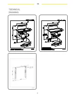
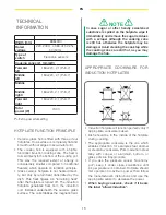
Page 9: ...8 EN TECHNICAL DRAWING ...

Page 10: ...9 EN INSTALLATION SEQUENCE HOLE CUT FOR INSTALLING THE HOB DOWNDRAFT INSTALLATION INSERTION OF THE METAL INSTALLATION STRUCTURE COOKING HOB INSTALLATION ...

Page 11: ...can have a thick ness greater than the worktop because an opening is maintained in the front part of the kitchen unit of at least 5mm refer to design below to ensure an adequate passage of air to avoid overheating the product Before cutting the hole check inside the kitchen unit where the product will be housed to ensure that there are no obstructions such as parts of the unit s structure or anyth...

Page 12: ... length of the duct must not exceed 3 metres in length Avoid drastic changes of direction Utilise a duct with a 150mm or 200mm diam eter along its whole length Utilise a duct that is manufactured from ma terial approved to the norm The supplying company will not respond to problems of flow capacity or noise if there is a lack of respect of the previously mentioned instructions and the guarantee wi...

Page 13: ... the lower part of the cooking hob The gasket should be attached to the appliance in the following way Remove the protective film from the gasket Then attach the gasket to the lower side of the glass approximately 2 3 millimetres from the edge The gasket must be attached along the entire length of the glass edge and should not over lap at the corners When installing the gasket make sure that the g...

Page 14: ...supplied Fig 11 2 Permanently block the downdraft utilising the two screws indicated in Fig 12 3 Connect the electrical cables of the down draft as shown in Fig 13 and then carry out the connection to the mains electricity in ac cordance with the information reported on the relative technical data plate 4 After completing the installation and having connected the downdraft to the mains elec tricit...

Page 15: ...C ADJUSTMENT OF SENSORS TO THE AMBIENCE Upon each connection to the power supply the sensors of the appliance are automatically ad justed to the environment to ensure their proper function All displays turn on and are fully illumi nated for a few seconds During the adjustment procedure the sensors must be free of any objects otherwise the ad justment procedure will be interrupted until such object...

Page 16: ...induction coil installed underneath the ceramic glass surface The coil stabilises the magnetic field APPROPRIATE COOKWARE FOR INDUCTION HOTPLATES Induction hotplate will function perfectly only if appropriate cookware is used Dish should be in the middle of the hotplate during cooking The appropriate cookware is the one which enables induction for example steel enamel or steel alloy cookware Pots ...

Page 17: ... is recognized the hotplate will only use the amount of energy re quired to heat the dish according to its size Hotplate may be damaged if it is turned on and left empty or an empty dish is placed on it You use clay dishes which leave scratches on the ceramic glass surface You fail to wipe the dish bottom dry prior plac ing it on the ceramic glass hotplate heat in duction is obstructed and the hot...

Page 18: ...cially economic and save both time and energy Shorter cooking time leaves more vi tamins in food Always leave enough water in steam pressure pots otherwise it may result in overheating which may damage both the pot and the hot plate Always cover the cookware with lids of appro priate size Use such dish size to accommodate the quantity of food to be prepared If you use ex cessively large pot for sm...

Page 19: ...n hotplate front right 5 Hob control panel 6 Downdraft control unit A ON OFF sensor of cooktop C Pause and recall function sensor D Sensor of timer E Sensor of timer F Slide control G Warming function sensor H Booster H Chef cook S H1 HOB CONTROL ELEMENTS SLIDE CONTROL POWER 000 min 5 P 0 0 Medium power Full power C F G H F G H A I E D 025 min 6 F G H F G H P 6 4 1 2 3 5 5 6 ...

Page 20: ...ng the slider F At the first touch the level is set according to the part of the slider that you touch Upon the slider the control LEDs light up according to the level set By sliding along the slider the power level setting is changed By sliding to the right the level increasing while sliding to the left decreases the level When you move your finger away from the slider the cooking field starts to...

Page 21: ...lates Activating the control unit lock The cooktop must be turned on SWITCHING HOTPLATES OFF SWITCHING THE HOB OFF LOCKING THE CONTROL UNIT switched on again the block is off Simultaneously press B and I and immediately after again the button B All displays show the letter L The block is active The safety lock secures all sensors operated by mistake except the sensor A If the hob is turned off whe...

Page 22: ...ages such as A P or no pan are hidden the pause display has priority If there is a general error during the pause the control switches off and terminates the mode NOTE The pause mode can only be active for maximum 10 min If the pause mode is not deactivated within 10min the control switches off automatically Throughout the pause time the A button can be used to switch the control off In this case ...

Page 23: ...ny of the hotplates for all power settings except for setting 9 where power is set at maximum all the time Automatic cooking mode is activated on any idle hotplate Choose the required continuous cooking level and hold it for 3 seconds The activated heat up time automatic will be displayed through alternating between A and the se lected continuous cooking level on the display EXTRA POWERFUL SETTING...

Page 24: ...ion Whether the two zones are working at a different level whether they are at level 0 Simultaneously press anywhere on the slider F of the zones Now the two areas work together the LEDs to the right of the corresponding displays turn on The level is shown on the display of the control zone in the meanwhile the controlled zone s display turns off When this function is active you can set the timer ...

Page 25: ...the melting function The first LED is activated WARMING FUNCTION If the special function key is pressed a second time warming level two is activated The second LED is activated If in 10 uninterrupted minutes no cookware is detected on one of the two elements the bridge func tion is automatically deactivated the uncovered cooking element is switched off and the covered cooking element remains as th...

Page 26: ...erates on several levels When temperature of the hotplate excessively rises it switches on two stage fan If this is not enough extra powerful heating is deactivated and finally the safety device either reduces the heating power of certain hotplates or turns them off completely When the hotplate cools off the full power of hotplate is again available PROTECTION FROM OVERHEATING CHEF COOK FUNCTION T...

Page 27: ...multaneously press sensor D and E the timer s display shows 0 00 and the LED to the right of the display of the first active cooking zone from the left lights on TIMER Simultaneously press D E as many times as necessary to select the zone where you want to set the timer The LED lights on only for the active cooking zones Within 10 seconds since pressing the D E set the timer value by pressing the ...

Page 28: ... Turning timer off When preset time elapses a beep signals the end and the hotplate is switched off Switch off the alarm by pressing the sensor D or E or it switches off automatically after 2 minutes If you want to switch off the timer prior the end of preset time Simultaneously press sensor E and D Simultaneously press D E as many times as necessary to select the zone of which you want to disable...

Page 29: ...prior expiry of preset time Simultaneously press sensor E and D Simultaneously press D E as many times as necessary to select the alerter the respective LED lights on Press D until the value 0 The alerter is deactivated If no cooking zone is active the alerter s LED lights on The timer value is set by pressing sensors D o E It s possible setting time in seconds and minutes also for the alerter A E...

Page 30: ...he error code E36 or Er36 Control unit cuts off Short cir cuit Contact authorized center for technical assistance specifying the error code E31 or Er31 Configuration data incorrect Configuration of induction nec essary Contact authorized center for technical assistance specifying the error code E47 or Er47 Communication error between TC and induction Contact authorized center for technical assista...

Page 31: ...assistance specifying the error code E8 Incorrect fan speed error on fan left or right Air exhaust blocked for example by paper Contact authorized center for technical assistance specifying the error code E9 Coil temperature sensor defec tive Contact authorized center for technical assistance specifying the error code ...

Page 32: ...e it may lose its glow Never use any aggressive sprays or limestone removers Fig C Major stains are removed with special ceramic glass cleansers Follow strictly the manufacturer s instructions Be careful to remove any remains of cleansing agent from the hob surface otherwise they will be heated during the next use and can damage the hob Fig C Stubborn and burnt stains are removed with special cera...

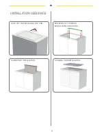
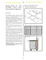
Page 33: ...32 EN DOWNDRAFT ...

Page 34: ...and fitting of the grease and carbon filters need to be carried out with the downdraft in the open position To do this select then remove the front panel by simultaneously pull ing on both sides of the upper part The panel will rotate forwards to make it possible to access the grease filters Fig 15 Remove the grease filters to access the carbon filters Fig 16 The replacement of the charcoal filter...

Page 35: ...AUTION This appliance is fitted with an H05 VVF 3 conductor 0 75 mm2 neutral phase and ground power cord This can be connected up to a 220 240 V mono phase electrical network through a CEI 60083 approved power socket which must remain accessible after installation in compliance with installation regulations We decline any responsibility in case of ac cidents caused by a lack of ground connec tion ...

Page 36: ... cause the carriage to open and then the light will switch on The button also serves to switch off the light if it is on B ON OFF key This starts the extraction carriage upward movement and when it is fully open it sets the second extraction speed With the carriage open it switches off the mo tor and if on the light then it retracts the ex traction carriage C Key This reduces the speed of the extr...

Page 37: ...reset this alarm hold down the TIMER button for at least 3 seconds while the car riage is open Calibration The cooker hood carries out its self calibra tion every 3 complete cycles of its extractable unit By pushing the TIMER key 6 times consec utively MAX break between one push and the other is 3 sec all the leds will flash and the calibration will be reset After the next 3 cycles the downdraft w...

Page 38: ...ned on a regular basis because otherwise they may represent a fire risk Refit the grease filters and front panel making sure that the panis properly fitted at the sides so that it it does not cause the downdraft to stop operating Active charcoal filter In the recirculation mode the active charcoal filter must be replaced pe riodically To remove the charcoal filter first of all it is necessary to r...

Page 39: ...om The kitchen is ventilated well enough to allow air for intake The charcoal filter is not worn out filtering version cooker hood The air outlet channel is free and compliant The non return valves of the suctioning unit are free to rotate The product stops whilst functioning Check that There is not a power outage The omnipolar device has not tripped SERVICE Any maintenance operation on your appli...

Page 40: ...40 IMAGES ...

Page 41: ...41 2 6 3 4 5 1 ...

Page 42: ...42 9 8 7 10 11 12 ...

Page 43: ...43 13 15 16 14 17 ...

Page 44: ...44 ...

Page 45: ...45 ...

Page 46: ...Caple Fourth Way Avonmouth Bristol BS11 8DW www caple co uk 90002422415 Serial number 90002429417 08 15 ...

Reviews: