background image

WC6112

Caple 60cm in-column wine cabinet

Technical information

Summary of Contents for WC6112

Page 1: ...WC6112 Caple 60cm in column wine cabinet Technical information ...

Page 2: ......

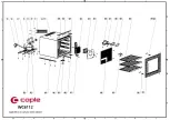
Page 3: ...DG22 480 fixing board for fan 1 16 DG3 207 1 W LED light 1 17 DG13 471 Electrical box 1 18 DG13 470 lid of electrical box 1 19 DG20 260 Display panel 1 DG15 204 1 Wooden shelves 1 DG15 204 Wooden shelves 2 21 DG23 209 door 1 22 M147 003 gasket 1 23 DG22 3109 handle 1 24 DG13 3005 magnet 2 25 DG13 1 2 Humid box 1 26 DG22 472 Air duct board 1 DG20 1 wire clamp 2 DG8 22 Senser 1 DG8 23 Senser 1 28 DG...

Page 4: ......

Page 5: ...ning or maintenance this unit MUST be disconnected from the electrical supply to prevent electrical shock Preparation before maintenance Tools 1 Pliers 2 Phillips head screwdrivers 3 Process pipe 4 Electrical Multi meter 5 Amp meter 5A caliper cable type 6 Electrical soldering iron 7 Wire strippers 8 Seal pliers Equipment 1 Vacuum pump 2 Soldering iron for copper pipes 3 Refrigerant meter 1 Safety...

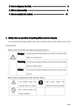
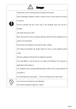
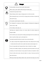
Page 6: ... explain the danger if ignore it Danger This symbol means that the instance may have the chance to suffer death or a serious wound Warning This symbol means that the instance may have the chance to suffer death or a serious wound Notice This symbol means that the instance may have the chance to suffer a wound Below symbols distinguish and rules should be obeyed This symbol means the instance hope ...

Page 7: ...se blast Exhaust the rest refrigerant in the systems before welding After filling the refrigerant the sealing should be done by using smithing welding nozzle Using the welding machine will fire the refrigerant and blast Since the R600a is heavier than the air please let the R600a on the ground go especially for the hypogeum The operation on the servicing refrigerant bottle should be done in place ...

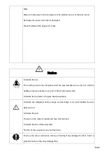
Page 8: ... bottle Don t touch the wine cooler when the cooling pipe damaged don t fie inside the wine cooler keep the windows open to exchange the air Disusing the default compressor should be done outdoor without fire The maximum weight of the refrigerant bottle loaded in the vehicle should be comply to stated the bottle should be place upright the maximum leaning angle is 40 Do use the appointed part othe...

Page 9: ...just stop heater is very hot The hot will cause scald Attention the hot parts of the pipe after the welding Attention the refrigerant during charge and discharge it as it will frostbite the skin when touch it Attention the burr The burr on the metal or plastic part may hurt the hand Attention the fins of the evaporator The fins of the evaporator may hurt the hand Drive up the wine cooler when movi...

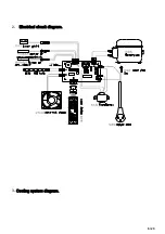
Page 10: ...6 23 2 Electrical circuit diagram 3 Cooling system diagram ...

Page 11: ...off Power Power on off indication light z The default setting temp of this wine cooler is 12 but when restart the wine cooler after power off it will back to the former setting temp before power off z According to customers requirement this wine cooler can be set to that the readout display actual temp or setting temp a In the readout display actual temp mode press the or the systems enter the tem...

Page 12: ...bove description the parts are normal If any part fail check the failed part and the corresponding wiring and connection if the wiring and connection is in good condition replace the part and check again if it still failed the default should be the control PCB replace it with same model 6 2 1 6 2 2 3 The self check can be quit only disconnect the power plug 5 2 Err code Code Representation Checkin...

Page 13: ...r stop the compressor stop the readout keep twinkling The HI alarm can be stopped by disconnect the power plug Low temperature warning After turning on the wine cooler two hours if the inner temperature is lower than 0 ºC and lasting for 15 minutes the readout show LO the buzzer alarm and the compressor stop at the same time when the inner temperature is over 2ºC the LO warning stop Remark some mo...

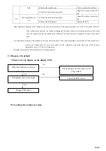
Page 14: ...e door gasket airproof Cooling system default It can be loaded with normal temperature wine bottle Repair or replace the gasket No Yes Abnormality No No Yes Yes Yes No If the inner light can be turn on Check the power source power cord Display err code Refer to 5 2 The starter have power input The protector have power input Check the current of the compressor The starter failed The protector faile...

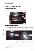
Page 15: ...e air duct board Remove all shelves Remove the air duct board 1 Remove the shelves remove the screws fixing the air duct board remove the air duct board you can see the inner air duct board Fig 2 Fig 2 1 2 Remove the screws fixing inner air duct board disconnect the connecter of the fan and remove the inner air duct board we can see the welding points around the evaporator Fig 3 Diagram show evapo...

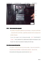
Page 16: ... can see the evaporator is joint to suction pipe and capillary Fig 3 Heat the joint C E Fig 12 in the compressor room and disconnect the pipe from compressor by using the plier Then remove the evaporator and capillary and suction pipe 6 1 4 How to remove the inner fan The process of remove the inner fan remove all shelves remove the air duct board remove the inner air duct board disconnect the fan...

Page 17: ... the shelves Fig 1 loose the fixing screws and the box loose disconnect the connectors then remove the electrical box 6 1 6 How to remove the display board The process of removing the controlled box Remove all shelves loose the fixing screws disconnect the connectors remove the controlled box remove the display PCB Fig 4 Screws Inner air duct board Inner fan Screws fixing inner fan Fig 5 ...

Page 18: ...ake away the display PCB Fig 7 6 1 7 How to remove the LED light The process of removing the LED light Remove all shelves loose the fixing screws disconnect the connectors remove the controlled box remove the LED light Remove the electrical box then remove the screws fixing LED light remove the LED light Fig 6 Fig 7 Screws Fig 6 Fig 7 Slotted screwdrive Controlled box front cover LED light Screws ...

Page 19: ...g power box remove the power box The process of removing transformer Remove the screws fixing power box remove the power box remove the transformer Remove the screws 1 2 fixing power box Fig 8 Remove the power box Fig 9 Remove the screws fixing transformer Fig 9 6 2 2 How to remove the power PCB Screws Barb Power box Main PCB Transformer Screws Fig 8 Fig 9 ...

Page 20: ... PCB upward remove the power PCB Notice It is better to press the barbs by using the cuspate plier Fig 10 Diagram of main PCB connection Fig 11 1 Anti frost sensor red 2 Inner sensor white 3 Door switch 4 Compressor 5 Power N 6 Transformer primary N 7 Transformer secondary 8 Transformer primary L 9 Power L 10 Display 11 Inner fan yellow 12 LED light Fig 11 Fig 10 Main PCB Barb ...

Page 21: ...pressor disconnect the connecting wiring then remove the four basic screws fixing compressor remove the compressor Fig 12 Diagram of soldering joints rear Fig 12 A Jointing pipe and inner condenser pipe joint B Process pipe joint C Discharge pipe joint D Suction pipe joint E Condenser pipe and filter joint F Capillary joint G Condenser and inner condenser pipe joint H Condenser 6 2 4 How to remove...

Page 22: ...ssure the compressor fault replace the compressor please 7 2 Check the cooling system When it is sure that the compressor is working normally and the cooling system s fault is concentrating on the cooling system pipe Check following below 1 Cut off process pipe and check the refrigerant If there is not enough refrigerant the default of the refrigerant system should be caused by the leaking If the ...

Page 23: ...tes Until the vacuum is lower than 100Pa Then solder the process pipe of the filter Keep the vacuum running while soldering this joint 2 Fill Cooling system with refrigerant via the process pipe of the compressor Fig 12 showing B Regarding refrigerant quantity Please refer to the instruction at back label of wine cellar Then solder the compressor process pipe after the system is charged with refri...

Page 24: ...ticles into capillary unit 2 Replace the capillary into the evaporator then solder it back into the correct position not exceeding 15mm in the evaporator and pack the joint with anti vibration compound 3 Recharge with refrigerant 7 3 7 7 Capillary vibration noise Default high frequency impact noise in capillary Zone Caused by either reason below 1 The capillary being insert too deep into the evapo...

Page 25: ... down until it expand to the normal state When it is cool check it with the door closed if there is any distortion dry it again until it fix for the door Fig 13 2 If the fan is broken replace the fan 7 10 Unstable temperatures inside the cabinet The unstable temperature is caused by the evaporator fans cease and it can be check by the below method When the compressor is running the fan should be r...

Page 26: ... Fig 14 4 Cut the sensor the rest wiring should be long enough to reconnect Fig 14 1 5 Peel off the scarfskin about 12mm cut the spare sensor and peel off it s scarfskin about 12 mm connect the ends and wrap the ends with insulating tape Fix the sensor on the original position Fig 15 Fig 15 1 6 If the readout show E3 E4 it means the anti frost sensor open or short circuit the solution same as abov...

Page 27: ...7 1 4 If above process finis it still fault that means the wiring damaged in the foam you have to have another wiring along the bottom and back of the cabinet to connect the switch Rev A LED VERSION Screws scissors 12mm strip 4 Insulating tape Fig 16 Fig 16 1 Fig 17 Fig 17 1 ...

Reviews: