background image

8200-M554-O1 

x

 2XX-EIP 

Page 1 


2XX-EIP 

EtherNet/IP Interface Card 

For 200 Series Indicators 

(205, 210, 215 and 225)  

INSTALLATION MANUAL 


8200-M554-O1 Rev A  203 E. Daugherty, Webb City, MO 64870 USA 

Printed in USA 

03/09 

Ph: 417-673-4631 

y

 Fax: 417-673-2153 


www.cardinalscale.com 


Technical Support: Ph: 866-254-8261 

x

 tech@cardet.com 

Summary of Contents for 2XX-EIP

Page 1: ...Card For 200 Series Indicators 205 210 215 and 225 INSTALLATION MANUAL 8200 M554 O1 Rev A 203 E Daugherty Webb City MO 64870 USA Printed in USA 03 09 Ph 417 673 4631 y Fax 417 673 2153 www cardinalsc...

Page 2: ...8200 M554 O1 x 2XX EIP Page 2...

Page 3: ...o Subpart J of Part 15 of FCC rules which are designed to provide reasonable protection against such interference when operated in a commercial environment Operation of this equipment in a residential...

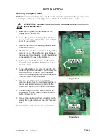
Page 4: ...anel on the workbench next to the indicator 5 Referring to Figure No 1 locate the threaded stand off and the OPTION BOARD connector on the main board 6 To install the option card carefully align the P...

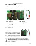
Page 5: ...rd contains 3 LED s to indicate communication status with the indicator main board x CS Chip Select x LK Link x ML Main Line If the CS Chip Select LED is off communications may have been lost between...

Page 6: ...ttern when tightening the acorn nuts 4 Tighten the gland connector nut to seal the cable Do not over tighten the connector but make certain they are snug DO NOT USE TOOLS Finger tighten only Insure an...

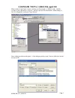
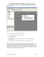
Page 7: ...use an existing set the program in Offline mode Add the module to the configuration in the PLC Start by right click the EtherNet IP module bridge in the I O configuration and select New Module Now a...

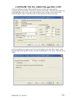
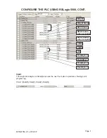
Page 8: ...ame for the module This name will create a tag in RSLogix5000 which can be used to access the memory location in the PLCs memory where the data for the module will be stored With the name entered pres...

Page 9: ...t to download the configuration 5 Select Download The configuration will now be downloaded to the PLC Now it s possible to access the data exchanged by ControlLogix5000 and the module To do this open...

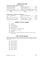
Page 10: ...ight data begins at Data 0 and uses the next four bytes to produce a floating point program tag Float Data 0 Data 1 Data 2 Data 3 Weight Weight Status PWC Status CMD 0 return when complete CMD 1 retur...

Page 11: ...d Byte 1 Word2 Float point value for Cmd Byte 2 Float point value for Cmd Byte 3 Word3 WEIGHT STATUS Data 4 Bit0 MOTION Bit1 BELOW ZERO Bit2 CENTER OF ZERO Bit3 OVER CAPACITY Bit4 WEIGH UNITS 0 unit1...

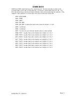
Page 12: ...t point value be sent in Bytes 4 5 6 7 Bit05 not defined Bit06 not defined Bit07 This bit is the error bit from the 2XX when a command fails Bit08 PWC1 requires float point value be sent in Bytes 4 5...

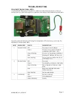
Page 13: ...STATE DESCRIPTION 1 Network Status Off No power or no IP address Green On line one or more connections established CIP Class 1 or 3 Green Flashing On line no connections established Red Duplicate IP...

Page 14: ...2...

Page 15: ...8200 M554 O1 x 2XX EIP Page 12 2XX EIP ADDENDUM For 225 Indicator...

Page 16: ...SCALE 1 Enter Selection 1 EXIT Press the ENTER key then press the NEXT Navigation arrow until SETUP MENU 3 is displayed SETUP MENU 3 1 G N ACCUMS XXX 6 KEY LOCKOUT 2 BACK LITE XX 3 PASSWORD 4 2xx EIP...

Page 17: ...e broken into command bits for PLC ease of programming To invoke a command set the bit to one The PLC should continue to send a command until the command is returned by the indicator If the indicator...

Page 18: ...t6 Select scale number bit 2 Bit7 Select scale number bit 3 most significant WEIGHT STATUS Bit0 Motion Bit1 Below Zero Bit2 Center of Zero Bit3 Over Capacity Bit4 Weigh Units 0 unit 1 PRIMARY UNITS 1...

Page 19: ...2...

Page 20: ...2...

Reviews: