
Manufactured by : MUN AH PLASTIC ELECTRONIC TOYS CO., LTD.
MAN-G00546
Visit Us on www.carisma.com.hk
Printed in China
© 2015 Carisma. All Rights Reserved. Product specifications are subject to change.
Some models shown are prototypes which may vary slightly from what is inside.
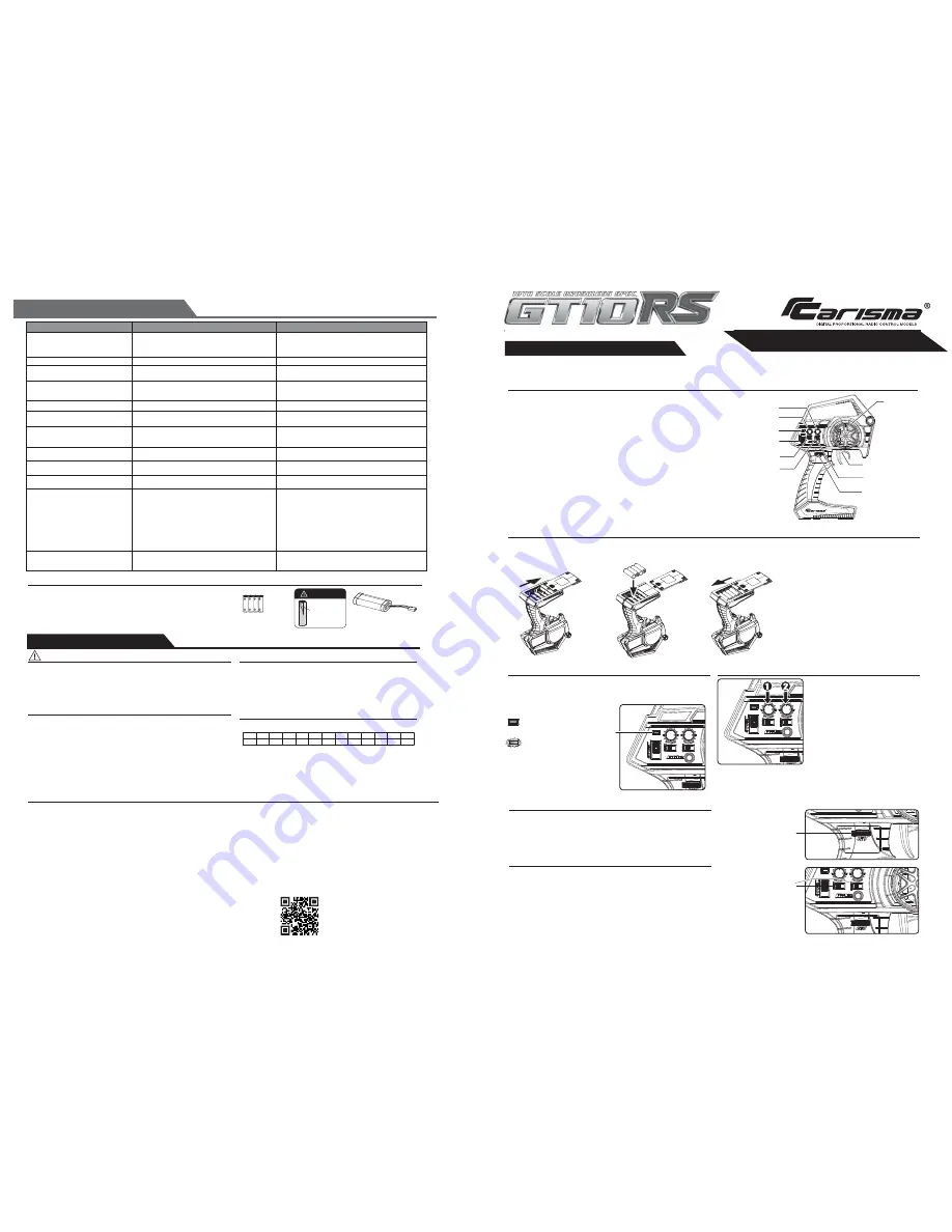
ABOUT THE RADIO SYSTEM
CTX-8000
ST. Trim Dial
TH. Trim Dial
* In general, user will experience under steer when making a wide turn at high speed
or over steer when making sharp turn at high speed (easy to spin out). User should
practice the Throttle and steering approach for different cornering at different speed
or road surface.
Battery Installation
The following is an overview of the various functions and adjustments found on CTX-8000 radio system for Carisma models. It is important to read and
understand about all of these functions and adjustments before driving.
Carisma CTX-8000 2.4GHz FHSS Technology System
Functions
TRANSMITTER CTX-8000
Steering Wheel :
Control direction (Left/Right) of the RC model.
Throttle Trigger :
Control speed and direction (Forward/Brake/Backward)of the
driving model.
ON / OFF Switch :
Power ON / OFF the transmitter.
FTN Key :
Top Green LED light indicates synchronization status and/or adequate
battery power supply.
Power Indicator :
Green LED light indicates Power “ON”. Red LED indicates battery low.
ATV :
Adjust the same maximum steering angle on both sides when model turns
Left / Right.
ST. Trim Dial :
Adjust the neutral position of steering servo when model wheels
are straight ahead.
TH. Trim Dial :
Make sure the model stays still when releasing the Throttle Trigger.
Steering Reverse :
Reverse the response direction when operating Steering Wheel.
Throttle Reverse :
Reverse the response direction when operating Throttle Trigger.
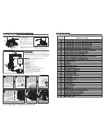
1. Supplied with 4 x 1.5V AA Batteries,
CTX-8000 can be operated a few hours.
Installation: Remove the battery
compartment cover as shown below.
2.Install the batteries observing
the polarity marked on battery
compartment.
3.Then reinstall the battery
compartment cover as the
Picture shown below.
Warning :
Never disassemble batteries or put the batteries
in fire, chemical agents, otherwise they may cause
personal injuries or property damages.
Battery Disposal :
Observe corresponding regulations about wasted
battery treatment regulations.
1. After running out of power, dispose of wasted
batteries in designated areas far away from
water supply, household areas and planted areas.
2. Submit the wasted batteries to specific recycling
stations.
Battery LED Indicator
The Green LED indicator located on the front left side of the transmitter indicates
the power supply of batteries. The green LED will go solid on indicating that
the batteries have sufficient power. When batteries voltage drops below 4
volts, LED will turn to Flashing RED, indicating the batteries power is low and
should be replaced.
Pre-Run Check
Steering
Wheel
Throttle Trigger
Power
Indicator
Steering
Reverse
Throttle
Reverse
ATV
FTN Key
ON/OFF
Switch
* Always turn on the transmitter first by sliding
the switch on the left side from bottom to top.
The small red and green lights above the
switch should both light up. If not, you need
to check for low or incorrectly installed
batteries.
Reversing
Reversing is used to change the response direction of steering wheel and throttle
trigger. CTX-8000 Transmitter features 2 reversing functions: Steering Reverse
and Throttle Reverse.
Steering Reverse:
Reverse the response direction when operating steering wheel.
Turning left steering wheel, the model turns right while turning right the model
turns left.
Throttle Reverse:
Reverse the response direction when operating throttle trigger.
Pushing forward throttle trigger the model moves backward while pulling back,
the model moves forward. If necessary you can just use a small screwdriver to
adjust the or responding switches.
ATV enables to adjust the same maximum steering angle of servo on both sides
(Left and Right) when model makes steering. The ATV affects the sensitivity
of servo. Reducing dual rate value can lower the sensitivity of servo and reduce
the same maximum steering angle on both sides. Remember to adjust the ATV
within the adjustment range.
ATV
1. Steering : Adjust the steering trim to keep
the front wheels in straight line when steering
wheel remains in NEUTRAL position.
2. Throttle : Adjust the throttle trim to ensure
the rear wheels stop rotating when throttle
trigger remains in NEUTRAL position.
Solid GREEN :
Sufficient Power supply
Flashing RED
:
Time to replace batteries
INSTRUCTION MANUAL
INSTRUCTION MANUAL
GREEN
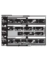
TROUBLE SHOOTING GUIDE
Short running times / Running slow
•
ST. Trim Dial tuning not good
When the Throttle Trigger on Stop
position, Model Car is running
•
Tune the ST. Trim Dial
•
ST. Trim Dial not no center
•
Tune the ST. Trim Dial
Model car out of control
Remote control distance too close
Steering Not working properly
•
Throttle Reverse not set good
L/R Steering phase inversion
Forward/Backward Throttle
phase inversion
•
Check and push the Throttle Reverse SW
•
Steering Reverse not set good
•
Check and push the Steering Reverse SW
•
ESC mode "Forward Only with Brake" is
selected BLUE LED Flashing at STOP position.
3 wire servo No Function
•
5 wire servo is connected
•
Power OFF the unit. Disconnect 5 wire
servo ans power on the unit
ESC NO Function
ESC NO Reverse Function
•
Select ESC mode "Forward / Reverse with Smart
Brake "according to Page X" ESC Program Setup
Flow Chart
Problem
Possible Cause
Solution
• The Battery charge up not full
• The Battery power will ues up
• Wheel Nut too squeeze
• Drive system not soomth
• Recharge the battery full
• Recharge the battery full
• Loosen the Wheel Nut
• Full check the Drive system parts
Running not straight
•
Replace the new AA size alkaline battery
•
Replace the new Receiver
•
Replace the other place
•
Transmitter Battery not power
•
Receiver antenna breakdown
•
Influenced by the environment
•
Transmitter Battery low
•
Model car battery power will ues up
•
Transmitter antenna breakdown
•
Check and Replace the new AA size alkaline battery
•
Check and Recharge the battery full
•
Check or Work on the repairs
•
Servo Gear breakdown
•
Servo Saver breakdown
•
Recharge the new Servo
•
Recharge the new Servo Saver
•
Overheat Proection: RED and BLUE LED
alternative flashing quickly
•
Motor Stalled Protection: RED LED flashes quickly
3 times, Turn OFF for a while and Repeat again.
•
Over Voltage Protection (Battery over 13V):
RED LED SOLID ON and BLUE LED Flashing
ONCE per second.
•
Under Voltage Protection (Battery under
10.2V for 3S LIPO / 6.8V for 2S LIPO / 48V for NiHM):
BLUE LED SOLID ON and RED LED Flashing ONCE
per second.
•
WAIT until the Unit cool down completely
•
WAIT until the Unit cool down completely
•
Replace battery pack
•
Replace battery pack
Receiver No Function
•
Signal Loss
•
Green Led Flashing Twice Continuously
•
Check Transmitter Power on or NOT,
•
or Check Binding is OK or NOT
ATV
Reversing
SAFETY PRECAUTIONS
FOR TRANSMITTER
Damages or
Leaking.
Do not use any
damaged
batteries.
x 4
This product must never be thrown away with other waste. Thus the users are liable for
disposing the wasted model by submitting them to designated collection stations specific
for recycling electronic and electric items. Disposing of the wasted model in this way is
helpful to conserve natural resources and enable to keep human health and protect the
environment. For more information about wasted model disposal and recycling, please
contact your local city office, your disposal service or where you purchased the product.
Instructions for Disposal of WEEE by Users in the European Union
Heavy Duty
1.5V “AA” Size Batteries
(INCLUDED)
ATTENTION
Car Battery
(NOT INCLUDED)
Safety Precautions
Introduction
THIS MODEL IS ONLY SUITABLE FOR PEOPLE 14 YEARS OLD AND UP.
THIS RADIO CONTROL MODEL IS NOT A TOY.
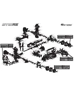
Beginner should seek advice from experienced person in order to assemble the model
or parts correctly and to make best performance.
* Assemble this model or parts only in place out of children’s reach, and take safe
precautions before operating this model. User is fully responsible for the model
assembly and safe operations.
This is a sophisticated hobby product and not a toy. It must be operated with
caution and common sense. User also requires some basic mechanical abilities.
Fail to operate this product in a safe and responsible manner could result in injury
or do damage to the product or other properties. This product is not intended for
use by children without direct adult supervision. The product manual contains
instructions for safe operation and maintenance. It is essential to read and follow
all the instructions and warnings in the manual prior to assembly, setup or use, in
order to operate correctly and avoid damage or injury.
UK
FI
CZ
AT
NL
FR
DE
EE
SK
IT
LU
DK
LV
HU
ES
MT
BG
LT
RO
PT
CY
SE
PL
SI
IE
GR
The associated regulatory agencies of the following countries recognize the
noted certifications for this product as authorized for sale and use.
CE Compliance Information For The European Union
Declaration of Conformity
Products:
Carisma CTX-8000 2.4GHz Transmitter, MRS-540BL Receiver
Equipment Class: 2
The objects of declaration described above are in conformity with the
requirements of the specifications listed below.
Statement - This device complies with Part 15 of the FCC Rules.
Operation is subject to the following two conditions:
(1) this device may not cause harmful interference, and
(2) this device must accept any interference received, including interference
that may cause undesired operation.
FCC ID YDTCTX-8000
RF Exposure Warning:
This equipment complies with FCC radiation exposure limits set forth for an
uncontrolled environment.
And should be operated with minimum distance of 20 cm between the
antenna & your body.
Item Name : Carisma CTX-8000 2.4GHz Transmitter and MRS-540BL Receiver
EN 301 489-1 V1.9.2
EN 301 489-17 V2.2.1
ETSI EN 300 328 V1.8.1
Safety, Precautions, and Warnings
As the user of this product, you are solely responsible for operating it in a manner that
does not endanger yourself and others or result in damage to the product or the property
of others.
This model is controlled by a radio signal that is subject to interference from many sources
outside your control. This interference can cause momentary loss of control so it is
necessary to always keep a safe distance in all directions around your model, as this will
help to avoid collisions or injury.
• Always operate your model in an open area away from cars, traffic, or people.
• Avoid operating your model on the street where injury or damage can occur.
• Never operate the model out into the street or populated areas for any reason.
• Never operate your model with low transmitter batteries.
• Carefully follow the directions and warnings for this product and any optional support
equipments (chargers, rechargeable battery packs, etc.) that you use.
• Keep all chemicals, small parts and anything electrical out of the reach of children.
• Moisture causes damage to electronics. Avoid water exposure to all equipments not
specifically designed and protected for this purpose.
Changes or modifications not expressly approved by the party responsible for
compliance could void the user’s authority to operate the equipment.
Directive 1999/5/EC (R&TTE)
Article 3.1a Health
Article 3.1b EMC
Article 3.2 Radio Spectrum


