background image


FW500

 Service Manual


8/31/2015 


FW500 SE. SERVICE MANUAL 

(Revision 0 / 2013.02.19) 


Summary of Contents for FW500

Page 1: ...FW500 Service Manual 1 8 31 2015 FW500 SE SERVICE MANUAL Revision 0 2013 02 19 ...

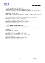
Page 2: ... 1 4 Calibration factor Setting C 10 11 2 1 5 Displaying Real A D Value C 5 12 2 1 6 Percent Calibration C 7 13 2 1 7 Battery Calibration C 8 13 3 The Schematics and Diagram 14 3 1 System Block Diagram 14 3 2 Circuit Diagram 15 3 2 1 FW500C Main PCB 14 3 2 2 FW500C Rear Display PCB 오류 책갈피가 정의되어 있지 않습니다 3 2 3 FW500E Main PCB 16 3 2 4 FW500E Rear Display PCB 16 4 Exploded View 209 5 Load Cell drawin...

Page 3: ...aution Make sure that you plug your scale into the proper power outlet Place the scale on a flat and stable surface Plug into a power outlet 30 minutes before operations Keep the scale away from strong EMI noises may cause incorrect weight readings This scale must be installed in a dry and liquid free environment Do not subject the scale to sudden temperature changes Do not subject the platter to ...

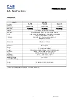
Page 4: ...Hold Ver UNIT Unit Ver POWER Functions Weighing WaterProof level IP 69k Hold Hold Ver Unit Conversion Unit Ver Sleep Mode Function Dimensions 303 x 266 x 109 mm Platter size 212 x 247 mm Weight 2 7 Kg Without Battery Power 1 5V x 4 units D size Battery or 12V 300mAAdapter Operation Time Approx 1200hours Manganese battery 2500hours Alkaline at 20 C 68 F Operating Temperature 10 C 40 C 14 F 104 F Mi...

Page 5: ... Ver Sleep Mode Function Dimensions 303 x 266 x 109 mm Platter size 212 x 247 mm Weight 2 7 Kg Without Battery Power 6 V 3 2Ah Pb battyery 12V 300mA Adapter Operation Time Approx 100hours PB battery Operating Temperature 10 C 40 C 14 F 104 F Minimum Voltage Level of The Battery About 3 3V Option 12V Adapter 300mA Rear Display Notice Specifications are subject to change for improvement without noti...

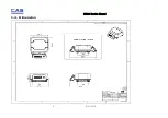
Page 6: ...FW500 Service Manual 6 8 31 2015 1 4 Dimension ...

Page 7: ...FW500 Service Manual 7 8 31 2015 1 5 Dimension TILTING DISPLAY TYPE ...

Page 8: ...FW500 Service Manual 8 8 31 2015 1 6 Sealing method ...

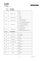
Page 9: ...R Setting TARE key MODE Function CAL 1 Display normalized AD CAL 2 Display Keypad infomation CAL 3 Weight Setting Mode UnLoad TARE MIDD TARE after loading for 1 3 weight FULL TARE after loading for Full weight MIDD TARE after loading for 1 3 weight END CAL 4 Option Setting Refer to Table 1 CAL 5 Display filtered Raw AD CAL 7 Calibration CAL 8 Battery calibration CAL 9 Gravity constant CAL 10 Set c...

Page 10: ...ssive Tare 2 Direction successive Tare 1 Direction successive Tare 0 One Time tare BIT0 1 Zero mark type 0 Gross zero indication 1 Net zero indication 2 Both gross and net zero indication 2 1 1 2 C4 3 Setting BIT7 Dot Type 0 dot 1 comma BIT6 Use Preset tare 0 Don t use 1 Use BIT5 Use Back light 0 Don t use 1 Use BIT4 Use Head message 0 Don t use 1 Use BIT3 Use gram 0 Don t use 1 Use BIT2 Use oz 0 ...

Page 11: ...hree times and shows the version of scale it displays CAL 1 message 12 Press ZERO to display C 9 13 Press TARE key and then G 1 message and 9 7994 will be shown The first digit 9 will blink 14 Input a gravitational acceleration value by using ZERO key 15 Press TARE key and then G 2 message blinks 9 7994 will be shown The first digit 9 will blink 16 Input a gravitational acceleration value by using...

Page 12: ... is 3 will display 0 000 11 Input a weight decimal point by using ZERO key 12 Press TARE key and then 1d message blinks 0 005 will be shown The third digit 0 will blink It means a division is 0 005 calibration unit kg or lb 13 Input a division by using ZERO key 14 Press TARE key and then dual message blinks 1 will be shown The third digit 1 will blink It means a dual interval is disable 0 disable ...

Page 13: ...5 Press TARE key and then it displays pspan message 6 Load choice percentage weight of full weight on the platform 7 Press TARE key and then it displays CAL 7 message 2 1 7 Battery Calibration C 8 1 Pressing and holding Calibration Switch press POWER key After CAL message blinks three times and shows the version of scale it displays CAL 1 message 2 Press ZERO to display CAL 8 3 Press TARE key and ...

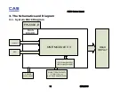
Page 14: ...015 3 The Schematics and Diagram 3 1 System Block Diagram Load Cell REAR DISPLAY LCD Display FW500C LED Display FW500E POWER 12V Adaptor FW 500C E KEY ONE MODULE V3 MAIN BOARD Dry BATTERY FW500C 1 5V D type 4 6 V 3 2Ah Pb bat FW500E ...

Page 15: ...FW500 Service Manual 15 8 31 2015 3 2 Circuit Diagram 3 2 1 FW500C Main PCB ...

Page 16: ...FW500 Service Manual 16 8 31 2015 3 2 2 FW500C Rear Display PCB ...

Page 17: ...FW500 Service Manual 17 8 31 2015 3 2 3 FW500E Main PCB ...

Page 18: ...FW500 Service Manual 18 8 31 2015 ...

Page 19: ...FW500 Service Manual 19 8 31 2015 3 2 4 FW500 E Rear Display PCB ...

Page 20: ...FW500 Service Manual 20 8 31 2015 4 Exploded View 4 1 FW500 ...

Page 21: ...FW500 Service Manual 21 8 31 2015 5 Load Cell drawing 25 112 15 112 SW spring element 2090501 00 ...

Page 22: ...FW500 Service Manual 22 8 31 2015 6 Part Location 6 1 FW500C Main PCB Top Bottom ...

Page 23: ...FW500 Service Manual 23 8 31 2015 6 2 FW500E Main PCB Top Bottom ...

Page 24: ...FW500 Service Manual 24 8 31 2015 6 3 FW500C Rear Display PCB Top Bottom ...

Page 25: ...FW500 Service Manual 25 8 31 2015 6 4 FW500E Rear Dislpay PCB Top Bottom ...

Page 26: ...ht error When scale is in counting mode you must load the weight If you have no weight on your scale you can see this error message Please load the weight on your tray Err 11 The Err 11 means a writing error of the internal nonvolatile memory To recognize this error be sure to check the voltage on the circuit and do calibration procedures If it still has Err 11 replace the digital module Err 12 Th...

Page 27: ...F105JB5NC 1uF C12 C14 C15 3 5 6715CHP01040 CONDENSER CHIP CL05F104JB5NC 0 1uF C1 C2 C3 C4 C5 C6 C7 C8 MC9 C9 C10 C16 12 6 6715CHP02220 CONDENSER CHIP CL05F222JB5NC 2 2nF C11 1 7 6538ID302030 RESISTOR CHIP 1 16W RR0510P 203D 20k R1 R2 R3 R4 R6 R12 R13 R8 R9 R10 R11 not connected 7 8 6538ID301040 RESISTOR CHIP 1 16W RR0510P 104D 100k R5 1 9 6538ID301530 RESISTOR CHIP 1 16W RR0510P 153D 15k R7 1 10 6...

Page 28: ... MC17 2 9 6713CHP04700 CONDENSER CHIP CS1608 680J500NR 47pF C12 C13 C14 3 10 6713CHP06800 CONDENSER CHIP CS1608 680J500NR 68pF C15 C19 C20 C21 4 11 6710CAP0103B RESISTOR CHIP 1 16W 0 01uF 3kv C18 1 12 6291IS058190 DIODE POWER 1N5819 SMD D1 D2 2 13 6294ISW41480 RESISTOR CHIP 1 16W 1N4148 D3 1 14 7821CJM00100 JUMPER 2 54mm Pitch Straight pin header4PIN J1 1 15 7821CJM00100 JUMPER 2 54mm Pitch Straig...

Page 29: ... CHIP 1 10W 1608 RR0816P 101F 100 1 R4 1 27 6528IF301030 RESISTOR CHIP 1 10W 1608 RR0816P 103F 10k 1 R17 1 28 6528IF301040 RESISTOR CHIP 1 10W 1608 RR0816P 104F 100K 1 R5 R6 R7 R8 R10 R11 6 29 6528IF303630 RESISTOR CHIP 1 10W 1608 RR0816P 363F 36k 1 R9 1 30 7600STA1102S TACT S W MT1102S 2 SMD 4 3MM SW1 1 31 7600STA1105B TACT S W KPT 1105B DJTA 1102C SW2 SW3 SW4 SW5 4 32 6100PFW00000 pcb 6100PFW000...

Page 30: ...103B RESISTOR CHIP 1 16W 0 01uF 3kv C4 1 10 6713CHP01020 CONDENSER CHIP CS1608 102J500NR 1nF MC12 MC13 MC14 3 11 6291IS058190 DIODE POWER 1N5819 SMD D1 D4 D2 D3 4 12 6294ISW41480 RESISTOR CHIP 1 16W 1N4148 D5 1 13 7620s0516000 FUSE 1 6A 250V ø5 UL S VDE BSI 유 1 14 7630S0002060 FUSE HOLDER FC 51 Fuse Clip HD1 HD2 2 15 7821CJM00100 4 pin HEADER 2 54mm Pitch Straight pin header J1 1 16 7821CJM00100 3...

Page 31: ... SWITCHING DIODES MMBD2836LT1 MQ5 1 33 6528IF310000 RESISTOR CHIP 1 10W 1608 RR0816P 104F 100K 1 R1 R4 R5 R22 R35 5 34 6528IF000000 RESISTOR CHIP 1 10W 1608 RR0816P 000F 0 1 R2 R3 R19 R20 R21 R37 R38 R39 R40 R41 10 35 6528IF301030 RESISTOR CHIP 1 10W 1608 RR0816P 103F 10K 1 R42 1 36 6528IF001010 RESISTOR CHIP 1 10W 1608 RR0816P 101F 100 1 R3 1 37 6528IF303330 RESISTOR CHIP 1 10W 1608 RR0816P 333F ...

Page 32: ...816P 470F 47 1 R33 R36 2 50 6528IF303630 RESISTOR CHIP 1 10W 1608 RR0816P 363F 36k 1 R34 1 51 7600STA1105B TACT S W KPT 1105B DJTA 1102C SW1 SW2 SW3 SW4 4 52 6242I003406A IC DC DC CONVERTER MC34063AD U1 1 53 6220IS0A3320 IC REGULATOR XC6204A332MR 3 3V U2 1 54 6224I0058170 IC CS5817 SMD U3 1 55 6241IS003930 IC LINEAR LM393D SOP U4 1 56 7230D0030560 LED KHN305613 3DIGIT CATHODE U5 U7 2 57 6220IS0780...

Page 33: ... CONNECTOR CN1 1 4 7809CAL00220 CONNECTOR 53047 2PIN CONNECTOR CN2 1 5 6713CHP01040 CONDENSER CHIP CS1608 104J500NR 100nF C1 1 6 6670T0016080 INDUCTANCE MMZ1608S102AT L1 L2 2 7 6538ID301530 RESISTOR CHIP 1 16W RR0510P 153D 15k R1 R2 R3 3 8 6528ID000000 RESISTOR CHIP 1 10W RR0816P 000D 0 R4 R6 R7 3 9 6528ID300220 RESISTOR CHIP 1 10W 1608 RR0816P 222D 2 2K R5 1 10 6224I0016210 IC LCD DRIVER HOLTEX H...

Page 34: ...104J500NR 100nF C1 C2 2 4 6713CHP01050 CONDENSER CHIP CS1608 105J500NR 1uF C3 1 5 7232DR050330 LED LAMP ø5 RED 40 mcd LSR 50330 ZERO RED1 TARE RED1 STABLE RED1 LOW_BAT RED1 4 6 723299950150 LED LAMP 고무 지지대 ø5 LED 고무 지지대 4 7 6670T0005000 INDUCTANCE BLM18BB050SN1 L1 1 8 6670T0016080 INDUCTANCE MMZ1608S102AT L2 1 9 6527ID00470 RESISTOR CHIP 1 10W RR1220P 470D 47 R1 R2 2 10 6527ID003900 RESISTOR CHIP ...

Page 35: ...ce Manual 35 8 31 2015 11 6538ID301530 RESISTOR CHIP 1 16W RR0510P 153D 15k R11 R12 2 12 6224I0058170 IC CS5817 SMD U3 1 13 7230D0030560 LED KHN305613 3DIGIT CATHODE U5 U7 2 14 6110PFW00010 LED REAR DISPLAY PCB 1 ...

Page 36: ...n Q ty 1 7840W0004640 CONNECTOR WIRE Φ5 28AWG 9C 5C 360MM_LED 1 2 7840W0004641 CONNECTOR WIRE Φ5 28AWG 9C 3C 360MM 케이스홀드_LCD 1 3 7840W0004642 CONNECTOR WIRE Φ5 28AWG 9C 5C 620MM_REAR 1 4 7840W0004643 CONNECTOR WIRE 16BNC 02R 2P 120MM_POWERCABLE 1 7562P121000F SMPS ADAPTOR 100 240V 12V1 5A KOR 콘넥터 5M 1 ...

Page 37: ...IPTION Unit Q ty 1 2000A0003900 BODY FW500 240 3 238 EA 1 2 2000A0003910 BATTERY COVER FW500 161 134 13 EA 1 3 2000A0002940 BATTERY COVER BOLT ø16 7 EA 4 4 2630A0000760 BATTEY RUBBER FW 500 415mm EA 1 5 2000A0003920 FOOT 40 53 EA 4 6 1575A0012160 MEMBRANE VENT 30 16 0 3t EA 1 7 2022A0000041 WATER LEVEL GAGE ø14 9 8 S 2000 상보 EA 1 ...

Page 38: ...0 WATER LEVEL GAGE COVER GAGE COVER POSCALE EA 1 9 1502MSU04120 M SCREW M4X12 M SCREW M4X12 EA 1 10 1510MSU04120 T SCREW M4X12 T SCREW M4X12 EA 11 11 1000A0001500 BATTERY BRACKET 45 50 1 2t EA 1 12 1540MSU06000 NUT HEX M6 8 SUS EA 4 13 글루건 EA 0 005 ...

Page 39: ...A0003850 REAR DISPLAY CASE FW 500 202 87 36 EA 1 3 2000A0003860 DISPLAY BRACKET FW 500 84 83 32 EA 1 4 2000A0003870 DISPLAY BRACKET COVER FW 500 80 79 10 EA 1 5 2630A0000780 DISPLAY O RING FW 500 520mm EA 1 6 7640S0012620 BUSHING TAIL ø7 27 EA 2 8 7840W0003140 CONNECTOR WIRE ø13 16 EA 1 9 7810C0000220 SOCKET CAP ø17 8 6 1 EA 1 ...

Page 40: ... 8 SUS SCREW MACHINE WPH M3 8 SUS EA 7 12 2630A0000090 O RING O RING P15 EA 1 13 1502MSU03080 M SCREW M3X8 M SCREW M3X8 EA 2 14 1000A0001490 SEALING PLATE FW 500 29 17 1t EA 1 15 2620A0000380 SEALING RUBBER FW 500 32 7 20 9 EA 1 16 9900A0000010 BOLT SEALING M3 26 NT 200 201A 황동 EA 2 17 9900A0000020 SEALING Φ10 5 6 EA 1 ...

Page 41: ...5 1 3 TRAY ASS Y PPPFW4MTRYPPPPP1 No Image Part Code Parts Name DESCRIPTION Unit Q ty 1 1000A0001480 TRAY SUS FW 500 266 231 70 5 0 8t EA 1 2 2000A0003880 TRAY ABS FW 500 247 212 15T EA 1 4 1502MSU0412 M SCREW M4X12 M SCREW M4X12 EA 4 ...

Page 42: ...me DESCRIPTION Unit Q ty 1 2000A0003890 UPPER CASE FW 500 240 215 56 EA 1 2 1502MSU03080 M SCREW PH M3 8 EA 10 3 2630A0000760 BATTEY RUBBER FW 500 415mm EA 1 4 2620A0000370 PLATFORM RUBBER 99 4 5 EA 1 5 1000A0001470 BELLOWS PLATE 99 5 1 6t EA 1 6 1000A0001460 PLATFORM RUBBER GUIDE FW 500 55 1 6T EA 1 ...

Page 43: ...01270 UPPER PLATFORM FW 500 123 59 27T EA 1 2 1030A0004910 LOWER PLATFORM FW 500 142 73 13 6T EA 1 3 1533MSU05120 BOLT WRENCH FH M5X12 BOLT WRENCH FH M5X12 EA 4 4 1532MSU04150 BOLT WRENCH ST M4 15 SUS BOLT WRENCH ST M4 15 SUS EA 4 5 1540MSU04000 NUT HEX M4 07 SUS NUT HEX M4 07 SUS EA 4 6 1510MSU0412 T SCREW M4X12 T SCREW M4X12 EA 4 ...

Page 44: ...it Q ty 1 9104A0000150 C T BOX FW500 426 326 166 EA 1 2 9204A0000080 STYROFORM BOX LOWER FW500 420 310 80 EA 1 3 9204A0000090 STYROFORM BOX UPPER FW500 420 310 80 EA 1 4 9106A0000050 CT GUIDE FW500 750 X 30 X 5 EA 1 5 MANUAL EA 1 6 9305A000001B POLY BAG 500 650 0 04T S2000 SET HD EA 1 7 9400A0000460 SILICAGEL EA 2 ...

Page 45: ...art Code Parts Name DESCRIPTION Unit Q ty 1 9020FW410330 Sticker Warning EA 1 2 9020FW420330 Sticker Spec EA 1 3 9020FW43033 0 Sticker Sus Tray Sticker FW 500 52 5 1t EA 1 4 3070FW400330 FRONT DISPLAY CASE EA 1 5 9020FW44033 0 Sticker COVER EA 1 6 9020 FW4 1533 0 CAPASticker Capa ...

Page 46: ...I 200S SUS M6 7 EA 2 4 1000A000168A TILTING DISPLAY BRACKET FW500 76 60 60 1 2t SUS304 EA 1 8 1 3 FW500 Design part No Part Name Type Material Design Code KO Design Code EN 1 Front Display Case LCD 필름인서트 사출 3070 FW4 0000 0 3070 FW4 0033 0 2 Rear Display Case LCD 필름인서트 사출 3070 FW5 0000 0 3070 FW5 0033 0 3 Front Display Case LED 필름인서트 사출 3070 FW6 0000 0 3070 FW6 0033 0 4 Rear Display Case LED 필름인서트 ...

Page 47: ... Spec 스티커류 Silver oiled paper 9020 FW4 2000 0 9020 FW4 2033 0 8 Sticker Sus Tray Sticker 스티커류 Transparent Sticker 9020 FW4 3000 0 9020 FW4 3033 0 Sticker COVER 9020 FW4 4000 0 9020 FW4 4033 0 9 Sticker Capa 스티커류 Silver oiled paper 9020 FW4 0633 0 10 Sticker Capa 스티커류 Silver oiled paper 9020 FW4 1533 0 11 Sticker Capa 스티커류 Silver oiled paper 9020 FW4 3033 0 ...

Reviews: