background image

1

Part  I

MIDI Message Overview

1   Product Configuration as a MIDI Device............................................................................................ 7

        1.1   Controller Block......................................................................................................................................... 7
        1.2   Sound Source Block.................................................................................................................................. 7
        1.3   Sound Source Common Sub-blocks ......................................................................................................... 8
        1.4   Sound Source Instrument Part Sub-block................................................................................................. 8
        1.5   MIDI Send by Auto-accompaniment, Song Memory, and the SMF Player ............................................... 8

2   Conditions that Disable Message Send and Receive ........................................................................ 8

3   Conditions that Disable Bulk Dump Session Send and Receive ....................................................... 8

4   Different Operations Depending on Part Mode .................................................................................. 9

Part  II

Channel Message

5   Receive Channel................................................................................................................................ 9

6   Send Channel .................................................................................................................................... 9

7   Note Off.............................................................................................................................................. 9

8   Note On............................................................................................................................................ 10

9   Polyphonic Key Pressure ................................................................................................................. 10

10   Control Change .............................................................................................................................. 10

        10.1   Bank Select (00H) ................................................................................................................................. 11
        10.2   Modulation (01H)................................................................................................................................... 11
        10.3   Data Entry (06H,26H)............................................................................................................................ 11
        10.4   Volume (07H) ........................................................................................................................................ 12
        10.5   Pan (0AH) ............................................................................................................................................. 12
        10.6   Expression (0BH) .................................................................................................................................. 12
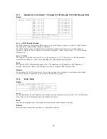
        10.7   General Use Controllers 1 through 8 (10H through 13H, 50H through 53H) ........................................ 13
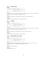
        10.8   Hold1 (40H)........................................................................................................................................... 13
        10.9   Sostenuto (42H) .................................................................................................................................... 14
        10.10   Soft (43H)............................................................................................................................................ 14
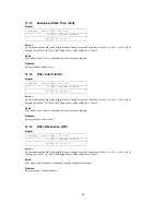
        10.11   Envelope Release Time (48H) ............................................................................................................ 14
        10.12   Envelope Attack Time (49H) ............................................................................................................... 15
        10.13   Filter Cutoff (4AH) ............................................................................................................................... 15
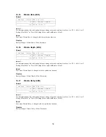
        10.14   Filter Resonance (47H) ....................................................................................................................... 15

MIDI Implementation for the CTK-900, WK-3200, and WK-3700

Important

!

• All mentions of "this Model" in this document refer to the CASIO CTK-900, WK-3200, and WK-3700.

Contents

Summary of Contents for CTK-900

Page 1: ...ceive Channel 9 6 Send Channel 9 7 Note Off 9 8 Note On 10 9 Polyphonic Key Pressure 10 10 Control Change 10 10 1 Bank Select 00H 11 10 2 Modulation 01H 11 10 3 Data Entry 06H 26H 11 10 4 Volume 07H 12 10 5 Pan 0AH 12 10 6 Expression 0BH 12 10 7 General Use Controllers 1 through 8 10H through 13H 50H through 53H 13 10 8 Hold1 40H 13 10 9 Sostenuto 42H 14 10 10 Soft 43H 14 10 11 Envelope Release Ti...

Page 2: ...n Depth 21 10 21 5 Null 22 10 22 All Sound Off 78H 22 10 23 Reset All Controllers 79H 22 11 Mode Message 23 11 1 All Notes Off 7BH 23 11 2 Omni Off 7CH 23 11 3 Omni On 7DH 23 11 4 Mono 7EH 23 11 5 Poly 7FH 23 12 Program Change 24 12 1 About the Part Mode 24 13 Channel Aftertouch 24 14 Pitch Bend 24 Part III System Message 15 Active Sensing 25 16 System Exclusive Message 25 16 1 Universal Realtime ...

Page 3: ...sum Check Sum 37 17 2 13 14 EOX End of System Exclusive Message 37 18 Parameter Operations 38 19 Parameter Set Transfer Protocols 38 19 1 Communication Protocols 38 19 2 One way Protocol Communication Flow 39 19 3 Handshake Protocol Communication Flow 40 Part V Parameter Lists 20 Command Parameters 43 20 1 System Parameter List 43 20 2 Data Management Command Parameter List 44 20 3 Command Paramet...

Page 4: ... 2BandEQ 66 40 4 Algorithm 03 03H 3BandEQ 66 40 5 Algorithm 04 04H LFO Wah 66 40 6 Algorithm 05 05H Auto Wah 66 40 7 Algorithm 06 06H Compressor 67 40 8 Algorithm 07 07H Limiter 67 40 9 Algorithm 08 08H Distortion 67 40 10 Algorithm 09 09H Stereo Phaser 67 40 11 Algorithm 10 0AH Phaser 67 40 12 Algorithm 11 0BH Rotary 67 40 13 Algorithm 12 0CH Overdrive Rotary 67 40 14 Algorithm 13 0DH Enhancer 67...

Page 5: ...9 Algorithm M18 32H Multi18 73 41 20 Algorithm M19 33H Multi19 73 41 21 Algorithm M20 34H Multi20 73 41 22 Algorithm M21 35H Multi21 73 41 23 Algorithm M22 36H Multi22 74 41 24 Algorithm M23 37H Multi23 74 41 25 Algorithm M24 38H Multi24 74 41 26 Algorithm M25 39H Multi25 74 41 27 Algorithm M26 3AH Multi26 74 41 28 Algorithm M27 3BH Multi27 75 41 29 Algorithm M28 3CH Multi28 75 41 30 Algorithm M29...

Page 6: ...ency Setting Value Table 77 42 15 Equalizer Gain Setting Value Table 78 42 16 DSP Algorithm ID Table 78 42 17 Drawbar Position Setting Value Table 78 42 18 Drawbar Percussion Setting Table 78 Part IX MIDI Implementation Notation 42 19 Hexadecimal Notation 79 42 20 Binary Notation 79 ...

Page 7: ...on switch WK 3700 modulation wheel etc song memory auto accompaniment panel operations etc An operation causes the corresponding message to be sent to the sound source and from MIDI OUT Though the Controller Block is mainly a send function turning on MIDI IN Chord Judge configures it to perform chord judgment on received data and send the matching auto accompaniment play data The channel number of...

Page 8: ... messages 1 5 MIDI Send by Auto accompaniment Song Memory and the SMF Player This document provides information about which operations are sent by each message Note however that when an auto accompaniment Song Memory or SMF Player operation is performed MIDI messages may be sent as part of playback data Such data is not covered here Also note that auto accompaniment and Song Memory play data is se...

Page 9: ...I Channel Number 6 Send Channel Basically the MIDI Channel of the Channel message that is sent when play data or parameter setting is changed is the value that corresponds to the part that is playing or the parameter that was changed When the performance part or part for which the parameter setting is changed is Part 1 however the value depends on the Transpose Function Keyboard Channel value The ...

Page 10: ...nges this Model s performance control status or the corresponding parameter Drawbar Organ Operation Independent drawbar organ settings cannot be configured for each part but multiple parts can use the same drawbar organ settings At this time the drawbar organ related Control Change Message NRPN is recognized by the MIDI Channels of all parts that are using the drawbar organ tone When Drawbar Organ...

Page 11: ...e vibrato function is operated A fixed value of 85 is always sent when the WK 3200 modulation button is operated Receive Receipt adds vibrato of a depth specified by the value to the tone being sounded In the case of a tone that already has vibrato applied receipt of this message increases the vibrato depth 10 3 Data Entry 06H 26H Format Send Sent when there is a change in the parameters assigned ...

Page 12: ...Values and Send Receive Values Send Sent when the pan setting of mixer parts 1 through 16 is changed Receive Receipt changes the Mixer part pan setting 10 6 Expression 0BH Format Note 1 The setting value matches the value that is sent and received Send Sent when there is a change in the Expression value by an accompaniment function Receive Receipt changes the Expression value Message Format BnH 07...

Page 13: ...operated and when this Model s DSP edit function is used to change the DSP Parameter value Receive Receipt changes the DSP Parameter value Any message received that corresponds to a parameter whose number exceeds the number of parameters for the currently selected DSP is ignored 10 8 Hold1 40H Format Note 1 For information about the relationship between setting values and send receive values see t...

Page 14: ...ing Value Table in Part VIII Setting Values and Send Receive Values Send Sent when the assignable jack is configured for soft and the connected pedal is operated Receive Receipt performs an operation equivalent to a soft pedal operation 10 11 Envelope Release Time 48H Format Note 1 For information about the relationship between setting values and send receive values see 42 5 64 to 0 to 63 Setting ...

Page 15: ...Table in Part VIII Setting Values and Send Receive Values Send Sent when Filter Cutoff is changed with the synthesizer function Receive Receipt changes Filter Cutoff 10 14 Filter Resonance 47H Format Note 1 For information about the relationship between setting values and send receive values see 42 5 64 to 0 to 63 Setting Value Table in Part VIII Setting Values and Send Receive Values Send Sent wh...

Page 16: ... Part VIII Setting Values and Send Receive Values Send Sent when Vibrato Depth is changed with the synthesizer function Receive Receipt changes Vibrato Depth of Tone Parameter 10 17 Vibrato Delay 4EH Format Note 1 For information about the relationship between setting values and send receive values see 42 5 64 to 0 to 63 Setting Value Table in Part VIII Setting Values and Send Receive Values Send ...

Page 17: ... Receipt changes Chorus Send of Mixer Part 1 through 16 10 20 NRPN 62H 63H Format 10 20 1 Filter Cutoff Format Note 1 For information about the relationship between setting values and send receive values see 42 5 64 to 0 to 63 Setting Value Table in Part VIII Setting Values and Send Receive Values Message Format BnH 5BH vvH n MIDI Channel Number vv Value Note 1 Message Format BnH 5DH vvH n MIDI Ch...

Page 18: ... Position Format Note 1 The table below shows the relationship between the Drawbar Foot value and the position of the foot bar Note 2 For information about the relationship between setting values and send receive values see 42 17 Drawbar Position Setting Value Table in Part VIII Setting Values and Send Receive Values Message Format BnH 62H 21H 63H 01H 06H mmH 26H H n MIDI Channel Number mm Value N...

Page 19: ...ting values and send receive values see the 42 1 Off On Setting Value Table in Part VIII Setting Values and Send Receive Values Send Sent when 2nd Percussion of Drawbar Organ Parameter is changed on this Model Receive Receipt changes 2nd Percussion of Drawbar Organ Parameter 10 20 6 Drawbar Organ 3rd Percussion Format Note 1 For information about the relationship between setting values and send re...

Page 20: ...awbar Parameter 10 21 RPN 64H 65H Format 10 21 1 Pitch Bend Sensitivity Format Note 1 The setting value matches the value that is sent and received Send Same value sent over channels 1 through 5 when the Bend Range parameter of Transpose Function is changed Receive Receipt changes Pitch Bend Sensitivity Message Format BnH 62H 0CH 63H 40H 06H mmH 26H H n MIDI Channel Number mm Value Note 1 Ignored ...

Page 21: ...0 to 24 Setting Value Table in Part VIII Setting Values and Send Receive Values Send Sent when Coarse Tune of Mixer Part 1 through 16 is changed by operation of this Model Receive Receipt changes Coarse Tune of Mixer Part 1 through 16 10 21 4 Modulation Depth Format Note 1 The setting value matches the value that is sent and received Send This message is never sent Receive Receipt changes Vibrato ...

Page 22: ...e Receipt initializes controller values as shown below Message Format BnH 64H 7FH 65H 7F n MIDIChannelNumber Message Format BnH 78H 00H n MIDIChannelNumber Message Format BnH 79H 00H n MIDIChannelNumber Message Number Controller Value Control Change 01H 02H 04H 0BH 40H 42H 43H 65H 64H 63H 62H Modulation Breath Controller Foot Controller Expression Hold1 Sostenuto Soft RPN MSB LSB NRPN MSB LSB 00H ...

Page 23: ...re never sent Receive Receipt of any of these messages releases same as releasing the keyboard key the currently sounding voice Message Format BnH 7BH 00H n MIDIChannelNumber Message Format BnH 7CH 00H n MIDIChannelNumber Message Format BnH 7DH 00H n MIDIChannelNumber Message Format BnH 7EH 00H n MIDIChannelNumber Message Format BnH 7FH 00H n MIDIChannelNumber ...

Page 24: ...ode Melody tones are set to Melody Mode rhythm tones that use the drum map are set to the Drum Mode and drawbar organ tones are set the to Drawbar Organ Mode 13 Channel Aftertouch Format Send These messages are never sent Receive Receipt of this message adds vibrato to the voice that is sounding Details of the effect differ according to the tone setting 14 Pitch Bend Format Send Sent when the bend...

Page 25: ...eive Universal System Exclusive Messages as well as System Exclusive Messages that have a format that is unique to this Model 16 1 Universal Realtime System Exclusive Message Format 16 1 1 Master Volume Format Note 1 The setting value matches the value that is sent and received Send This message is never sent Receive Receipt changes the Master Volume parameter Note that the Master Volume parameter...

Page 26: ...art VIII Setting Values and Send Receive Values Send Sent when the Fine Tune parameter of Transpose Function is changed Receive Receipt changes the Fine Tune parameter 16 1 4 Master Coarse Tuning Format Note 1 For information about the relationship between setting values and send receive values see 42 4 24 to 0 to 24 Setting Value Table in Part VIII Setting Values and Send Receive Values Send Sent...

Page 27: ...t is sent and received Send Sent when the Reverb Time parameter of System Reverb is changed Receive Receipt changes the Reverb Time parameter 16 1 6 Chorus Parameter Format Type Format Message Format F0H 7FH 7FH 04H 05H 01H 01H 01H 01H 01H ppH vvH F7H pp Parameter vv Value Message Format F0H 7FH 7FH 04H 05H 01H 01H 01H 01H 01H 00H vvH F7H vv Value Note 1 Message Format F0H 7FH 7FH 04H 05H 01H 01H ...

Page 28: ...tem Chorus Depth Format Note 1 The setting value matches the value that is sent and received Send Sent when the Chorus Depth parameter of System Chorus is changed Receive Receipt changes the Chorus Depth parameter of System Chorus Feedback Format Note 1 The setting value is the same as the value that is sent Send This message is never sent Receive Receipt changes the Chorus Feedback parameter The ...

Page 29: ... puts the sound source into a GM sound source mode GM System Off Format Send This message is never sent Receive Receipt returns the sound source to its normal mode GM2 System On Format Send This message is never sent Receive Though this Model does not support GM2 receipt of the GM2 System On message has the same result as receipt of the GM System On message Message Format F0H 7FH 7FH 04H 05H 01H 0...

Page 30: ... 900 WK 3200 WK 3700 System Exclusive Message Format These messages can control most of the this Model s parameters as well as user data send receive with Flash memory and come commands For more information see Part IV This Model s System Exclusive Messages Message Format F0H 41H 10H 42H 12H 40H 00H 7FH 00H 41H F7H Message Format F0H 44H 11H 02H F7H ...

Page 31: ...ccordance with the value of the Action field of this Model s SysEx message The basic format for all operation type messages is described in 17 2 Message Structure below CTK 900 WK 3200 WK 3700 System Exclusive Messages Individual Parameter Transfer Command Status and Commands Patch Common MIDI Tune Mix Sys Chorus Sys Reverb Master EQ DSP Part Basic Tune Mix Tone Drawbar Vibrato Wave Data Informati...

Page 32: ...s Model is shown by two consecutive bytes MSB LSB CTK 900 WK 3200 WK 3700 Model ID MSB 11H LSB 02H 17 2 4 4 dev MIDI Device ID 00H through 1FH 7FH The contents of this field in a received message are compared with the Model s MIDI Device ID and receipt of the incoming message is allowed only when the two IDs match The default value for this field is 10H When a message containing 7FH is received re...

Page 33: ... Message Type 00H IPC Individual Parameter Change 01H IPR Individual Parameter Request 02H BDR Oneway Parameter Set Bulk Send 03H BDR Oneway Parameter Set Bulk Request 04H HDS Handshake Parameter Set Bulk Send 05H HDR Handshake Parameter Set Bulk Request 06H Reserved 07H Communication Control for Handshake EOD HDA HDJ HDE BSY EOS NOP Format 0000ccccB Category Action act ID c Parameter Set IPC IPR ...

Page 34: ...h dddddB indicates the size of each data unit parameter in the data field The data length differs according to Message Type as shown below 17 2 9 9 ps Parameter Set Number This field is a 2 byte LSB MSB value indicating the number of the parameter set 00mmmmmmmnnnnnnnB Binary being transferred Format 0pppppppB Format 0iidddddB act Value Message Type iiB 00 01 IPC IPR index byte size 1 Example When...

Page 35: ... 0NNNNNNNB Packet Number MSB As detailed in the data field explanation up to 128 bytes of data can be send in one packet When sending data in excess of 128 bytes it is divided into 128 byte packets final packet can be less than 128 bytes and received data is stored at the address equivalent to ParameterSet Start Address PacketNumber 128 i 2 0LLLLLLLB data length 3 The data length is the data lengt...

Page 36: ...way Handshake Bulk Dump End of Data Parameter set transfer complete HDA Handshake Bulk Dump Acknowledge Handshake receive successful HDJ Handshake Bulk Dump Reject Handshake rejected stopped HDE Handshake Bulk Dump Error Handshake Error BSY Handshake Bulk Dump Busy Handshake Busy EOS Oneway Handshake Bulk Dump End of Package Parameter set package complete NOP No Operation No operation When act 1 I...

Page 37: ...r session and data from different parameter sets cannot be mixed within a single packet even when sending multiple parameter sets Different parameter sets are always divided into separate packets 17 2 12 12 sum Check Sum This field is always empty In this case the sum field contains a value which when added to the total value of the data field makes the lower seven bits 0 The receiving side checks...

Page 38: ... Set send receive Handshake mode Parameter Set send request receive rejected error notification send receive With the one way mode the sending device sends data and ends the session without regard to the response of the receiving device This mode is best for one way transfers from a sequencer or similar device With the handshake mode the sending device sends the data and then waits for a response ...

Page 39: ... of one subsession or multiple subsessions with EOS End of session sent at the end to terminate the send Regardless of whether there is a single Parameter Set or multiple Parameter sets an actual bulk dump always takes the form of a session never a subsession only 19 2 One way Protocol Communication Flow A session starts with the receiving device sending a request using a BDR or with the sending d...

Page 40: ... If an error repeats a number of times undefined either the sending device or the receiving device sends an HDJ to terminate the session A session ends after the sending device sends all the parameter sets and sends a final EOD in response to an HAD ACK from the sending device The same packet is resent when a checksum mismatch or incompatible data structure error is detected Data send is canceled ...

Page 41: ...odel enters a session enabled mode or use a Prepare for Data Management parameter see 20 2 Data Management Command List to change to a communication enabled mode Data Receiver Data Sender Operation HDR Send Request Optional HDS Data Send HDA Acknowledge HDS Data Send HDJ Rejection Send Canceled Data Receiver Data Sender Operation HDR Send Request Optional HDS Data Send HDA Acknowledge HDS Data Sen...

Page 42: ...mpatible data structure error is detected Data Receiver Data Sender Operation BDS Data Send BSY Busy Send Canceled Data Receiver Data Sender Operation HDR Send Request BSY Busy Send Canceled Data Receiver Data Sender Operation HDS Data Send BSY Busy Send Canceled ...

Page 43: ...t for the Setting Value column all values in the Parameter Lists are hexadecimal unless specifically noted otherwise Note 3 Receipt of a value outside a specified range causes the value marked Default to be used instead 20 Command Parameters The parameters defined here mainly execute commands and indicate statuses Values indicate the pointer to a command or a status 20 1 System Parameter List Syst...

Page 44: ...ement Command Parameter List System Exclusive Format ParamID Parameter ps index bit Value Default Setting Value Decimal 00r Model Version ID Note 1 0000 00 0E 05 0 nn00 reserved nn01 CTK 691 nn02 WK 3000 nn03 WK 3500 nn04 reserved nn05 CTK 900 nn06 WK 3200 nn07 WK 3700 n version 00to3F 03 DSP Bypass Note 2 0000 00 10 0 FFFF 0 Bit0 Part1 Bit1 Part2 Bit15 Part16 0 Nop 1 DSP cancel Field Value 01 SYS...

Page 45: ...not include previously stored user parameter sets or song data This means that all Mixer parameters are included The LCD contrast setting is not affected Note 7 The initialization target is the entire Flash memory which is returned to its initial factory default state ParamID Parameter ps index bit Value Default Setting Value Decimal 20w Prepare for Data Management Note 1 0 00 07 0 127 0 0 Prepare...

Page 46: ...ue Decimal 30 Touch Response 0000 00 02 0 3 1 0 Off 1 Type1 2 Type2 3 Type3 31 Transpose 0000 00 07 28 to 40 to 58 40 24 to 0 to 24 32 Jack Mode 0000 00 02 0 3 0 0 Sustain 1 Sostenuto 2 Soft 3 Rhythm 33 LCD Contrast 0000 00 04 0 12 6 0 to 6 to 12 34 Mixer Hold 0000 00 01 0 1 0 0 Off 1 On 35 AuotHarmonize 0000 00 04 0 9 0 0 9 Type ParamID Parameter ps index bit Value Default Setting Value Decimal 3...

Page 47: ...ix Parameter Field Value 01 SYSEX F0 02 MAN 44 03 MOD 11 02 04 dev Either 00 to 1F or 7F 05 act 00 IPC 01 IPR 06 cat Patch 01 07 prm 00 7F 08 ilen dlen 0 bit size 1 09 ps LSB MSB 00 00 10 index Indicates Bar Number in the case of Drawbar Bar Position 0 in any other case 11 data See the Parameter List 12 sum None 13 EOX F7 ParamID Parameter bit Value Default SettingValue Decimal 00 MIDI Device ID N...

Page 48: ...stem Chorus Note 1 Selects the System Chorus preset type Receipt of GM GS Reset selects Chorus3 The other System Chorus parameters are changed to preset values in accordance with this type value See 42 11 Chorus Type Setting Value Table Note 2 Sets the System Chorus feedback volume Note 3 Adjusts the System Chorus timbre ParamID Parameter index bit Value Default Setting Value Decimal 0C Bar Positi...

Page 49: ... 42 13 Equalizer Mid Frequency Setting Value Table Note 7 Selects the Master EQ mid high range gain See 42 15 Equalizer Gain Setting Value Table Note 8 Selects the Master EQ high range cutoff frequency See 42 14 Equalizer High Frequency Setting Value Table Note 9 Selects the Master EQ high range gain See 42 15 Equalizer Gain Setting Value Table ParamID Parameter bit Value Default SettingValue Deci...

Page 50: ...from this Model s control panel The next 16 parameters are Internal Parameters that cannot be changed on this Model s control panel The range of these parameter values is 0 to 127 regardless of the DSP algorithm However the number of parameter types depends on the DSP algorithm which means that not all User Parameters and Internal Parameters are necessarily available as a particular DSP s paramete...

Page 51: ...aram02 07 00 7F 0 127 43 DSP Internal Param03 07 00 7F 0 127 44 DSP Internal Param04 07 00 7F 0 127 45 DSP Internal Param05 07 00 7F 0 127 46 DSP Internal Param06 07 00 7F 0 127 47 DSP Internal Param07 07 00 7F 0 127 48 DSP Internal Param08 07 00 7F 0 127 49 DSP Internal Param09 07 00 7F 0 127 4A DSP Internal Param10 07 00 7F 0 127 4B DSP Internal Param11 07 00 7F 0 127 4C DSP Internal Param12 07 ...

Page 52: ...ne Tune 08 00 FF 80 99 to 0 to 99cent 55 Pitch Coarse Tune 07 28 58 40 24 to 0 to 24 semi 56 Volume 07 00 7F 7F 0 127 57 Accomp Volume 07 00 FF 7F 0 127 58 Bend Range 07 00 18 02 0 24 59 Pan 07 00 7F 40 64 to 0 to 63 ParamID Parameter bit Value Default SettingValue Decimal 60 Tone Name A Note 1 20 0 FFFFFFFF 556e7469 MSB is leading character 61 Tone Name B Note 1 20 0 FFFFFFFF 746c6564 MSB is lead...

Page 53: ...lained below Vibrato Parameter Note 1 When Modulation Assign is any setting other than Vibrato Vibrato depth is adjusted when a Modulation message MIDI Control Change is received Note 2 This parameter adjusts the depth of the Vibrato effect when MIDI Channel Aftertouch is received ParamID Parameter bit Value Default SettingValue Decimal 70 Modulation Assign 04 0 9 0 Function 0 Off 1 Modulation 2 D...

Page 54: ...0 to 1F or 7F 05 act 00 IPC 01 IPR 06 cat Wave Data 08 07 prm 00 7F 08 ilen dlen 0 bit size 1 09 ps LSB MSB wave number For details see 39 About Parameter Set PS numbers 10 index 0 11 data See the Parameter List 12 sum None 13 EOX F7 ParamID Parameter bit Value Default Setting Value Hexadecimal 00 Data Existence 01 0 1 0 0 No Data 1 Exists 01 Data Address Hi 0F 0 7FFF 00 02 Data Address Lo 10 0 FF...

Page 55: ...0 7F 08 ilen dlen 0 bit size 1 09 ps LSB MSB Song number For details see 39 About Parameter Set PS numbers 10 index 0 11 data See the Parameter List 12 sum None 13 EOX F7 ParamID Parameter bit Value Default Setting Value Hexadecimal 00 Data Existence 01 0 1 0 0 No data 1 Data present 01 Data Address Hi 0F 00 7FFF 00 02 Data Address Lo 10 0 FFFF 0000 03 Data Size 20 0 FFFFFFFF 00000000 04 Name A 20...

Page 56: ...m 00 7F 08 ilen dlen 0 bit size 1 09 ps LSB MSB SMF Data number For details see 39 About Parameter Set PS numbers 10 index 0 11 data See the Parameter List 12 sum None 13 EOX F7 ParamID Parameter bit Value Default Setting Value Hexadecimal 00 Data Existence 01 0 1 0 0 No data 1 Data present 01 Data Address Hi 0F 00 7FFF 00 02 Data Address Lo 10 0 FFFF 0000 03 Data Size 20 0 FFFFFFFF 00000000 04 Na...

Page 57: ...len dlen 0 bit size 1 09 ps LSB MSB SMF Data number For details see 39 About Parameter Set PS numbers 10 index 0 11 data See the Parameter List 12 sum None 13 EOX F7 ParamID Parameter bit Value Default Setting Value Hexadecimal 00 Data Existence 01 0 1 0 0 No data 1 Data present 01 Data Address Hi 0F 00 7FFF 00 02 Data Address Lo 10 0 FFFF 0000 03 Data Size 20 0 FFFFFFFF 00000000 04 Name A 20 0 FF...

Page 58: ...one number being transferred For details see 39 About Parameter Set PS numbers 10 index See IV This Model s System Exclusive Messages 11 data See IV This Model s System Exclusive Messages 12 sum See IV This Model s System Exclusive Messages 13 EOX F7 Field Value 01 SYSEX F0 02 MAN 44 03 MOD 11 02 04 dev Either 00 to 1F or 7F 05 act 04 HDS 05 HDR 07 Control 06 cat Timbre 03 07 prm 00 7F 08 ilen dle...

Page 59: ...erred For details see 39 About Parameter Set PS numbers 10 index See IV This Model s System Exclusive Messages 11 data See IV This Model s System Exclusive Messages 12 sum See IV This Model s System Exclusive Messages 13 EOX F7 Field Value 01 SYSEX F0 02 MAN 44 03 MOD 11 02 04 dev Either 00 to 1F or 7F 05 act 04 HDS 05 HDR 07 Control 06 cat Voice 05 07 prm 00 7F 08 ilen dlen See IV This Model s Sy...

Page 60: ... Model s System Exclusive Messages 09 ps Indicates this Model s number being transferred For details see 39 About Parameter Set PS numbers 10 index See IV This Model s System Exclusive Messages 11 data See IV This Model s System Exclusive Messages 12 sum See IV This Model s System Exclusive Messages 13 EOX F7 Field Value 01 SYSEX F0 02 MAN 44 03 MOD 11 02 04 dev Either 00 to 1F or 7F 05 act 04 HDS...

Page 61: ...10 index See IV This Model s System Exclusive Messages 11 data See IV This Model s System Exclusive Messages 12 sum See IV This Model s System Exclusive Messages 13 EOX F7 Field Value 01 SYSEX F0 02 MAN 44 03 MOD 11 02 04 dev Either 00 to 1F or 7F 05 act 04 HDS 05 HDR 07 Control 06 cat Song 0A 07 prm 00 08 ilen dlen See IV This Model s System Exclusive Messages 09 ps Indicates the song number bein...

Page 62: ...dex See IV This Model s System Exclusive Messages 11 data See IV This Model s System Exclusive Messages 12 sum See IV This Model s System Exclusive Messages 13 EOX F7 Field Value 01 SYSEX F0 02 MAN 44 03 MOD 11 02 04 dev Either 00 to 1F or 7F 05 act 04 HDS 05 HDR 07 Control 06 cat Registration 0C 07 prm 00 08 ilen dlen See IV This Model s System Exclusive Messages 09 ps Indicates the registration ...

Page 63: ...2AH 7 3 003AH 3 4 002BH 7 4 003BH 4 1 002CH 8 1 003CH 4 2 002DH 8 2 003DH 4 3 002EH 8 3 003EH 4 4 002FH 8 4 003FH Field Value 01 SYSEX F0 02 MAN 44 03 MOD 11 02 04 dev Either 00 to 1F or 7F 05 act 04 HDS 05 HDR 07 Control 06 cat Drawbar 0D 07 prm 00 08 ilen dlen See IV This Model s System Exclusive Messages 09 ps Indicates the drawbar number being transferred For details see 39 About Parameter Set...

Page 64: ...MOD 11 02 04 dev Either 00 to 1F or 7F 05 act 04 HDS 05 HDR 07 Control 06 cat SMF 10 07 prm 00 7F 08 ilen dlen See IV This Model s System Exclusive Messages 09 ps Indicates the SMF number being transferred For details see 39 About Parameter Set PS numbers 10 index See IV This Model s System Exclusive Messages 11 data See IV This Model s System Exclusive Messages 12 sum See IV This Model s System E...

Page 65: ... area Parameter Set number for each category Field Value 01 SYSEX F0 02 MAN 44 03 MOD 11 02 04 dev 00 to 1F or 7F 05 act 04 HDS 05 HDR 07 Control 06 cat Flash Memory Image 11 07 prm 00 08 ilen dlen See IV This Model s System Exclusive Message 09 ps Indicates the Flash Image Block Number being transferred For details see 39 About Parameter Set PS numbers 10 index See IV This Model s System Exclusiv...

Page 66: ...cy Setting Value Table Note 2 See 42 15 Equalizer Gain Setting Value Table Note 3 See 42 13 Equalizer Mid Frequency Setting Value Table Note 4 See 42 15 Equalizer Gain Setting Value Table Note 5 See 42 14 Equalizer High Frequency Setting Value Table Note 6 See 42 15 Equalizer Gain Setting Value Table 40 5 Algorithm 04 04H LFO Wah 40 6 Algorithm 05 05H Auto Wah Note 1 See the 42 5 64 to 0 to 63 Set...

Page 67: ...etting Value Table 40 14 Algorithm 13 0DH Enhancer Number Parameter Notes U0 Depth U1 Attack U2 Release U3 Level I00 Threshold Note 1 Number Parameter Notes U0 Limit U1 Attack U2 Release U3 Level Number Parameter Notes U0 Gain U1 Low U2 High U3 Level Number Parameter Notes U0 Resonance U1 Manual Note 1 U2 Rate U3 Depth U4 Wet Level Number Parameter Notes U0 Resonance U1 Manual Note 1 U2 Rate U3 De...

Page 68: ...meter Notes U0 OSC Frequency U1 LFO Rate U2 LFO Depth U3 Wet Level U4 Dry Level Number Parameter Notes U0 Noise Level 1 U1 Noise Density 1 U2 Noise Level 2 U3 Noise Density 2 U4 Tone U5 Resonance U6 Bass Note 1 U7 Level Number Parameter Notes U0 LFO Rate U1 LFO Depth U2 Feedback Note 1 U3 Wet Level Number Parameter Notes U0 LFO Rate U1 LFO Depth U2 Feedback Note 1 U3 Wet Level Number Parameter Not...

Page 69: ...t Level U2 Feedback U3 High Damp U4 Ratio L U5 Ratio C U6 Ratio R Number Parameter Notes U0 LPF U1 HPF U2 Feedback U3 High Damp U4 Diffusion U5 Wet Level U6 Dry Level Number Parameter Notes U0 LPF U1 HPF U2 Feedback U3 High Damp U4 Diffusion U5 Wet Level U6 Dry Level Number Parameter Notes U0 Type Note 1 U1 Wet Level U2 Feedback U3 Tone Number Parameter Notes U0 LFO Rate U1 LFO Depth U2 Feedback N...

Page 70: ...t Rate U1 Chorus Fast Depth U2 Chorus Slow Rate U3 Chorus Slow Depth U4 Chorus Wet Level U5 Delay Time U6 Delay Wet Level U7 Delay Feedback I03 Delay High Damp I04 Delay Ratio L I05 Delay Ratio C I06 Delay Ratio R Number Parameter Notes U0 Phaser Resonance U1 Phaser Manual U2 Phaser Rate U3 Phaser Depth U4 Chorus Rate 1 U5 Chorus Depth 1 U6 Chorus Rate 2 U7 Chorus Depth 2 I03 Phaser Wet Level Numb...

Page 71: ...y Feedback U7 Delay High Damp Number Parameter Notes U0 Enhancer Low Frequency U1 Enhancer Low Gain U2 Enhancer High Frequency U3 Enhancer High Gain _ U4 Flanger LFO Rate U5 Flanger LFO Depth U6 Flanger Feedback _ U7 Flanger Wet Level I06 Flanger Delay Time L I07 Flanger Delay Time R _ Number Parameter Notes U0 Chorus LFO Rate U1 Chorus LFO Depth U2 Chorus Feedback U3 Chorus Wet Level U4 Flanger L...

Page 72: ... Chorus LFO Rate I01 Chorus Feedback I02 Chorus Wet Level I09 Delay Feedback I10 Delay High Damp I11 Delay Ratio L I12 Delay Ratio R Number Parameter Notes U0 Ring OSC Frequency U1 Ring LFO Rate U2 Ring LFO Depth U3 Ring Wet Level U4 Ring Dry Level U5 Distortion Gain U6 Distortion Tone U7 Distortion Level Number Parameter Notes U0 Lo Fi Noise 1 U1 Lo Fi Noise 2 U2 Lo Fi Tone U3 Lo Fi Resonance U4 ...

Page 73: ...essor Depth U1 Compressor Attack U2 Compressor Level U3 Enhancer Low Gain U4 Enhancer High Gain U5 Delay Delay Time U6 Delay Wet Level U7 Delay Feedback I06 Enhancer Low Frequency I07 Enhancer High Frequency I10 Delay High Damp I11 Delay Ratio L I12 Delay Ratio R Number Parameter Notes U0 Compressor Depth U1 Compressor Attack U2 Compressor Release U3 Compressor Level U4 Delay Delay Time U5 Delay W...

Page 74: ... Number Parameter Notes U0 Distortion Gain U1 Distortion Low U2 Distortion Hi U3 Distortion Level U4 Chorus LFO Depth U5 Delay Delay Time U6 Delay Wet Level _ U7 Delay Feedback I09 Delay High Damp I10 Delay Ratio L I11 Delay Ratio R Number Parameter Notes U0 Compressor Depth U1 Distortion Gain U2 Distortion Low U3 Distortion Hi U4 Distortion Level U5 Delay Delay Time U6 Delay Wet Level U7 Delay Fe...

Page 75: ...Level U4 Delay Time U5 Delay Wet Level U6 Delay Feedback U7 Delay High Damp I12 Delay Ratio L I13 Delay Ratio C I14 Delay Ratio R Number Parameter Notes U0 Distortion Gain U1 Distortion Low U2 Distortion Tone U3 Distortion Level U4 Phaser Resonance U5 Phaser Manual U6 Phaser Rate U7 Phaser Depth I12 Phaser Input Level I15 Phaser Wet Level Number Parameter Notes U0 Distortion Gain U1 Distortion Low...

Page 76: ...H On 7FH 40H 7FH Value Transmit Receive Slow 00H 00H 3FH Fast 7FH 40H 7FH Value Transmit Receive Rotate 00H 00H 3FH Break 7FH 40H 7FH Value Transmit Receive 24 28H 0 40H 24 58H Value Transmit Receive 64 00H 63 01H 0 40H 62 7EH 63 7FH Value Transmit Receive Left 00H Center 40H Right 7FH Value Transmit Receive MSB LSB 99 00H 40H 0 40H 00H 99 7FH 00H Value Transmit Receive Type0 00H 00H 0FH Type1 10H...

Page 77: ...elay 0FH Value Transmit Receive Chorus1 00H Chorus2 01H Chorus3 02H Chorus4 03H Feedback Chorus 04H Flanger1 05H Short Delay 06H Short Delay FB 07H Soft Chorus 08H Bright Chorus 09H Deep Chorus 0AH Flanger2 0BH Flanger3 0CH Flanger4 0DH Short Delay Modulation 0EH Short Delay Modulation FB 0FH Value Transmit Receive 0 200Hz 00H 00H 2AH 1 400Hz 40H 2BH 55H 2 800Hz 7FH 56H 7FH Value Transmit Rceive 0...

Page 78: ...1DH 6 1EH 1EH 22H 5 23H 23H 27H 4 28H 28H 2CH 3 2DH 2DH 31H 2 32H 32H 36H 1 37H 37H 3BH 0 3CH 3CH 43H 1 44H 44H 48H 2 49H 49H 4DH 3 4EH 4EH 52H 4 53H 53H 57H 5 58H 58H 5CH 6 5DH 5DH 61H 7 62H 62H 66H 8 67H 67H 6BH 9 6CH 6CH 70H 10 71H 71H 75H 11 76H 76H 7AH 12 7BH 7BH 7FH Algorithm ID 00 00H 01 01H 02 02H 03 03H 28 1CH M00 20H M01 21H M02 22H M03 23H M31 3FH Value Transmit Receive 0 00H 00H 1FH 1 ...

Page 79: ...5H 6 06H 38 26H 70 46H 102 66H 7 07H 39 27H 71 47H 103 67H 8 08H 40 28H 72 48H 104 68H 9 09H 41 29H 73 49H 105 69H 10 0AH 42 2AH 74 4AH 106 6AH 11 0BH 43 2BH 75 4BH 107 6BH 12 0CH 44 2CH 76 4CH 108 6CH 13 0DH 45 2DH 77 4DH 109 6DH 14 0EH 46 2EH 78 4EH 110 6EH 15 0FH 47 2FH 79 4FH 111 6FH 16 10H 48 30H 80 50H 112 70H 17 11H 49 31H 81 51H 113 71H 18 12H 50 32H 82 52H 114 72H 19 13H 51 33H 83 53H 115...

Page 80: ...MA0504 A CASIO COMPUTER CO LTD 6 2 Hon machi 1 chome Shibuya ku Tokyo 151 8543 Japan ...

Reviews: