background image

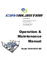
Operation &

Maintenance

Manual

Model 2040-ROV-M2 

CAVIDYNE, LLC

5077 Fruitville Rd.; Ste 109-157 
Sarasota, FL 34232 

Phone: (352) 275-5319

www.caviblaster.com

Summary of Contents for Caviblaster 2040-ROV-M2

Page 1: ...Operation Maintenance Manual Model 2040 ROV M2 CAVIDYNE LLC 5077 Fruitville Rd Ste 109 157 Sarasota FL 34232 Phone 352 275 5319 www caviblaster com ...

Page 2: ... entire manual carefully before use The CaviBlaster 2040 ROV M2 must only be operated and maintained by trained personnel This equipment generates high pressure water and is intended for underwater use only Serious personal injury or death may result from improper use Page 2 For more information please email sales cavidyne com or call 1 352 275 5319 ...

Page 3: ...et Up 13 5 0 OPERATION 14 5 1 Preparing the CaviBlaster for Operation 14 5 2 Startup of the CaviBlaster 15 5 3 Normal Operation 15 5 4 Adjusting the CaviBlaster for Maximum Performance 16 5 5 Recommendations for Effective Results 19 6 0 MAINTENANCE 21 6 1 Basic Preventive Maintenance Recommendations 22 6 3 Pump Service 22 6 4 Inspection Cleaning of Water Inlet Strainer 22 7 0 TROUBLESHOOTING 23 8 ...

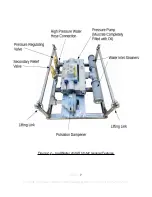
Page 4: ...tions 7 Figure 2 1 CaviBlaster 2040 ROV M2 General Features 12 Figure 4 1 Lifting Guidelines 18 Figure 5 2 Lance Position for Best Cleaning results 19 This space intentionally left blank Page 4 For more information please email sales cavidyne com or call 1 352 275 5319 ...

Page 5: ...Installation Environment Submersible Hydraulic Oil Flow Requirements See below Overall Unit Dimensions L x W x H 22 x 20 x 10 55 8 cm x 50 8 cm x 25 4 cm Maximum Pressure Hose Length 300 LF 100 meters of 3 4 1 9 cm diameter Power Unit Weight Dry 273 LBS 124 KG Hydraulic Power Unit must be capable of operating the water pressure pump at 1160 rpm and 55 HP Consult CaviDyne regarding the suitability ...

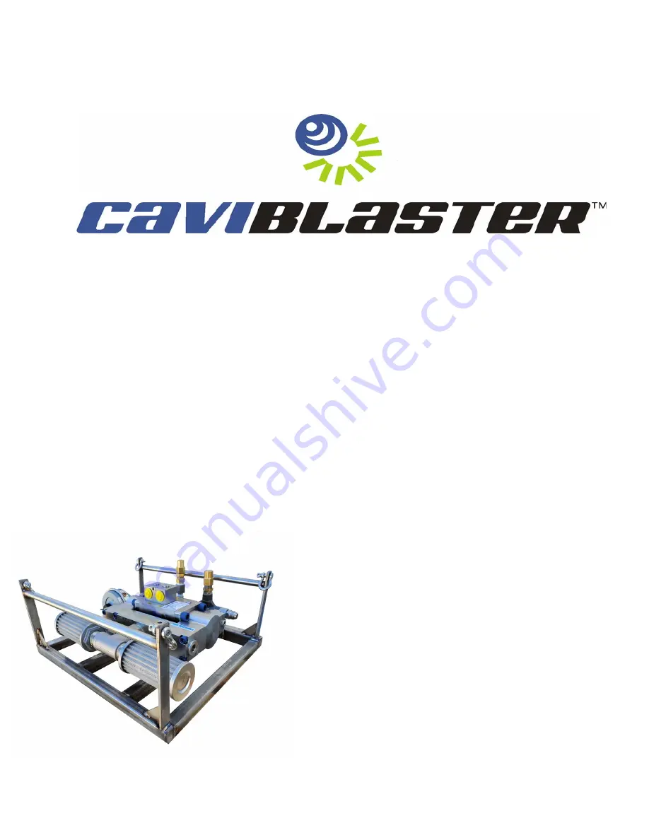
Page 6: ...ystem consists of a portable high pressure pumping unit designed for submersible ROV use and a high pressure cavitation lance connected to ROV manipulator with connecting high pressure hose The CaviBlaster 2040 ROV M2 power unit is a complete plug and play system built on a supporting platform that allows quick deployment and or installation of the unit Water is supplied directly from the unit ope...

Page 7: ...Figure 2 2 CaviBlaster 2040 ROV M2 General Features Page 7 For more information please email sales cavidyne com or call 1 352 275 5319 ...

Page 8: ...SECTION NAME will appear in italic caps The electronic version allows users to click on the section name or figure reference to jump to that section The words This space intentionally left blank will appear where there is more than 3 inches of white space EOS will appear above the page number on the last page of each section 2 3 Scope This manual covers installation operation and maintenance of th...

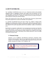
Page 9: ...tion in this manual for the correct procedures prior to any installation setup or maintenance work Note that the oil pressure compensator is not a pressurized component and therefore not a safety hazard It is open at one end and connected to the pressure pump oil chamber at the other end Its purpose is simply to balance the oil pressure in the water pressure pump with the unit s surrounding enviro...

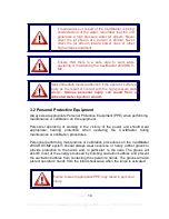
Page 10: ...nt PPE when performing maintenance or calibration on this equipment Personnel operating or working in the vicinity of the power unit should wear appropriate hearing protection when operating the CaviBlaster during maintenance or calibration procedures Personnel performing maintenance or calibration procedures on the CaviBlaster 2040 ROV M2 system should always wear neoprene or heavy rubber gloves ...

Page 11: ...parts with those recommended by or supplied by CaviDyne Any unapproved modifications will void the equipment warranty Unauthorized modification or part substitution can result in serious personal injury or property damage This space intentionally left blank Page 11 For more information please email sales cavidyne com or call 1 352 275 5319 Unauthorized replacement of any part may lead to catastrop...

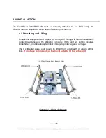
Page 12: ...ge is found immediately contact CaviDyne and the shipping company If the unit will not be installed immediately provide adequate indoor storage to protect against damage The CaviBlaster power unit should be lifted from underneath or via de Lifting links Do not use components of the CaviBlaster to lift the entire unit Figure 4 3 Lifting Guidelines Page 12 For more information please email sales cav...

Page 13: ...n on vibration mounts 10 It is important that there is no air trapped in the pump oil system 11 Connect hydraulic power unit hoses 12 Connect water pressure hose The CaviBlaster 2040 ROV M2 can be used with seawater but must be flushed and rinsed with fresh water after every use in seawater Failure to flush and rinse the power unit after use in seawater will result in increased wear and tear on co...

Page 14: ...diate use This should be completed after each use 1 Inspect the CaviBlaster power unit hoses JIC fittings and lance for any signs of damage 2 Inspect the water inlet strainer to ensure that it is not clogged See Figure 2 1 Clean if necessary 3 Check for proper pressure pump oil level See pump Owner s Manual found in the Appendix Add oil SAE 30 non detergent if necessary PUMP MUST BE COMPLETELY FIL...

Page 15: ...trol of water flow via the lance In the absence of a diver control of the power unit is accomplished by the ROV manipulator Should a problem develop with the control valve discontinue using the CaviBlaster until fixed Review the safety requirements for PPE and safe operation before proceeding 1 The ROV hydraulic system needs to be operating at a capacity that matches the water pressure pump requir...

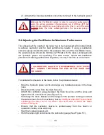
Page 16: ...e if cleaning performance degrades or every 3 months at a maximum To calibrate the pressure at the lance follow the procedure below Stop the hydraulic power unit to discharge any residual pressure in the hose lines Disconnect the lance from the main hose line Attach the calibration gauge between the main hose line and the lance and tighten the JIC connections See Figure 5 1 Submerge the lance Beca...

Page 17: ...ill decrease the pressure This space intentionally left blank Page 17 For more information please email sales cavidyne com or call 1 352 275 5319 DO NOT ADJUST THE PRESSURE AT THE LANCE TO MORE THAN 4 000 PSI 275 BAR HIGHER PRESSURE WILL NOT IMPROVE PEFORMANCE AND COULD RESULT IN SERIOUS DAMAGE TO THE PUMP HOSES ARE RATED FOR 4 000 PSI 275 BAR PRESSURES ABOVE 4 000 PSI 275 BAR COULD RESULT IN HOSE...

Page 18: ...Figure 5 1 Lance Pressure Calibration Page 18 For more information please email sales cavidyne com or call 1 352 275 5319 ...

Page 19: ...from the surface to be cleaned and at a 25 to 45 degree angle to the surface being cleaned See Figure 5 2 The ROV operator needs to observe the shape of the cavitating jet cone At greater depths the higher ambient pressure will cause the jet cone to be shorter The widest zone of the cone is the most efficient part of the cavitating jet Placing the nozzle closer than 2 inches 5 cm from the surface ...

Page 20: ...ure pump and relieve pressure in the system 2 It is now safe to remove the lance from the water 3 Flush the system and rinse the power unit with fresh water at the end of the day or work shift This space intentionally left blank EOS Page 20 For more information please email sales cavidyne com or call 1 352 275 5319 ...

Page 21: ...ed or approved by CaviDyne Use of any other parts may lead to equipment failure and severe personal injury CaviBlaster MUST BE FLUSHED AND RINSED WITH FRESH WATER AFTER EACH USE IN SEA WATER FAILURE TO FLUSH AND RINSE THE UNIT WILL RESULT IN PREMATURE WEAR AND TEAR ON THE COMPONENTS AND DECREASED SERVICE LIFE Failure to flush and rinse the unit can cause the pump valve s to stick in the open posit...

Page 22: ...ediately 2 The initial oil change is required after 50 hours of operation See pump manufacturer s literature in the Appendix for additional recommendations 6 3 Pump Service The high pressure water pump requires minimal maintenance The pump oil should be checked on a regular basis The pump crankcase should be COMPLETELY FILLED with SAE 30 viscosity non detergent oil See pump manufacturer s literatu...

Page 23: ... b Connect the hydraulic motor to a hydraulic power unit and start the hydraulic power unit Verify that the hydraulic power unit is delivering the correct RPM 1160 and HP 55 required to operate the water pressure pump c If water is leaking out of the hose fittings or connections replace the damaged component and securely tighten all connections d If water is leaking from the lance body contact Cav...

Page 24: ...Pump valve kit 31292 1 1 Pressure regulator optional CAT 7024 100 1 1 Regulating Unloader UB 402 1 1 Safety relieve valve CAT 9940 1 1 Oil pressure compensator 50MH52DBCSC All parts can be ordered from CAVIDYNE LLC 5077 Fruitville Rd Ste 109 157 Sarasota FL 34235 USA Phone 352 275 5319 Email support cavidyne com www caviblaster com EOS Page 24 For more information please email sales cavidyne com o...

Page 25: ...heet Pump Exploded View Pump Dimensions Pump Service Guide Pump Torque Specs CAT Pressure Regulator Model 7024 100 Valve Spec Sheet Udor Model UB 402 Regulating Unloader Valve Valve Spec Sheet Cavidyne Cross CAT Udor USA Warranties EOS Page 25 For more information please email sales cavidyne com or call 1 352 275 5319 ...

Reviews: