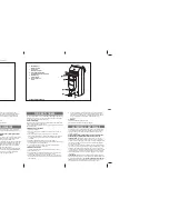
OUTPUT SHAFT ASSEMBLY
FOR MODEL T OPERATORS
K72-12508 (1/3 H.P. & 1/2 H.P.) OR
K72-12509 (3/4 H.P. & 1 H.P.)
To prevent possible SERIOUS INJURY or DEATH, disconnect
electric power to operator BEFORE installing.
ALL electrical connections MUST be made by a qualified
individual.
ITEM DESCRIPTION
QTY
1
Output shaft
1
2
Flange bearing
2
3
Sprocket 41B10 x 3/4 bore
(3/4 & 1 HP)
1
Sprocket 48B10 x 3/4 bore,
steel (1/3 & 1/2 HP)
1
4
Sprocket 41B32 x 3/4 bore
1
5
Sprocket 48B10 x 3/4 bore
1
6
Drive chain #41 x 47 pitches
1
7
Limit chain #48 x 33 pitches
1
8
Shim washer
2
9
Slotted spring pin 1/4" x 1-1/8"
2
10
Slotted spring pin 1/4" x 1-1/2"
1
11
Push ring 3/4" I.D.
1
12
Cotter Pin, 1/8 x 1-3/4"
2
PACKING LIST
© 2006, The Chamberlain Group Inc.
01-12502C
All Rights Reserved
NOTE: Refer to the owner’s manual provided with the operator for
all mounting and wiring instructions.
REMOVE EXISTING SHAFT ASSEMBLY
1. Disconnect power to the operator.
2. Remove the trolley drive chain.
3. Remove the reduction drive chain and the limits drive chain.
4. Remove the roll pin from the trolley drive sprocket.
5. Remove the push ring from the end of the output shaft.
6. Slide the output shaft out of the frame. The trolley drive
sprocket will slide along the shaft as it is removed.
7. Remove the existing flanged bearings from the frame.
INSTALL NEW OUTPUT SHAFT
1. Secure the reduction drive sprocket and the limit drive sprocket
to the shaft with the drive slotted spring pins provided. Install
cotter pin through the slotted spring pin for the drive sprocket
as illustrated.
2. Insert the flanged bearings into each side of the frame.
3. Insert the output shaft with the sprockets and shim washer in
place into the frame. Make sure to slide the trolley drive
sprocket on the shaft when passing through the frame.
4. Replace the final shim and secure the shaft in the frame with
the push on ring.
5. Secure the trolley drive sprocket to the shaft with slotted spring
pin. Install cotter pin through the slotted spring pin for the drive
sprocket as illustrated.
6. Replace the reduction drive chain and the limits drive chain.
7. Replace the trolley drive chain.
8. Restore power to the operator.
9. Adjust the open and close limits as needed for door travel.
9
12
5
6
10
4
1
11
2
2
7
8
3
8
9
12
END VIEW
For more information:
www.devancocanada.com
or call toll free at 855-931-3334


