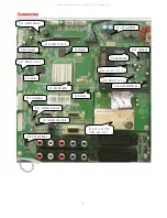
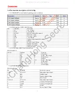
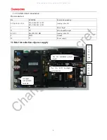
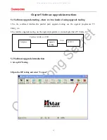
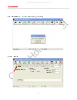
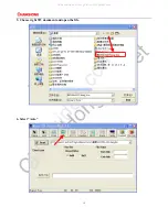
background image


LCD COLOUR TV 


MAINTENANCE MANUAL 


MODEL: LS18 CHASSIS

MSD308/309PX


Please read this manual carefully before maintenance 

All manuals and user guides at all-guides.com

all-guides.com

Summary of Contents for LS18

Page 1: ...0 LCD COLOUR TV MAINTENANCE MANUAL MODEL LS18 CHASSIS MSD308 309PX Please read this manual carefully before maintenance All manuals and user guides at all guides com a l l g u i d e s c o m...

Page 2: ...ystems mainboard interface definition and the waveform of key points 9 4 1 The chassis frame diagram 9 4 2 Power supply system 9 4 2 1 The composition and distribution of the TV power supply 9 4 2 2 P...

Page 3: ...e top when shutdown the machine 5 Please avoid the impact from the mobile phone to protect your TV 1 3 Storage notes 1 When stored for a long time please keep the temperature between 0 to 40 don t exp...

Page 4: ...d of the screen practicality of the batch orders aspect ratio 16 9 resolving ratio 1366 x768 visual area H x V 697 68m m H 392 25m m V display colour 16 7 million contrast 4000 1 brightness 450cd m vi...

Page 5: ...D net weight no accessory Kg 2 2 Introduction of terminals practicality photos YpbPr2 audio input SCART1 SCART2 HDMI1 input PC input RF input YpbPr1 input PC audio input YpbPr1 audio input HDMI2 input...

Page 6: ...conversion 3 U4 AT24C04BN SH T Store HDCP key 4 U52 AO4459 Power switch 5 U9 U15 W9751G6IB 25 DDR 6 U24 EN25Q64 104HIP Store program 7 U37 U38 LR1117 A 3 3 5V to 3 3V LDO 8 U39 LR1117 A 1 8 5V to 1 8V...

Page 7: ...R1117 A 1 8 U37 LR1117 A 3 3 U20 SN74LV4052 U18 AS7805DTR E1 U36 LR1117 A 2 5 U51 AP1534SG13 U11 STA335BW U10 DTI1 E4I1VH JUB2 891 170 U15 DDR U38 LR1117 A 3 3 U53 AO4803A U19 SGM330A YQS U17 SGM330A...

Page 8: ...put 3 2 3 EN25Q64 104HIP brief introduction Pin introduction Pin NO Pin Name I O Function 1 CS I Chip Select 2 DO O Serial Data Output 3 WP I White Protect 4 Vss Ground 5 DI I O Serial Data Input 6 CL...

Page 9: ...video I O 1 IN Select input 15 EN Switch enable input 4 7 9 12 DA DB DC DD Analog video I O 8 GND Ground 16 V Power supply 3 3 Brief introduction of power supply AC input AC100 240V 50 60HZ Use for L...

Page 10: ...pter mainly introduce the chassis frame diagram power supply system interface definition and each key point s wave shape 4 1 The chassis frame diagram 4 2 Power supply system Power board has two kinds...

Page 11: ...voltage adjustor on the mainboard item No U39 U51 U37 U38 U36 U18 output voltage 1 8V 1 32V 3 3V 2 5V 5V 3 3V 2 5V 5V PIN4 5 5V PIN9 10 12V 1 8V 1 32V 3 3V All manuals and user guides at all guides c...

Page 12: ...4 2 3 Interface definition ON OFF GND GND 5V 5V 5VSTB GND GND 12V 12V Used for USB POWER LED IR Backlight ON OFF KEY R R L L side AV s signal HDMI3 s signal All manuals and user guides at all guides c...

Page 13: ...12 4 3 The waveform of key points All manuals and user guides at all guides com...

Page 14: ...ort upgrade tooling use the upgrade programme TV Utility_4 4 2 Use interface upgrade tooling use the upgrade programme versions higher than TV Utility_4 4 5 2 Software upgrade introduction 1 Set up IS...

Page 15: ...14 3 Pls select OK once you connect the tooling successfully 4 Select Read All manuals and user guides at all guides com...

Page 16: ...15 5 Choose right SW document and open the file 6 Select Auto All manuals and user guides at all guides com a l l g u i d e s c o m...

Page 17: ...16 7 Select Run 8 The SW is updating All manuals and user guides at all guides com...

Page 18: ...17 9 Pls turn on the TV again once the SW is updated successfully All manuals and user guides at all guides com...

Page 19: ...picture no sound and indicator light is green Contrast brightness color and volume are all in the minimum value or TV is in mute mode Adjust the value of contrast brightness color and volume The sign...

Page 20: ...board part JUG6 693 241 Print plate JUG7 820 621 1 2 Side usb board part JUG6 693 224 Printplate JUG7 820 513 1 3 Mainboard part JUG6 690 711 Print plate JUG7 820 745 1 1 4 Remote receiving board part...

Page 21: ...erition key Pannel control Set pannel parameter Derition key Minmax value Set audio value Derition key Color temp Set color temp Derition key Picture position Set display position Derition key 2 Use t...

Page 22: ...not set it unless it is needed other setting items do not need setting 8 2 Setting method of factory menu C hoose set t i ng i t em Operators can choose setting item orderly with P and P key font hav...

Page 23: ...3 14329610 G005 1 14 R EN25Q64 104HIP 1 15 R RVVZ CH4 1600 ZH1 1 16 R AV JUG7 820 716 1 1 17 R JUG6 604 1199 7 1 18 19 R JUG6 604 1139 1 20 R JUG6 604 769 1 21 R JUG7 844 016 3 1 22 R VGA DBW 15A DSB4...

Page 24: ...54 R JA18AS 4MHZ 1 55 R TX SMT 5AW 1 56 R LR1117 A 3 3 AZ1117H 3 3TR LD1117S33T R AMS1117 3 3 LM1117MPX 3 3 NCP1117S T33T3 SPX1117M3 3 3 CW1117 3 3V 1 57 R LR1117 A 1 8 AZ1117H 1 8TRE1 LD1117S1 8TR AM...

Page 25: ...T1G LBAT54CLT1G T C 1 83 R FHBAT54C E BAT54CLT1G LBAT54CLT1G T C 1 84 R FHBAT54C E BAT54CLT1G LBAT54CLT1G 1 85 R 1206F105Z500NT T C 1 86 R 1206F105Z500NT T C 1 87 R RY21 2W 0 27 J RI 15 3 1 88 R CD110...

Page 26: ...53 AO4803A S2 1 G2 2 S1 3 G1 4 D2 8 D2 7 D1 6 D1 5 5V_USB0 CON2 CON5 2 0mm 1 2 3 4 5 LVDS3 2 CA58 100uF 16V MST Power supply ADJ OUT IN U36 AMS1117 ADJ 3 2 1 4 2 5VA 3 3VU R319 2 2k 5VA C1 0 1u R342 1...

Page 27: ...ADA_OUTP_CH 17 PAD_B_ODD 1 AE17 PAD_PWM0 AB25 PAD_PWM1 AB24 PAD_PWM2 E6 PAD_PWM3 D6 PAD_SAR0 J5 PAD_SAR1 G4 PAD_SPI_CK A2 PAD_SPI_DI B3 PAD_SPI_DO A3 DDCA_CK P6 DDCA_DA N6 PAD_DDCR_CK AA23 PAD_DDCR_DA...

Page 28: ...10k 1 8VA B_MVERF Close to DRAM 7 5 3 1 8 6 4 2 RP8 75RX4 R378 100R 7 5 3 1 8 6 4 2 RP19 75RX4 Close to MSD306 R379 100R Close to MSD306 MB_MCLKZ 7 5 3 1 8 6 4 2 RP9 75RX4 7 5 3 1 8 6 4 2 RP10 75RX4 M...

Page 29: ...V_B1 T_SDA IF_TV T_SCL 5V_B2 IF_AGC 2 T_RF_AGC IF_OUT 2 CON79 Pin16 2 00mm 16 15 14 13 12 11 10 9 8 7 6 5 4 3 2 1 IF_OUT 2 Title Size Document Number Rev Date Sheet of C 4 TEL 0755 26996895 FAX 0755 2...

Page 30: ...MCIA_CNT GND 1 D3 2 D4 3 D5 4 D6 5 D7 6 CE1 7 A10 8 OE 9 A11 10 A9 11 A8 12 A13 13 A14 14 WE 15 READY 16 VCC 17 VPP1 18 MIVAL 19 MICLK 20 A12 21 A7 22 A6 23 A5 24 A4 25 A3 26 A2 27 A1 28 A0 29 D0 30 D...

Page 31: ...DDCBSDA DDCBSCL DDCBSCL 2 R353 must pull up to HDMI_5V HOTPLUGB 2 HOTPLUGB CLKA CLKA 5VA U62 NC AZ1045 04SU I O1 1 GND 2 I O2 3 I O4 6 VDD 5 I O3 4 DA0 DA0 DD54 ESD 0603 RXB2P RXB2N RXB0N RXB1P RXBCL...

Page 32: ...DD53 ESD 0603 R129 75R R128 75R Q21 3904 1 2 3 DVD Y HD1 L HD2 R R277 100K R279 100K R228 100K R234 100K R281 100K SC2 C R284 100K R289 100K R285 100K R290 100K C111 2 2u HD2 L HD2 L C67 560p R300 100...

Page 33: ..._DMO R298 0R 2pF 2pF USB1_DPO USB1_DM 2 USB1_DP 2 DD64 ESD 0603 DD46 ESD 0603 DD44 ESD 0603 DD58 ESD 0603 close to USB connector 5V_USB1 F4 SMD1206P100TF_1A 1 2 5V_USB0 5V_USBO0 C144 0 1u F3 SMD1206P1...

Page 34: ...OUTR1 2 R 308 R 313 AUOUTL1 2 R 315 R 314 L128 15uH 2A R360 NC 0R MUTE Function L127 15uH 2A Power Ampifier C139 330u R271 0 47R 2W I2S_OUT_MCK VCC OP2 C24 2 2u R25 4 7K STBV_3 3V R37 4 7K C141 330u C...

Reviews: