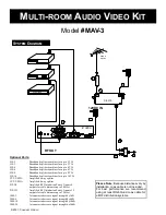
Step 1:
Connect the low-pass filter (model #3102-78) as far upstream as possible to the incoming cable or antenna line. This
will “clean up” the frequency range above channel 80 (antenna channel 29) to eliminate the potential for broadcast
interference with your new modulated channel. Optional filters (3102-60 and 3102-105) block channels 60 (antenna
channel 14) or 105 (antenna channel 49) and above. Please note: Channels 95-99 will not be affected by our filter.
Step 2:
Using a coaxial cable connect the output from the low-pass filter into the RF Input of the RF amplifier (model
C-0310). This will create a balance in signal strengths between the cable/antenna feed and the modulator output
before combining the two together. Also an amplifier prevents backfeed into the cable system.
Step 3:
Connect a coax cable (not included) from the C-0310 DC12V power input to the AC Adapter and plug the AC
Adapter into a 110V AC power outlet.
Step 4:
Connect a coax cable (not included) from the output of the C-0310 into one of the inputs on the broadband combiner
(model #HS-2T).
Step 5:
Connect each audio video source to the RF Modulator using RCA cables (not included).
Step 6:
Connect a coax cable from the RF output port to the second input port of the broadband combiner (model #HS-2T).
Step 7:
Plug the modulator 12VDC power transformer into a 110V AC power outlet.
Step 8:
Connect a coax cable from the combiner output to the input of a broadband splitter (not included) for distribution to
multiple televisions. Channel Vision has a variety of splitters available (models HS-2, HS-3, HS-4, HS-6, HS-8 or
HS-16) for distribution to multiple televisions. Any combination of splitters may be used to match the total outputs
required.
Modulator Setup:
Step M1:
While the unit is unplugged, choose the band and channel range you want to modulate to by selecting the appropriate
DIP switch settings on the back panel of the modulator. The modulator is pre-set for cable TV channels. Once you
have the DIP switches in place plug the unit into a 110V AC Power Outlet.
Step M2:
To change the modulator channel: push and hold the Select button for three seconds until the power LED on the front
of the unit begins to flash then press Up or Down to select a channel. Press the Select key again to lock the channel
into memory.
Step M3: Select a channel no lower than #84
as the low-pass filter (model #3102-78) has cleaned up the frequencies above
channel #80. Please Note: Channels 95-99 are not available.
Step M4:
The modulated channels should now be available at every television connected to the system.
© 2001, C
HANNEL
V
ISION
™
For more information on fine tuning your modulator please consult the RF Modulator operation manual.
S
TEP
-B
Y
-S
TEP
I
NSTALLATION
I
NSTRUCTIONS
234 F
ISCHER
A
VENUE
• C
OSTA
M
ESA
, CA 92626
(714) 424-6500 • (800) 840-0288 • F
AX
(714) 424-6510
www.channelvision.com • email: sales@channelvision.com
Model
#MAV-3
M
ULTI
-
ROOM
A
UDIO
V
IDEO
K
IT
REV
. 1/05


