Chenbro RB13804N4WFT, User Manual
The Chenbro RB13804N4WFT user manual is available for free download. Find detailed instructions on how to set up and use this product effectively, ensuring optimal performance. Download the manual from 88.208.23.73:8080 to access essential information and get the most out of your Chenbro RB13804N4WFT experience.
Share
Download


Reviews:
No comments
Related manuals for RB13804N4WFT

831010
Brand: Televes Pages: 50

Tiger Box 4U24
Brand: Tiger Technology Pages: 23
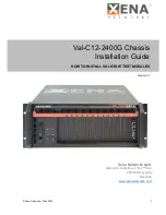
ValkyrieBay Val-C12-2400G
Brand: Xena Pages: 16

Racal Instruments 1264C
Brand: Eads Pages: 100

cDAQ-9138
Brand: National Instruments Pages: 6
ChromaFlex
Brand: ATX Pages: 90

Advanced Gateway 2330
Brand: Avaya Pages: 72

COREMAX M1 PROJECT GM
Brand: Grundig Pages: 98

CC800DW
Brand: Corsair Pages: 27


