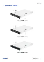
background image


RM238 Series   

Rackmount Chassis 

User Manual


January    2020    Version 1.1 


A document provides an overview of product features, functions, architecture, and support specifications. 

Summary of Contents for RM238 Series

Page 1: ...RM238 Series Rackmount Chassis User Manual January 2020 Version 1 1 A document provides an overview of product features functions architecture and support specifications...

Page 2: ...in trade This document contains information on products services and or processes in development All information provided here is subject to change without notice Contact your Chenbro representative...

Page 3: ...2 5 Slim ODD Removal and Installation 32 2 6 System Maintenance 33 2 7 Fan Assembly Removal and Installation 34 2 8 2 5 2 bay Drive Cage Installation Back Panel 37 2 9 Full height PCIe Card Installati...

Page 4: ...tion 8 x NVMe 16 x SATA SAS 15 Figure 18 24 x 2 5 front drive bay configuration 20 x NVMe 4 x SATA SAS 15 Figure 19 24 x 2 5 front drive bay configuration 24 x NVMe 15 Figure 20 Chassis dimensions 16...

Page 5: ...age installation back panel 37 Figure 56 Drive backplane installation back panel 38 Figure 57 Full height back panel bracket installation 39 Figure 58 Cards and brackets installation 39 Figure 59 Sing...

Page 6: ...ure 81 Backplane rear view 62 Figure 82 Backplane front view 63 Figure 83 Backplane rear view 64 Figure 84 Expander board rear view 65 Figure 85 Expander board front view 66 Figure 86 Backplane front...

Page 7: ...ction description 54 Table 16 Dip switch setting 55 Table 17 Fan setting for RM23812 55 Table 18 Solution and operating condition 56 Table 19 Backplane specifications 57 Table 20 Connector and pin hea...

Page 8: ...5 Hot swap 2 x 2 5 Internal 1 x Slim ODD RM23812 12 x 3 5 Hot swap RM23824 24 x 2 5 Hot swap 2 x 2 5 Hot swap Rear Option Storage Backplane RM23808 3 5 8 port 12Gbps Mini SAS HD RM23812 3 5 12 port 12...

Page 9: ...RM238 Series Product Overview 9 1 1 System Features Overview Figure 1 RM23808 overview Figure 2 RM23812 overview Figure 3 RM23824 overview...

Page 10: ...Figure 5 RM23812 major components overview Figure 6 RM23824 major components overview A Front Top Cover B Rear Top Cover C Label Embossing D Rear Top Cover Latch E Internal 2 5 HDD Bays F Fan Assembl...

Page 11: ...ies Product Overview 11 1 2 Front Panel Figure 7 RM23808 front panel Figure 8 RM23812 front panel Figure 9 RM23824 front panel A Front Control Panel B Storage Drive Bay C Info Tag D Rack Handles E Sli...

Page 12: ...Product Overview 12 1 3 Back Panel Figure 10 Back panel with single PSU Figure 11 Back panel with redundant PSU A 2U Single Power Supply B CRPS C I O Gasket D Low Profile Expansion Slots E 2 5 Hot sw...

Page 13: ...l Panel Figure 12 Front control panel Table 2 Front control panel Label ICON Indicator button or connector A PowerButton B UIDButton C ResetButton D USB3 0 E HDDActivityLED F SystemAlarmLED G LAN1 LAN...

Page 14: ...es Product Overview 14 1 5 Storage Configurations Figure 13 8 x 3 5 front drive bay configuration Figure 14 12 x 3 5 front drive bay configuration Figure 15 24 x 2 5 front drive bay configuration 24 x...

Page 15: ...ont drive bay configuration 4 x NVMe 20 x SATA SAS Figure 17 24 x 2 5 front drive bay configuration 8 x NVMe 16 x SATA SAS Figure 18 24 x 2 5 front drive bay configuration 20 x NVMe 4 x SATA SAS Figur...

Page 16: ...RM238 Series Product Overview 16 1 6 Chassis Dimensions Figure 20 Chassis dimensions Figure 21 Label embossing dimensions...

Page 17: ...il kit or misalignment of the server in the rack may result in failure of the rack rails causing damage to the system or personal injury Two persons to operate or the use of a mechanical assist tool t...

Page 18: ...2 RVI Operating HDD class Class 1 Highest performance reliability and data integrity Class 2 A second tier of performance reliability and data integrity HDD I O throughput degradation SPEC Pass Fail C...

Page 19: ...stem packaging information Part Number Single Bulk Form Factor mm Support level 387 23812 3300A0 Single 830 x 590 x 190 L5 NOTE The design of the inner packaging components does not prevent improper p...

Page 20: ...wap HDD or 2 5 HDD SSD RM23808 Up to 12 x 3 5 hot swap HDD or 2 5 HDD SSD RM23812 Up to 24 x 2 5 hot swap HDD SSD RM23824 1 x Slim ODD RM23808 2 x 2 5 hot swap SATA SSD 7 mm or 9 5 mm thickness or NVM...

Page 21: ...nstallation Figure 22 Rear top cover removal 1 Loosen two screws on the rear top cover 2 Pull the latch as shown to release the cover 3 Remove the cover Figure 23 Front top cover removal 1 Press two b...

Page 22: ...uide pins for both sides 2 Slide the cover toward the front panel until it is locked into place Figure 25 Rear top cover installation 1 Align the guide pins of the rear top cover with the grooves on t...

Page 23: ...l the HDD cage toward the front panel until it unlocks 3 Remove the HDD cage vertically Figure 27 HDD cage installation 1 Align the guide pins of the HDD cage with the grooves on the chassis base as s...

Page 24: ...hot swap HDD assembly removal 1 Press the tray button to release the lever as shown 2 Pull the HDD assembly out of the drive bay Figure 29 3 5 hot swap HDD assembly installation 1 With the lever open...

Page 25: ...own 2 Press out the HDD by your two thumbs NOTE Please operate this on a stable surface in case the HDD dropping unexpectedly 3 Lift the other side with your other fingers and release the HDD Figure 3...

Page 26: ...tallation 26 Figure 32 3 5 HDD removal screw type 1 Loosen four screws as shown 2 Take out the HDD from the tray Figure 33 3 5 HDD installation screw type 1 Align the HDD with the anchor point on the...

Page 27: ...val 1 Press the tray button and release the lever as shown 2 Pull the HDD assembly out of the drive bay Figure 35 2 5 hot swap HDD assembly installation 1 With the lever open insert the HDD assembly i...

Page 28: ...D tray as shown 2 Press out the HDD by your two thumbs NOTE Please operate this on a stable surface in case the HDD dropping unexpectedly 3 Lift the side with a concave slot by your other fingers and...

Page 29: ...igure 38 2 5 HDD removal screw type 1 Loosen four screws as shown 2 Take out the HDD from the tray Figure 39 2 5 HDD installation screw type 1 Align the front of the HDD with the anchor points on the...

Page 30: ...ray 2 Secure three screws as shown NOTE To ensure proper system airflow requirements all front drive bays are suggested to populate with a 3 5 drive tray where it is supposed to be installed with a 3...

Page 31: ...bly as shown 2 Remove it from the HDD cage 3 Detach the plastic bracket from HDD Figure 43 RM23808 internal 2 5 HDD installation 1 Attach the plastic bracket with the HDD by engaging four pins with th...

Page 32: ...removal 1 Press the latch to release the ODD assembly 2 Pull it out of the cage 3 Loosen the two screws to detach the plastic bracket Figure 45 RM23808 slim ODD installation 1 Secure the plastic brack...

Page 33: ...s as shown 2 Loosen the screws in the latches and firmly grab the rack handles on both sides 3 Pull the system out of the cabinet Figure 47 Installation of whole system into the rack 1 Firmly hold the...

Page 34: ...rews on both sides of the fan assembly 2 Disconnect all the fan connectors 3 Remove the fan assembly from the chassis base Figure 49 Fan assembly installation 1 Install the fan assembly in place by al...

Page 35: ...oval 1 Press the latch as shown and release the fan module from the fan cage vertically Figure 51 Fan module installation 1 Insert the fan module into the fan cage until it is secured into place NOTE...

Page 36: ...Components Removal and Installation 36 Figure 52 Air baffle removal 1 Pull out the air baffle from the fan cage Figure 53 Air baffle installation 1 Insert the air baffle into the fan cage until it is...

Page 37: ...m of the chassis and ensure the alignment of screw holes matched 2 Secure the bracket with two screws from the outside to the inside of the chassis Figure 55 Drive cage installation back panel 1 Inser...

Page 38: ...Removal and Installation 38 Figure 56 Drive backplane installation back panel 1 Attach the backplane to the rear of the drive cage as shown 2 Ensure the backplane firmly engaged with the cage 3 Secur...

Page 39: ...as shown Figure 58 Cards and brackets installation 3 Align the three screw holes of the riser card with T nails on the bracket and slide the riser card into place as shown 4 Secure the riser card with...

Page 40: ...d Removal Figure 59 Single 2U PSU installation 1 Install the PSU into the chassis and ensure the alignment of screw holes on the PSU the chassis base and the back panel matched 2 Secure the PSU with t...

Page 41: ...he cage as shown 2 Attach the PSU front bracket to the PSU cage and secure it by two screws 3 Install the PSU cage into the chassis and ensure the alignment of screw holes and brackets matched Figure...

Page 42: ...tion 42 Figure 62 CRPS module installation 1 Insert CRPS module into the PSU cage and push until it is secured into place Figure 63 CRPS module removal 1 Press the latch without release as shown 2 Pul...

Page 43: ...gure 64 Slide rail installation 1 384 23803 3300B0 1 Attach the inner rail to the chassis base while aligning the T pins on the side of the system with the slots on the inner rail Figure 65 Slide rail...

Page 44: ...emoval and Installation 44 Figure 66 Slide rail installation 3 384 23803 3300B0 3 Lift the latch as shown 4 Secure the inner rail with one screw Figure 67 Slide rail Installation 4 384 23803 3300B0 5...

Page 45: ...CON LED Color Behavior Condition A C Power LED N A Stay off Fault Blue Solid on Present B D Activity LED Green Stay on Access Red Solid on Failure 1Hz blink Rebuild 4Hz blink Locate NOTE The drive act...

Page 46: ...plane with docked expander board 8 x 2 5 Mini SAS HD passive backplane with 4 x tri mode SATA SAS NVMe ports 8 x 2 5 NVMe passive backplane All available SATA SAS backplanes include the following comm...

Page 47: ...r LED Off Fault Blue on Present Activity LED Green on Access Red on Failure Red 1Hz blink Rebuild Red 4Hz blink Locate EnvironmentMonitor Temperature sensor TMP75 U3 Connector 1 8 x SFF 8680 2 2 x Min...

Page 48: ...backplane includes two multi port Mini SAS HD connectors providing data signals for eight SAS SATA drives on the backplane A cable can be routed from matching connectors on the server board or add in...

Page 49: ...238 Series Backplane 49 Table 10 Fan setting for RM23808 DIP NC3 Mute pin JA1 JCK pins Fan ON PIN 5 6 OPEN PIN 4 6 SHORT 4 ON PIN 5 6 OPEN PIN 2 4 SHORT 2 ON PIN 5 6 SHORT N A No matter what status is...

Page 50: ...Blue on Present Activity LED Green on Access Red on Failure Red 1Hz blink Rebuild Red 4Hz blink Locate Environment Monitor Temperature sensor TMP75 U04 U05 Connector 1 12 x SFF 8680 2 3 x Mini SAS HD...

Page 51: ...the power supply B Mini SAS HD The backplane includes three multi port Mini SAS HD connectors providing data signals for twelve SATA SAS drives on the backplane A cable can be routed from matching co...

Page 52: ...2 Table 13 Dip switch setting PIN Number PIN Definition ON OFF 1 Fan1 EN DISABLE 2 Fan2 EN DISABLE 3 Fan3 EN DISABLE 4 Fan4 EN DISABLE 5 MBPWM EN DISABLE 6 TemperatureAlarm 55 65 7 ACCMode SGPIO HDD 8...

Page 53: ...Blue on Present Activity LED Green on Access Red on Failure Red 1Hz blink Rebuild Red 4Hz blink Locate Environment Monitor Temperature sensor TMP75 U7 U8 Connector 1 12 x SFF 8680 2 2 x Mini SAS HD 3...

Page 54: ...supply B Mini SAS HD The backplane includes two multi port Mini SAS HD connectors providing data signals for twelve SATA SAS drives on the backplane A cable can be routed from matching connectors on t...

Page 55: ...stem Fan Quantity 2 4 2 PWM EN DISABLE 3 Temperature Alarm 55 65 4 System Fan EN DISABLE 5 Buzzer EN DISABLE 6 SES MON EN DISABLE 7 8 I2C Address SET SET Table 17 Fan setting for RM23812 DIP JC5 Fan D...

Page 56: ...S Cache 7 0mm 2 X 35 3 9 5mm 2 X 35 3 NVMe SSD Cache 7 0mm 2 V 35 4 15 0mm 1 V 35 4 NOTE 1 2 port drive module is designed for OS and cache applications in which 7 0 mm 9 5 mm SATA SSD or 7 0 mm 15 0...

Page 57: ...rage device status Power LED Off Fault Blue on Present Activity LED Green on Access Red on Failure Red 1Hz blink Rebuild Red 4Hz blink Locate EnvironmentMonitor Temperature sensor TMP75 U2 Connector 1...

Page 58: ...kplane Power is routed to the backplane via a power cable harness from the power supply B SATA 7 pin The backplane includes two SATA 7 pin connectors providing data signals for two SATA SAS drives on...

Page 59: ...orage device status Power LED Off Fault Blue on Present Activity LED Green on Access Red on Failure Red 1Hz blink Rebuild Red 4Hz blink Locate EnvironmentMonitor Temperature sensor TMP75 U1 Connector...

Page 60: ...he backplane Power is routed to the backplane via a power cable harness from the power supply B OCuLink The backplane includes two OCuLink connectors providing data signals for two NVMe drives on the...

Page 61: ...us Power LED Off Fault Blue on Present Activity LED Green on Access Red on Failure Red 1Hz blink Rebuild Red 4Hz blink Locate EnvironmentMonitor Temperature sensor TMP75 U3 Connector 1 8 x SFF 8680 2...

Page 62: ...t SATA SAS drives on the backplane A cable can be routed from matching connectors on the server board or add in SATA SAS HBA cards C I2C The backplane includes two 4 pin connectors One is used as a ma...

Page 63: ...status Power LED Off Fault Blue on Present Activity LED Green on Access Red on Failure Red 1Hz blink Rebuild Red 4Hz blink Locate EnvironmentMonitor Temperature sensor TMP75 U1 U4 U10 U11 Connector 1...

Page 64: ...on Label Connector Description Drawing A Power The backplane includes two power connectors supplying 12V input to the backplane Power is routed to the backplane via a power cable harness from the powe...

Page 65: ...g to 16 port BP Hot Swap Yes allows users to replace storage devices online EnvironmentMonitor Temperature sensor TMP75 U3 Connector 1 5 x Mini SAS HD 2 1 x 8 pin ATX Mini Fit power connector for 12V...

Page 66: ...8 port BP and three for the connection to MB A cable can be routed from matching connectors on the add in SATA SAS HBA cards C I2C The backplane includes two 4 pin connectors used as a management inte...

Page 67: ...dicates storage device status Power LED Off Fault Blue on Present Activity LED Green on Access Red on Failure Red 1Hz blink Rebuild Red 4Hz blink Locate EnvironmentMonitor Temperature sensor TMP75 U02...

Page 68: ...port Mini SAS HD connectors providing data signals for eight SATA SAS drives on the backplane A cable can be routed from matching connectors on the server board or add in SATA SAS HBA cards C OCuLink...

Page 69: ...storage device status Power LED Off Fault Blue on Present Activity LED Green on Access Red on Failure Red 1Hz blink Rebuild Red 4Hz blink Locate EnvironmentMonitor Temperature sensor TMP75 U02 Connec...

Page 70: ...r is routed to the backplane via a power cable harness from the power supply B OCuLink The backplane includes eight OCuLink connectors providing data signals for eight NVMe drives on the backplane A c...

Page 71: ...ht to examine the DOA products If the damage of DOA products is caused by improper action as described above the customer will be liable for paying the related charge having occurred or paying the fee...

Reviews: