background image

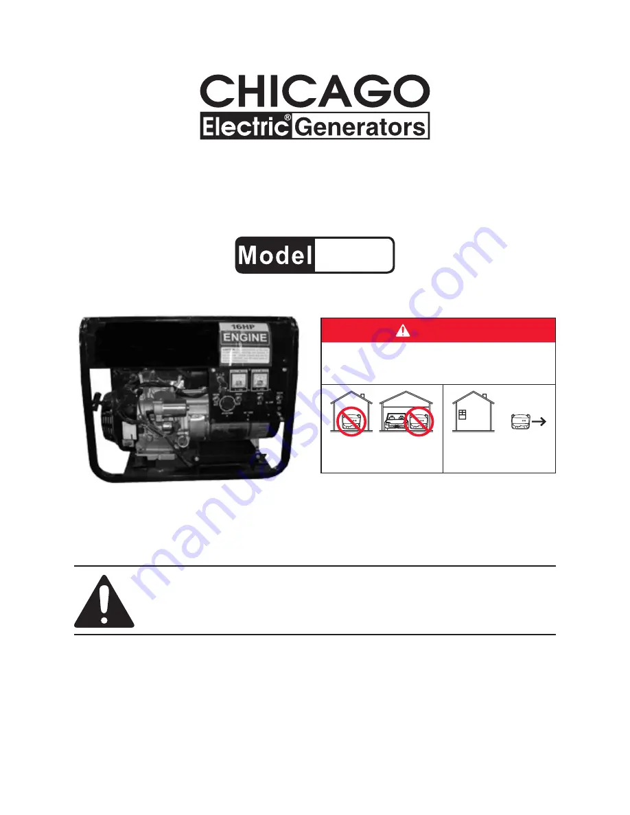
GENERATOR SET


16 HP - 7000/7500 WATTS

95960

SET uP, OPERATiNG, ANd SERviciNG iNSTRucTiONS


dANGER

using a generator indoors cAN KiLL YOu iN MiNuTES.
Generator exhaust contains carbon monoxide.  This is 

a poison you cannot see or smell.

NEvER use inside a home 

or garage, EvEN iF doors 

and windows are open.

Only use OuTSidE and 

far away from windows, 

doors, and vents.

distributed exclusively by Harbor Freight Tools

®

.

3491 Mission Oaks Blvd., Camarillo, CA 93011

visit our website at: http://www.harborfreight.com

 Read this material before using this product. 

Failure to do so can result in serious injury. 

SAvE THiS MANuAL.

Copyright

©

 2007 by Harbor Freight Tools

®

.  All rights reserved.  No portion of this manual or any artwork 

contained  herein  may  be  reproduced  in  any  shape  or  form  without  the  express  written  consent  of 

Harbor Freight Tools.  Diagrams within this manual may not be drawn proportionally.  Due to continuing 

improvements,  actual  product  may  differ  slightly  from  the  product  described  herein.   Tools  required  for 

assembly and service may not be included.

For technical questions or replacement parts, please call 1-800-444-3353.

Manual Revised 08i

Summary of Contents for 95960

Page 1: ...at http www harborfreight com Read this material before using this product Failure to do so can result in serious injury Save this manual Copyright 2007 by Harbor Freight Tools All rights reserved No portion of this manual or any artwork contained herein may be reproduced in any shape or form without the express written consent of Harbor Freight Tools Diagrams within this manual may not be drawn p...

Page 2: ...tdown Additional Features Locking ON OFF with 2 Keys Overall Dimensions 24 1 8 Long x 20 1 2 Wide x 24 1 2 High Net Weight 188 Pounds IMPORTANT This product requires oil and fuel to be added before starting Attempt ing to start the Engine without oil WILL ruin the Engine and void the warranty NOTE The Engine s carburetor may need to be adjusted by a qualified mechanic for efficient high altitude u...

Page 3: ...ed in the work area Personal Safety Stay alert Watch what you are doing and use common sense when operat 1 ing a power tool Do not use a power tool while tired or under the influence of drugs alcohol or medication A moment of inattention while operating power tools may result in serious personal injury Dress properly Do not wear loose clothing or jewelry Contain long hair 2 Keep your hair clothing...

Page 4: ...ands of untrained users Maintain tools with care Keep the Generator clean 5 Properly maintained tools are less likely to malfunction and are easier to control Do not use a damaged tool Tag damaged tools Do not use until repaired Check for misalignment or binding of moving parts breakage of parts and 6 any other condition that may affect the tool s operation If damaged have the tool serviced before...

Page 5: ...e work area Always use the Generator on a flat level surface 7 Make sure to keep hands fingers and feet away from all moving parts of the 8 Generator Keep all safety guards of the Generator in place and in proper working order 9 TOXIC FUMES FIRE AND EXPLOSION PRECAUTIONS This Generator is designed for outdoor use only Do not operate the Genera 1 tor in a closed area or in a poorly ventilated area ...

Page 6: ... Plug Wire from the Spark Plug Do not alter or adjust any part of the Generator or its Engine that is assem 2 bled and supplied by the manufacturer or distributor Always follow and complete scheduled Engine maintenance 3 CHEMICAL PRECAUTIONS Avoid contact with hot fuel oil exhaust fumes and solid surfaces 1 Avoid body contact with fuels oils and lubricants used in the Engine 2 If swallowed seek im...

Page 7: ... while standing in water 4 or on wet or soggy ground Do not touch electrically energized parts of the Generator and interconnecting 5 cables or conductors with any part of the body or with any non insulated conduc tive object Connect the Generator only to a load or electrical system 120 volt or 240 volt that 6 is compatible with the electrical characteristics and rated capacities of the Genera tor...

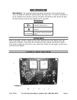
Page 8: ...ge of this manu al as soon as possible CONTROL PANEL FEATURES 2 3 5 5 5 9 8 10 10B VOLTMETER VOLTMETER 7 7 FIGURE A MISC PRECAUTION WARNING The warnings and precautions discussed in this manual cannot cover all possible conditions and situations that may occur It must be understood by the operator that common sense and caution are factors which cannot be built into this product but must be supplie...

Page 9: ... protect the unit from overloading One a Circuit Breaker controls the 3 Prong 120 volt Outlet Socket 8 One b Circuit Breaker controls the 3 Prong Twistlock 120 volt Outlet Socket 10 Two c Circuit Breakers control the 4 Prong Twistlock 240 120 volt Outlet Socket 10B One d In Line Circuit Breaker to protect the Engine s Starter 83A Should any of the four Circuit Breakers trip the Engine will automat...

Page 10: ...B BOLT WITH LOCK WASHER 46 NEGATIVE BATTERY CABLE POSITIVE BATTERY CABLE BATTERY GUARD PLATE 44 BATTERY TRAY 48 BATTERY BRACKET 47 12 VDC BATTERY NOT INCLUDED FIGURE B Connect the Engine s Positive Battery Cable RED to the Battery s positive 6 terminal Then connect the Engine s Negative Battery Cable BLACK to the Battery s negative terminal See Figure B TO ATTACH THE WHEEL ASSEMBLY With additional...

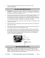
Page 11: ...re rain drainage or flood 3 waters can not reach it Generator placement should allow four feet of access to all sides for maintenance 4 and proper air cooling Place the Generator as close as possible to the electrical tools and equipment be 5 ing powered to reduce the length of extension cords To ground the Generator connect a 6 AWG grounding wire not included from 6 the Grounding Terminal 9 on th...

Page 12: ...op edge of the Dipstick Hole Then make sure to screw the Oil Dipstick back into its Dipstick Hole See Figure D FUEL TANK 31 FUEL TANK GAUGE FUEL TANK CAP 34 FUEL FILTER 32 FIGURE E 4 To fill the Fuel Tank 31 unscrew and remove the Fuel Tank Cap 34 Fill the Fuel Tank with mid to high octane unleaded gasoline Then replace the Fuel Tank Cap Thereafter check the Fuel Tank Gauge for the amount of unlea...

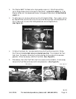
Page 13: ...o rewind slowly Then pull the Starter Handle with a rapid full arm stroke Allow the Rope to rewind slowly If necessary repeat this procedure until the Engine starts When the Engine starts slowly move the Choke Lever 21A to its 6 RUN position See Figure F IMPORTANT 7 Allow the Generator to run at no load for five minutes after each start up so that the Engine and Generator can stabilize TO CONNECT ...

Page 14: ...rator IMPORTANT 6 Failure to connect and operate appliances tools and equipment in this sequence can cause damage to the Generator appliances tools and equip ment and will void the Warranty of this Generator Once the Engine is running simply connect the 120 VAC appliances tools and 7 equipment into the 120 VAC Outlet Sockets 8 10 Also connect a 240 VAC ap pliance tool or equipment into the 240 VAC...

Page 15: ...nterior workings of the Gen erator ENGINE MAINTENANCE After the first 5 to 8 hours of use 1 Change the oil Then change the oil every 50 hours of use Change the oil every 25 hours of use when operating the Engine under a heavy load or in high temperatures PLUG 59A OIL DIPSTICK 65A FIGURE G 2 To change the oil remove the Plug 59A and allow the old oil to drain in a proper container Once drained repl...

Page 16: ...ght oil into the Element and squeeze the Element so oil reaches all parts of the Element See Figure H Use compressed air to clean the Air Element Separator 20A Then replace the 7 Air Element Separator Air Cleaner Element and Air Cleaner Cover 18A See Figure H Clean more often under dusty conditions or when airborne debris is present Re 8 place Air Cleaner parts if necessary See Figure H FIGURE I S...

Page 17: ... old fuel in the Fuel Tank may clog the Carburetor of the Engine and prevent it from starting until cleaned out Then make sure to store the unit in a clean dry safe location out of reach of children and other unauthorized people PLEASE READ THE FOLLOWING The manufacturer and or distributor has provided the parts list and assembly diagram in this manual as a reference tool only Neither the manufact...

Page 18: ...Page 18 SKU 95960 For technical questions please call 1 800 444 3353 TROUBLESHOOTING ...

Page 19: ...2 20 Cable Sheath 1 21 Carbon Brush 1 22 Bolt M10x1 25x265 1 23 Bolt M6x180 4 24 Bolt M5x20 4 25 Connection Board 1 26 Nut M5 4 27 Stator 1 28 Rotor 1 29 Cooling Fan 1 30 Heat Insulation Board Assy 1 31 Fuel Tank 1 32 Fuel Filter 1 33 Seal Ring 1 34 Fuel Tank Cap 1 37 Lock Washer Bolt M6x30 4 Part Description Qty 38 Spacer 4 39 Rub Washer 4 40 Bushing 4 41 Fuel Valve 1 42 Frame 1 43 Switch Box Cov...

Page 20: ...Page 20 SKU 95960 For technical questions please call 1 800 444 3353 ASSEMBLY DIAGRAM GENERATOR ...

Page 21: ... 2 32A Anti Wear Valve Stem Protector 2 33A Cylinder Head Cover Packing 1 34A Governor Spring 1 35A Bolt 1 36A High Tension Line 1 37A Ignition Coil 1 38A Nut Special 14mm 1 Part Description Qty 39A Starter Ratchet Spring 2 40A Starter Rope 1 41A Starter Handle 1 42A Recoil Starter 1 43A Spiral Spring 1 44A Starter Wheel 1 45A Circlip 1 46A Starter Ratchet 2 47A Friction Plate Screw 1 48A Cover 1 ...

Page 22: ...are not available individually as replacement parts Record Product s Serial Number Here Note If product has no serial number record month and year of purchase instead Part Description Qty 78A Compression Ring I 1 79A Compression Ring II 1 80A Oil Scraper Ring 1 81A Piston Pin 1 82A Piston Pin Circlip 1 Part Description Qty 83A Starter 1 84A Gear 1 85A Fuel Pipe 1 ...

Page 23: ...Page 23 SKU 95960 For technical questions please call 1 800 444 3353 ASSEMBLY DIAGRAM ENGINE ...

Page 24: ...Page 24 SKU 95960 For technical questions please call 1 800 444 3353 WIRING DIAGRAM REV 08g ...

Page 25: ...roduct at our election or we may elect to refund the purchase price if we cannot readily and quickly provide you with a replacement We will return re paired products at our expense but if we determine there is no defect or that the defect resulted from causes not within the scope of our warranty then you must bear the cost of returning the product This warranty gives you specific legal rights and ...

Page 26: ... a warranty station authorized by HFT For emissions warranty service contact the HFT Customer Service Department at 1 800 444 3353 3 Consequential Damages Coverage 4 Coverage under this warranty shall also extend to the failure of any engine components caused by the failure of any warranted part while it is still covered under this warranty 4 Coverage Exclusions 5 Warranty claims shall be filed in...

Page 27: ...pped ii Cold start enrichment system iii 2 Air Induction System Intake pipe manifold i Air cleaner ii 3 Ignition System Spark plug i Magneto ignition system ii 4 Catalyst System if so equipped Exhaust pipe stud i Muffler ii Catalytic converter if so equipped iii 5 Miscellaneous Items Used in Above Systems Vacuum temperature and time sensitive valves and switches i Hoses belts connectors and assemb...

Reviews: