background image

INST.No.INE-863B                                                                                                                KR2S

Communication Interface

Instruction Manual 


Graphic Recorder 

KR2S 

【Communication Interface】 


Instruction Manual 


Thank you for purchasing the KR2S series graphic recorder. 
Before using your new recorder, please be sure to read this instruction manual that will advise you on 
how to use the instrument correctly and safely and how to prevent problems. 


  Request to instrumentation engineers, constructors, and sale agents 


Make sure to deliver this instruction manual to the operator of this instrument. 
 

  Request to the operator of this instrument 


This instruction manual is necessary for maintenance, too. Keep this manual with care 
until the instrument is discarded. 

Summary of Contents for KR2S

Page 1: ...o read this instruction manual that will advise you on how to use the instrument correctly and safely and how to prevent problems Request to instrumentation engineers constructors and sale agents Make sure to deliver this instruction manual to the operator of this instrument Request to the operator of this instrument This instruction manual is necessary for maintenance too Keep this manual with ca...

Page 2: ...INST No INE 863B KR2S Communication Interface Instruction Manual ...

Page 3: ...al Manual No INE 862 3 SC8 10 Line Converter Manual No INE 39 For the personal computer PC you use refer to the manual attached to the PC Caution display The cautions to be observed for preventing the damage of this instrument and unexpected accidents are sorted by the following symbols according to their importance degrees for enabling operators to use this instrument safely Caution The nonobserv...

Page 4: ...tion precautions 13 6 1 1 Communications Terminals 13 6 1 2 Total extension of RS 485 communications cable is up to 1 2km 13 6 1 3 Take measures against noise 13 6 1 4 Crimp type terminals 14 6 1 5 Attach a termination resistor 14 6 1 6 Number of this unit connectable 14 6 2 Communications cables 15 6 2 1 Communications cables for RS 485 15 6 2 2 Communications cables for Ethernet 16 6 3 Communica...

Page 5: ...l setting values 40 8 2 Digital input data 41 8 3 Analog input data 44 8 3 1 Reading of instrument specifications 44 8 3 2 Reading of measured data 45 8 4 Analog setting values 48 8 4 1 Common parameters Date time High order communications etc 48 8 4 2 Setting parameters for each channel 51 8 4 3 Communications parameter 61 8 4 4 Low order communications parameter 81 8 4 5 Group parameter 85 8 4 6...

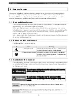
Page 6: ... this instruction manual to fully understand the cautions and basic operations 1 2 Labels on this instrument The following labels are used for safe use Label Name Meaning Alert symbol mark Indicates the location which should refer to the manual in order to prevent an electric shock and injury Protective conductor terminal A terminal is provided for connection to the protective conductor of the pow...

Page 7: ...nications interface However since these communications interfaces are characterized with serial communications it is easily connectable to a PC having the RS 232C communications interface by using an RS 232C RS 485 signal converting unit A line converter Model SC8 10 is available for RS 232C RS 485 signal conversion from CHINO 2 2 Ethernet Ethernet is the communications standard specified in IEEE8...

Page 8: ...ations protocol The MODBUS protocol has RTU mode and ASCII mode that can be selected by keys on the front of this unit or the communications By using the MODBUS protocol operation of measurement setting etc to instruments can be performed Ethernet interface performs by implementing the MODBUS protocol on TCP protocol packet MODBUS is a registered trademark of Schneider Automation Inc ...

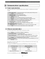
Page 9: ...ly Control signal not used Other External units precedence communications system 4 2 Ethernet communications Specifications of the Ethernet communications of this unit are as follows Media Ethernet 10BASE T 100BASE TX Communications mode Full duplex Half duplex Communications speed 10Mbps 10BASE T 100Mbps 100BASE TX However as the communications speed and the communications mode are automatically ...

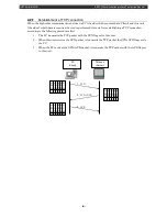
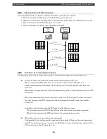
Page 10: ...ccording to the following procedures first 1 The PC transmits the TCP packet with the SYN flag set to this unit 2 When this unit receives the SYN packet it transmits the TCP packet the SYN ACK flags set to the PC 3 When the PC receives the SYN ACK packet it transmits the TCP packet with the ACK flag set to this unit U R G 0 A C K P S H R S T S Y N F I N 0 0 0 1 0 PC Client This unit Server 1 SYN 2...

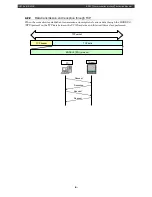
Page 11: ...tion through TCP When the connection is established transmission and reception of various data through the MODBUS RTU protocol on the TCP data between the PC Client side and this unit Server are performed PC This unit Request Response Request Request TCP header TCP data MODBUS RTU protocol TCP packet ...

Page 12: ...es When there is no response also to the transmission retry packet this unit disconnects the TCP connection When the communication partner requests to connect the TCP connection to this unit before this unit disconnect the TCP connection this unit transmits the RST packet to refuse the connection In addition this unit transmits the RST packet in the following cases When this unit receives the TCP ...

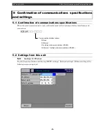
Page 13: ...ation is used confirm the model of this instrument before installations and connections KR2S Communication interface option N None E Ethernet R Low high order communications RS 485 G Ethernet low high order communications RS 485 5 2 Settings from this unit 5 2 1 Settings for Ethernet Tap the Operation button and then tap MENU settings Network settings Ethernet settings the following screen is disp...

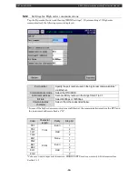
Page 14: ...ct the RTU ASCII Instrument address Set an arbitrary number in the range from 01 to 31 Bit rate Select 9600bps or 19200bps Communications character Select it from the codes listed below In case of the high order communications via Ethernet the communications mode is the RTU and the instrument address is fixed at 01 Code Character length Parity Stop bit 7E1 7 bits Even 1 7E2 2 7O1 Odd 1 7O2 2 8N1 8...

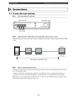
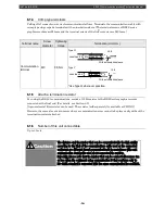
Page 15: ... 3 Take measures against noise Separate the communications cable from power lines and other communications lines more than 50 cm not to be affected by noise In addition when the communications using a PC or an Ethernet hub are performed depending on circumstances the hub communications ICs or the PC itself may be strongly affected by noise and failures may occur in communication with this unit In ...

Page 16: ...communication error cannot take place easily without the termination resistor attached 6 1 6 Number of this unit connectable Up to 31 sets Caution The distance and the number that can be communicated in the high quality according to the kind of the communications cable used or the connected equipment are different though communication IC in accordance with each communication standard is used about...

Page 17: ...s As the line converter has no SG terminal cut this wire to use Internal wiring Type code RZ LEC Cable length 1 to 99m to be specified 2 Connections between the KR2S recorder and the KR2S recorder Cable Crimp type ring terminals RS 485 with crimp type ring terminals Shape The cable consists of a twisted dual core CVVS wires with SG signal grounding wire at both ends As the line converter has no SG...

Page 18: ... PC and device When connecting a device to a PC directly one to one use a shielded crossover twisted pair cable commercially available STP cable 2 Connection between HUB and device multiple devices can be connected When connecting devices to a PC via HUB one to N use a shielded straight pair cable commercially available STP cable ...

Page 19: ...nverter and a personal computer and a control signal is not used Wiring process of connector differs from how the personal computer uses the control signal hence please understand your personal computer Turn the switch of RS422A RS485 to RS422A Avoid connecting SG line to FG terminal or ground terminal of the device Termination resistor 100Ω Device side Protocol converter SC8 10 1 2 3 4 5 6 7 8 Ca...

Page 20: ... connection 2 SYSMAC SA SB SG Avoid connecting SG line to FG terminal or ground terminal of the device Termination resistor 100Ω This recoder Termination resistor 100Ω SE3000 MEKSEC etc AL3000 etc SA SB SG RDA RDB SDA SDB SG Turn the switch of RS422A RS485 to RS422A Avoid connecting SG line to FG terminal or ground terminal of the device Termination resistor 100Ω This recorder Line converter SC8 1...

Page 21: ... one to one connection Example of connection between PC and HUB Ethernet devices one to N connection Device side HUB Straight twist pair cable with shield Max 100m PC side HUB Straight twist pair cable with shield Max 100m Straight twist pair cable with shield Max 100m Crossover twist pair cable with shield Max 100m DB1000 Device side PC side ...

Page 22: ... communications If devices or cables configuring the serial interface are removed or if the power is turned ON OFF during communications the communications may stop or an error may occur If this happens reset all the devices configuring the serial interface and restart the communications from the beginning 4 Transmit the next command after confirming that the communication drive is switched OFF In...

Page 23: ... 1 second When the data bit is 7 bits Parity bit None is not applicable 7 1 1 Transmission data The RTU mode is binary transmission The ASCII mode divides 8 bits binary of the RTU into higher 4 bits and lower 4 bits and converts into characters respectively 0 9 A F Ex RTU mode ASCII mode 67H 36H 6 89H 37H 7 ABH 38H 8 39H 9 41H A 42H B The RTU mode is half in the message length as compared to the A...

Page 24: ... maximum 1 second a master PC whose processing speed is comparatively slow can be used 7 3 Message configuration The MODBUS messages have the following configuration for both of the RTU mode and the ASCII mode Slave address Function code Data Error check 7 3 1 Slave address Slave addresses should be set in advance in a range of 1 31 The master usually communicates with 1 slave Only the slave corre...

Page 25: ... 16 bits 32763 to 32767 4 Analog input data Measurement data instrument specification information etc Numeric values in the range of 16 bits are outputted 7 3 3 Data part Data structures differ depending on the function codes In case of requests from the master they are configured by a code number relative numbers calculated from reference numbers mentioned hereafter of the target data for reading...

Page 26: ...on in messages is performed by relative numbers corresponding to the respective reference numbers Table 3 Reference numbers and relative numbers Data type Reference number Relative number MODBUS original Reference Digital setting value 1 to 10000 Reference number 1 Coil Digital input data 10001 to 20000 Reference number 10001 Input relay Analog input data 30001 to 40000 Reference number 30001 Inpu...

Page 27: ...n Measurement data 30001 to 30094 30101 to 30188 04 READ Para 8 3 Analog setting value Common parameter Date time Highordercommunications processing reset etc 40001 to 40098 03 READ 06 WRITE 16 WRITE Para 8 4 Setting parameter for each channel 40102 to 44500 Communications parameter 45001 to 45486 Lower communications parameter 45501 to 45544 Group parameter 46001 to 46500 Common parameter screen ...

Page 28: ...following calculation is performed for information from a slave address to the end of data 1 Initialization FFFFH of data of CRC 16 consider as X 2 Exclusive OR of data 1 and X EX OR X 3 1 bit shifting of X to the right X 4 For a carry existed A001H and EX OR are taken else go to 5 X 5 3 and 4 are repeated up to 8 time shifts 6 EX OR of the following data and X X 7 Same as 3 5 8 Repeating up to th...

Page 29: ... while scanf x usData 0 2 6 Taking exclusive OR of the CRC output result and the entered data usCrcData usData usCrcData CRC calculation processing 5 Repetition up to 8 bit shifts for iLoopCnt 0 iLoopCnt 8 iLoopCnt 4 Checking if there is a carry if usCrcData 0x0001 4 At a carry activated 3 1 bit shifting of the CRC output result to the right usCrcData usCrcData 1 4 Taking exclusive OR with A001H u...

Page 30: ...2H 30H 37H 46H 37H 7 3 6 Precautions at the time of data processing 1 As the measurement data and the decimal place are assigned to different numbers it is necessary to use both information at replaying the data 2 As each 1 data can be accessed changed precautions are necessary at the time of setting the associated data including Initialization process of the associated data due to change of a ran...

Page 31: ...er of bytes of data 3 Data part Starting relative number 100 00H 64H Number of data 2 00H 02H The measured data analog input data is stored in the reference number 30001 to 40000 Refer to Para 7 3 4 Table 3 By the reference table you will understand that the integer part of CH1 is stored in 30101 and the decimal place is stored in 30102 Refer to Para 7 5 and refer to Para 7 5 3 for reading of meas...

Page 32: ... to 7 3 5 Each data of the basic part is converted into the ASCII code In addition the LRC is converted into ASCII code and is attached to the basic part The start character of the message and CR and LF are added to the end Example In case of 02H 04H 00H 64H 00H 02H 30H and 27H 3AH 30H 32H 30H 34H 30H 30H 36H 34H 30H 30H 30H 32H 39H 34H 0DH 0AH CR 02H 04H 00H 64H 00H 02H 94H LRC LF ...

Page 33: ...xample Reading of 10 digital setting value reference numbers from 8 to 17 of the slave 2 Reference number 8 9 10 11 12 13 14 15 16 17 Data ON 0 is responded as no reference number exists Record ON RTU mode Master Instrument Master Instrument Slave address 02H Slave address 02H Function code 01H Function code 01H Start No H 00H Data pieces 02H End No L 07H First 8 data 00H Number of data H 00H Next...

Page 34: ...e number 10109 10110 10111 10112 10113 10114 10115 10116 Data ON OFF ON OFF Level 1 Level 2 Level 3 Level 4 0 is responded as no reference number exists CH1 Event activation status RTU mode Master Instrument Master Instrument Slave address 02H Slave address 02H Function code 02H Function code 02H Start No H 00H Data pieces 01H End No L 6CH First 8 data 05H Number of data H 00H CRC L 81H Number of ...

Page 35: ... 03H High limit value data H 03H CRC L B4H High limit value data L E8H CRC H 27H Decimal point data H 00H Decimal point data L 01H CRC L 74H CRC H 35H ASCII mode error check Error check The CRC L and the CRC H parts are as follows LRC 91H LRC 09H The start number Relative number is Reference number 40001 Decimal 103 40104 40001 Hexadecimal 67H The data pieces are the number of bytes of data It dif...

Page 36: ...n code 05H Setting value No H 00H Setting value No H 00H Setting value No L 13H Setting value No L 13H Setting status H FFH Setting status H FFH Setting status L 00H Setting status L 00H CRC L 7DH CRC L 7DH CRC H CCH CRC H CCH ASCII mode error check Error check The CRC L and the CRC H parts are as follows LRC E7H LRC E7H In case of a normal response the response is same as a command message The se...

Page 37: ...al Slave address 02H Slave address 02H Function code 06H Function code 06H Setting value No H 00H Setting value No H 00H Setting value No L 6EH Setting value No L 6EH Setting data H 00H Setting data H 00H Setting data L 14H Setting data L 14H CRC L E8H CRC L E8H CRC H 2BH CRC H 2BH ASCII mode error check Error check The CRC L and the CRC H parts are as follows LRC 76H LRC 76H In case of a normal r...

Page 38: ...a as it is is performed and the diagnosis code is fixed with 0000H Example Execution of Loop back test in the slave 2 RTU mode Master Instrument Instrument Master Normal Slave address 02H Slave address 02H Function code 08H Function code 08H Diagnosis code H Fixed 00H Diagnosis code H Fixed 00H Diagnosis code L 00H Diagnosis code L 00H Optional data Received data Optional data Received data CRC L ...

Page 39: ...RTU mode Master Instrument Instrument Master Normal Slave address 02H Slave address 02H Function code 10H Function code 10H Start No H 00H Start No H 00H End No L 67H End No L 67H Number of data H 00H Number of data H 00H Number of data L 03H Number of data L 03H Data pieces 06H CRC L 31H First dada H 00H CRC H E4H First data L 00H Second data H 03H Second data L E8H Third data H 00H Third data L ...

Page 40: ... RTU mode 28 bits hour or more ASCII mode 1 second or more 4 When the transmission parameter does not match 5 When the received message exceeds 512 bytes When the slave address is 0 in the writing function if there is no error in the message the message is performed but no response is performed 7 6 2 Error message response When the following error is detected in the message content not having any ...

Page 41: ... RTU Maximum 120 data ASCII 11H Out of setting value range Set error In case of any of the followings 1 For the range No etc not defined 2 When the setting value binary exceeds the range of 30000 to 30000 3 When the decimal point data exceeds the range of 0 to 3 4 When the RJ is set to internal for other than thermocouple input ranges 5 When the burnout is set to enable for other than thermocouple...

Page 42: ...are for the function code 05 Error code 01H 02H 03H 11H 12H 17 01 05 R W Record ON OFF 0 0000h Record OFF 1 FF00h Record ON The figures shown in parentheses are for the function code 05 Error code 01H 02H 03H 11H 12H 20 05 W Marker text writing 1 FF00h Marker text writing Writing of the text with the number specified by 48002 to the group specified by the analog setting value reference number 4800...

Page 43: ... in 2 bits 00 Measured data 01 Calculated data Error code 01H 02H 03H 10121 10122 10123 10124 02 R CH2 status 2 Status expression in 4 bits 0000 Normal data 0001 Over range 0010 Over range 0100 Burnout 1000 Invalid data Error code 01H 02H 03H 10125 10126 10127 10128 02 R CH2 alarm 1 activated CH2 alarm 2 activated CH2 alarm 3 activated CH2 alarm 4 activated 0 Not activated 1 Alarm activated Error ...

Page 44: ...R From CH14 event level 1 to CH14 event level 4 activated Same as CH1 10325 to 10336 02 R From CH15 event level 1 to CH15 event level 4 activated Same as CH1 10341 to 10352 02 R From CH16 event level 1 to CH16 event level 4 activated Same as CH1 10357 to 10368 02 R From CH17 event level 1 to CH17 event level 4 activated Same as CH1 10373 to 10384 02 R From CH18 event level 1 to CH18 event level 4 ...

Page 45: ...t level 4 activated Same as CH1 10645 to 10656 02 R From CH35 event level 1 to CH35 event level 4 activated Same as CH1 10661 to 10672 02 R From CH36 event level 1 to CH36 event level 4 activated Same as CH1 10677 to 10688 02 R From CH37 event level 1 to CH37 event level 4 activated Same as CH1 10693 to 10704 02 R From CH38 event level 1 to CH38 event level 4 activated Same as CH1 10709 to 10720 0...

Page 46: ...026 04 R External contact Optional external contact Enable 1 Disable 0 30079 04 R Serial number 1 2 ASCII 2 digits 30080 04 R Serial number 3 4 ASCII 2 digits 30081 04 R Serial number 5 6 ASCII 2 digits 30082 04 R Serial number 7 8 ASCII 2 digits 30083 04 R Serial number 9 10 ASCII 2 digits 30084 04 R Serial number 11 12 ASCII 2 digits 30085 04 R Serial number 13 14 ASCII 2 digits 30086 04 R Seria...

Page 47: ...al point status Same as CH1 30113 04 R CH7 measured data Same as CH1 30114 04 R CH7 decimal point status Same as CH1 30115 04 R CH8 measured data Same as CH1 30116 04 R CH8 decimal point status Same as CH1 30117 04 R CH9 measured data Same as CH1 30118 04 R CH9 decimal point status Same as CH1 30119 04 R CH10 measured data Same as CH1 30120 04 R CH10 decimal point status Same as CH1 30121 04 R CH1...

Page 48: ...H1 30158 04 R CH29 decimal point status Same as CH1 30159 04 R CH30 measured data Same as CH1 30160 04 R CH30 decimal point status Same as CH1 30161 04 R CH31 measured data Same as CH1 30162 04 R CH31 decimal point status Same as CH1 30163 04 R CH32 measured data Same as CH1 30164 04 R CH32 decimal point status Same as CH1 30165 04 R CH33 measured data Same as CH1 30166 04 R CH33 decimal point sta...

Page 49: ... sign 0 1 Exponent part sign sign 0 1 About the error 1023 Over High limit over flow 1022 Under Low limit over flow 1021 RJ RJ error 1020 BURN Burnout 1019 Cal Calculation error 1018 Other error 1017 Invalid data About the decimal point status information MSB 15 11 7 4 3 LSB 0 0 0 0 0 EV4 EV3 EV2 EV1 ERR BURN OF UF DP EV1 to 4 Each alarm status 0 Not activated 1 activated ERR Input part status 0 n...

Page 50: ...gits Error code 01H 02H 03H 11H 12H 40006 03 06 16 R W W Date time setting 11 12 Second ASCII 2 digits Error code 01H 02H 03H 11H 12H 40031 03 06 16 R W W High order transmission mode 0 RTU mode 1 ASCII mode Error code 01H 02H 03H 11H 12H 40032 03 06 16 R W W High order l instrument address 1 to 31 Error code 01H 02H 03H 11H 12H 40033 03 06 16 R W W High order transmission speed 3 9600bps 4 19200b...

Page 51: ...2 03 06 16 R W W Calculation reset at reference ASCII 2 digits 00 to 23 Error code 01H 02H 03H 11H 12H 40083 03 06 16 R W W Calculation reset for reference ASCII 2 digits 00 to 59 Error code 01H 02H 03H 11H 12H 40084 03 06 16 R W W Calculation reset at interval ASCII 2 digits 00 to 23 Error code 01H 02H 03H 11H 12H 40085 03 06 16 R W W Calculation reset for interval ASCII 2 digits 00 to 59 Error c...

Page 52: ...06 16 R W W Instrument name 9 10 ASCII 2 characters Shift JIS 1 character Error code 01H 02H 03H 11H 12H 40096 03 06 16 R W W Instrument name 11 12 ASCII 2 characters Shift JIS 1 character Error code 01H 02H 03H 11H 12H 40097 03 06 16 R W W Instrument name 13 14 ASCII 2 characters Shift JIS 1 character Error code 01H 02H 03H 11H 12H 40098 03 06 16 R W W Instrument name 15 16 ASCII 2 characters Shi...

Page 53: ...3H 09H 11H 12H 40105 03 06 16 R W W CH1 range high limit 30000 to 30000 Error code 01H 02H 03H 09H 11H 12H 40106 03 06 16 R W W CH1 range decimal point Range decimal place 0 to 3 Same decimal place for range high low lim Error code 01H 02H 03H 09H 11H 12H 40107 03 06 16 R W W CH1 scale low limit 30000 to 30000 Error code 01H 02H 03H 09H 11H 12H 40108 03 06 16 R W W CH1 scale high limit 30000 to 30...

Page 54: ...byte hour 0 to 24 Lower 1 byte minute 0 to 59 Error code 01H 02H 03H 09H 11H 12H 40119 03 06 16 R W W CH1 unit 1 2 ASCII Shift JIS 2 digit Error code 01H 02H 03H 09H 11H 12H 40120 03 06 16 R W W CH1 unit 3 4 ASCII Shift JIS 2 digit Error code 01H 02H 03H 09H 11H 12H 40121 03 06 16 R W W CH1 unit 5 6 ASCII Shift JIS 2 digit Error code 01H 02H 03H 09H 11H 12H 40122 03 06 16 R W W CH1 unit 7 ASCII 1 ...

Page 55: ...D Error code 01H 02H 03H 09H 11H 12H 40137 03 06 16 R W W CH1 reference channel 1 ASCII 2 digits Reference channel No at differential alarm 3031H 1 3032H 2 3033H 3 3938H 98 3939H 99 3A3 0H 100 3A31H 101 3B37H 127 3B38H 128 Error code 01H 02H 03H 09H 11H 12H 40139 03 06 16 R W W CH1 dead band 1 0 to 30000 The scale decimal point is used for the decimal place Error code 01H 02H 03H 09H 11H 12H 40140...

Page 56: ...03 06 16 R W W CH1 output relay 3 ASCII 2 digits 01 to Alarm output point 00H No setting Error code 01H 02H 03H 09H 11H 12H 40152 03 06 16 R W W CH1 AND OR 3 0 OR 1 AND Error code 01H 02H 03H 09H 11H 12H 40153 03 06 16 R W W CH1 reference channel 3 ASCII 2 digits Reference channel No at differential alarm 3031H 1 3032H 2 3033H 3 3938H 98 3939H 99 3A3 0H 100 3A31H 101 3B37H 127 3B38H 128 Error code...

Page 57: ... limit 30000 to 30000 Error code 01H 02H 03H 09H 11H 12H 40168 03 06 16 R W W CH1 display scale decimal point 0 to 3 Error code 01H 02H 03H 09H 11H 12H 40169 03 06 16 R W W CH1 display scale type 0 Standard 1 Logarithm Error code 01H 02H 03H 09H 11H 12H 40171 03 06 16 R W W CH1 range position Area belonged 0 to 3 At parallel scale 0 to 7 0 to 3 First zone 4 to 7 Second zone Error code 01H 02H 03H ...

Page 58: ...ormula 21 22 ASCII 2 digits Error code 01H 02H 03H 09H 11H 12H 40188 03 06 16 R W W CH1 calculation formula 23 24 ASCII 2 digits Error code 01H 02H 03H 09H 11H 12H 40189 03 06 16 R W W CH1 calculation formula 25 26 ASCII 2 digits Error code 01H 02H 03H 09H 11H 12H 40190 03 06 16 R W W CH1 calculation formula 27 28 ASCII 2 digits Error code 01H 02H 03H 09H 11H 12H 40191 03 06 16 R W W CH1 calculati...

Page 59: ... CH2 setting parameter Same as CH1 parameter 40102 to 40200 40302 to 40400 03 06 16 R W W CH3 setting parameter Same as CH1 parameter 40102 to 40200 40402 to 40500 03 06 16 R W W CH4 setting parameter Same as CH1 parameter 40102 to 40200 40502 to 40600 03 06 16 R W W CH5 setting parameter Same as CH1 parameter 40102 to 40200 40602 to 40700 03 06 16 R W W CH6 setting parameter Same as CH1 parameter...

Page 60: ...CH1 parameter 40102 to 40200 41802 to 41900 03 06 16 R W W CH18 setting parameter Same as CH1 parameter 40102 to 40200 41902 to 42000 03 06 16 R W W CH19 setting parameter Same as CH1 parameter 40102 to 40200 42002 to 42100 03 06 16 R W W CH20 setting parameter Same as CH1 parameter 40102 to 40200 42102 to 42200 03 06 16 R W W CH21 setting parameter Same as CH1 parameter 40102 to 40200 42202 to 42...

Page 61: ...3 06 16 R W W CH33 setting parameter Same as CH1 parameter 40102 to 40200 43402 to 43500 03 06 16 R W W CH34 setting parameter Same as CH1 parameter 40102 to 40200 43502 to 43600 03 06 16 R W W CH35 setting parameter Same as CH1 parameter 40102 to 40200 43602 to 43700 03 06 16 R W W CH36 setting parameter Same as CH1 parameter 40102 to 40200 43702 to 43800 03 06 16 R W W CH37 setting parameter Sam...

Page 62: ...ction Manual 60 Reference number Applied function code R W Content Detail 44302 to 44400 03 06 16 R W W CH43 setting parameter Same as CH1 parameter 40102 to 40200 44402 to 44500 03 06 16 R W W CH44 setting parameter Same as CH1 parameter 40102 to 40200 ...

Page 63: ...H 11H 12H 45010 03 06 16 R W W FTP client directory 1 2 ASCII 2 digits Error code 01H 02H 03H 09H 11H 12H 45011 03 06 16 R W W FTP client directory 3 4 ASCII 2 digits Error code 01H 02H 03H 09H 11H 12H 45012 03 06 16 R W W FTP client directory 5 6 ASCII 2 digits Error code 01H 02H 03H 09H 11H 12H 45013 03 06 16 R W W FTP client directory 7 8 ASCII 2 digits Error code 01H 02H 03H 09H 11H 12H 45014 ...

Page 64: ...09H 11H 12H 45026 03 06 16 R W W FTP Login user name client server 1 2 ASCII 2 digits Error code 01H 02H 03H 09H 11H 12H 45027 03 06 16 R W W FTP Login user name client server 3 4 ASCII 2 digits Error code 01H 02H 03H 09H 11H 12H 45028 03 06 16 R W W FTP Login user name client server 5 6 ASCII 2 digits Error code 01H 02H 03H 09H 11H 12H 45029 03 06 16 R W W FTP Login user name client server 7 8 AS...

Page 65: ...erver 31 32 ASCII 2 digits Error code 01H 02H 03H 09H 11H 12H 45042 03 06 16 R W W FTP Login password client server 1 2 ASCII 2 digits Error code 01H 02H 03H 09H 11H 12H 45043 03 06 16 R W W FTP Login password client server 3 4 ASCII 2 digits Error code 01H 02H 03H 09H 11H 12H 45044 03 06 16 R W W FTP Login password client server 5 6 ASCII 2 digits Error code 01H 02H 03H 09H 11H 12H 45045 03 06 16...

Page 66: ...de 01H 02H 03H 09H 11H 12H 45057 03 06 16 R W W FTP Login password client server 31 32 ASCII 2 digits Error code 01H 02H 03H 09H 11H 12H 45058 03 06 16 R W W FTP client PASV mode 0 OFF 1 ON Error code 01H 02H 03H 09H 11H 12H 45059 03 06 16 R W W FTP client Auto transfer 0 OFF 1 ON Error code 01H 02H 03H 09H 11H 12H 45060 03 06 16 R W W FTP client Retry mode 0 OFF 1 ON Error code 01H 02H 03H 09H 11...

Page 67: ...24 ASCII 2 digits Error code 01H 02H 03H 09H 11H 12H 45083 03 06 16 R W W FTP server address 25 26 ASCII 2 digits Error code 01H 02H 03H 09H 11H 12H 45084 03 06 16 R W W FTP server address 27 28 ASCII 2 digits Error code 01H 02H 03H 09H 11H 12H 45085 03 06 16 R W W FTP server address 29 30 ASCII 2 digits Error code 01H 02H 03H 09H 11H 12H 45086 03 06 16 R W W FTP server address 31 32 ASCII 2 digit...

Page 68: ...for server 23 24 ASCII 2 digits Error code 01H 02H 03H 09H 11H 12H 45103 03 06 16 R W W Login user name for server 25 26 ASCII 2 digits Error code 01H 02H 03H 09H 11H 12H 45104 03 06 16 R W W Login user name for server 27 28 ASCII 2 digits Error code 01H 02H 03H 09H 11H 12H 45105 03 06 16 R W W Login user name for server 29 30 ASCII 2 digits Error code 01H 02H 03H 09H 11H 12H 45106 03 06 16 R W W ...

Page 69: ... server 25 26 ASCII 2 digits Error code 01H 02H 03H 09H 11H 12H 45124 03 06 16 R W W Login password for server 27 28 ASCII 2 digits Error code 01H 02H 03H 09H 11H 12H 45125 03 06 16 R W W Login password for server 29 30 ASCII 2 digits Error code 01H 02H 03H 09H 11H 12H 45126 03 06 16 R W W Login password for server 31 32 ASCII 2 digits Error code 01H 02H 03H 09H 11H 12H 45141 03 06 16 R W W E mail...

Page 70: ...5141 to 45144 45165 to 45168 03 06 16 R W W E mail transfer condition 7 Same as E mail transfer condition 1 45141 to 45144 45169 to 45172 03 06 16 R W W E mail transfer condition 8 Same as E mail transfer condition 1 45141 to 45144 45181 03 06 16 R W W E mail transfer address 1 1 2 ASCII 2 digits Error code 01H 02H 03H 09H 11H 12H 45182 03 06 16 R W W E mail transfer address 1 3 4 ASCII 2 digits E...

Page 71: ... 29 30 ASCII 2 digits Error code 01H 02H 03H 09H 11H 12H 45196 03 06 16 R W W E mail transfer address 1 31 32 ASCII 2 digits Error code 01H 02H 03H 09H 11H 12H 45197 to 45212 03 06 16 R W W E mail transfer address 2 Same as E mail address 1 45181 to 45196 45213 to 45228 03 06 16 R W W E mail transfer address 3 Same as E mail address 1 45181 to 45196 45229 to 45244 03 06 16 R W W E mail transfer ad...

Page 72: ...H 45316 03 06 16 R W W E mail attached data CH6 Bit correspondence Bit 0 Address 1 to Bit 7 Address 8 0 Not attached 1 Attached Error code 01H 02H 03H 09H 11H 12H 45317 03 06 16 R W W E mail attached data CH7 Bit correspondence Bit 0 Address 1 to Bit 7 Address 8 0 Not attached 1 Attached Error code 01H 02H 03H 09H 11H 12H 45318 03 06 16 R W W E mail attached data CH8 Bit correspondence Bit 0 Addre...

Page 73: ...H 45326 03 06 16 R W W E mail attached data CH16 Bit correspondence Bit 0 Address 1 to Bit 7 Address 8 0 Not attached 1 Attached Error code 01H 02H 03H 09H 11H 12H 45327 03 06 16 R W W E mail attached data CH17 Bit correspondence Bit 0 Address 1 to Bit 7 Address 8 0 Not attached 1 Attached Error code 01H 02H 03H 09H 11H 12H 45328 03 06 16 R W W E mail attached data CH18 Bit correspondence Bit 0 Ad...

Page 74: ...H 45336 03 06 16 R W W E mail attached data CH26 Bit correspondence Bit 0 Address 1 to Bit 7 Address 8 0 Not attached 1 Attached Error code 01H 02H 03H 09H 11H 12H 45337 03 06 16 R W W E mail attached data CH27 Bit correspondence Bit 0 Address 1 to Bit 7 Address 8 0 Not attached 1 Attached Error code 01H 02H 03H 09H 11H 12H 45338 03 06 16 R W W E mail attached data CH28 Bit correspondence Bit 0 Ad...

Page 75: ...H 45346 03 06 16 R W W E mail attached data CH36 Bit correspondence Bit 0 Address 1 to Bit 7 Address 8 0 Not attached 1 Attached Error code 01H 02H 03H 09H 11H 12H 45347 03 06 16 R W W E mail attached data CH37 Bit correspondence Bit 0 Address 1 to Bit 7 Address 8 0 Not attached 1 Attached Error code 01H 02H 03H 09H 11H 12H 45348 03 06 16 R W W E mail attached data CH38 Bit correspondence Bit 0 Ad...

Page 76: ... 11H 12H 45362 03 06 16 R W W POP3 address3 4 ASCII 2 digits Error code 01H 02H 03H 09H 11H 12H 45363 03 06 16 R W W POP3 address5 6 ASCII 2 digits Error code 01H 02H 03H 09H 11H 12H 45364 03 06 16 R W W POP3 address7 8 ASCII 2 digits Error code 01H 02H 03H 09H 11H 12H 45365 03 06 16 R W W POP3 address9 10 ASCII 2 digits Error code 01H 02H 03H 09H 11H 12H 45366 03 06 16 R W W POP3 address11 12 ASC...

Page 77: ...3 06 16 R W W SMTPaddress3 4 ASCII 2 digits Error code 01H 02H 03H 09H 11H 12H 45383 03 06 16 R W W SMTPaddress5 6 ASCII 2 digits Error code 01H 02H 03H 09H 11H 12H 45384 03 06 16 R W W SMTPaddress7 8 ASCII 2 digits Error code 01H 02H 03H 09H 11H 12H 45385 03 06 16 R W W SMTPaddress9 10 ASCII 2 digits Error code 01H 02H 03H 09H 11H 12H 45386 03 06 16 R W W SMTPaddress11 12 ASCII 2 digits Error cod...

Page 78: ... W Senderaddress3 4 ASCII 2 digits Error code 01H 02H 03H 09H 11H 12H 45403 03 06 16 R W W Senderaddress5 6 ASCII 2 digits Error code 01H 02H 03H 09H 11H 12H 45404 03 06 16 R W W Senderaddress7 8 ASCII 2 digits Error code 01H 02H 03H 09H 11H 12H 45405 03 06 16 R W W Senderaddress9 10 ASCII 2 digits Error code 01H 02H 03H 09H 11H 12H 45406 03 06 16 R W W Senderaddress11 12 ASCII 2 digits Error code...

Page 79: ...6 R W W Mail account 3 4 ASCII 2 digits Error code 01H 02H 03H 09H 11H 12H 45423 03 06 16 R W W Mail account 5 6 ASCII 2 digits Error code 01H 02H 03H 09H 11H 12H 45424 03 06 16 R W W Mail account 7 8 ASCII 2 digits Error code 01H 02H 03H 09H 11H 12H 45425 03 06 16 R W W Mail account 9 10 ASCII 2 digits Error code 01H 02H 03H 09H 11H 12H 45426 03 06 16 R W W Mail account 11 12 ASCII 2 digits Error...

Page 80: ... W Mail password 3 4 ASCII 2 digits Error code 01H 02H 03H 09H 11H 12H 45443 03 06 16 R W W Mail password 5 6 ASCII 2 digits Error code 01H 02H 03H 09H 11H 12H 45444 03 06 16 R W W Mail password 7 8 ASCII 2 digits Error code 01H 02H 03H 09H 11H 12H 45445 03 06 16 R W W Mail password 9 10 ASCII 2 digits Error code 01H 02H 03H 09H 11H 12H 45446 03 06 16 R W W Mail password 11 12 ASCII 2 digits Error...

Page 81: ...er IP address 1 2 Higher 16 bits Error code 01H 02H 03H 09H 11H 12H 45463 03 06 16 R W W DNS primary server IP address 3 4 Higher 16 bits Error code 01H 02H 03H 09H 11H 12H 45464 03 06 16 R W W DNSsecondaryserver IP address 1 2 Higher 16 bits Error code 01H 02H 03H 09H 11H 12H 45465 03 06 16 R W W DNSsecondaryserver IP address 3 4 Higher 16 bits Error code 01H 02H 03H 09H 11H 12H 45466 03 06 16 R ...

Page 82: ...3 24 Higher 16 bits Error code 01H 02H 03H 09H 11H 12H 45479 03 06 16 R W W SNTP server 25 26 Higher 16 bits Error code 01H 02H 03H 09H 11H 12H 45480 03 06 16 R W W SNTP server 27 28 Higher 16 bits Error code 01H 02H 03H 09H 11H 12H 45481 03 06 16 R W W SNTP server 29 30 Higher 16 bits Error code 01H 02H 03H 09H 11H 12H 45482 03 06 16 R W W SNTP server 31 32 Higher 16 bits Error code 01H 02H 03H 0...

Page 83: ...nstryments number Lower 1 byte channel number 1 200 Error code 01H 02H 03H 09H 11H 12H 45506 03 06 16 R W W Low order communication registration instruments number channel number6 Higher 1 byte 0 No setting 1 5 instryments number Lower 1 byte channel number 1 200 Error code 01H 02H 03H 09H 11H 12H 45507 03 06 16 R W W Low order communication registration instruments number channel number7 Higher 1...

Page 84: ...stration instruments number channel number17 Higher 1 byte 0 No setting 1 5 instryments number Lower 1 byte channel number 1 200 Error code 01H 02H 03H 09H 11H 12H 45518 03 06 16 R W W Low order communication registration instruments number channel number18 Higher 1 byte 0 No setting 1 5 instryments number Lower 1 byte channel number 1 200 Error code 01H 02H 03H 09H 11H 12H 45519 03 06 16 R W W Lo...

Page 85: ...stration instruments number channel number29 Higher 1 byte 0 No setting 1 5 instryments number Lower 1 byte channel number 1 200 Error code 01H 02H 03H 09H 11H 12H 45530 03 06 16 R W W Low order communication registration instruments number channel number30 Higher 1 byte 0 No setting 1 5 instryments number Lower 1 byte channel number 1 200 Error code 01H 02H 03H 09H 11H 12H 45531 03 06 16 R W W Lo...

Page 86: ...e channel number 1 200 Error code 01H 02H 03H 09H 11H 12H 45540 03 06 16 R W W Low order communication registration instruments number channel number40 Higher 1 byte 0 No setting 1 5 instryments number Lower 1 byte channel number 1 200 Error code 01H 02H 03H 09H 11H 12H 45541 03 06 16 R W W Low order communication registration instruments number channel number41 Higher 1 byte 0 No setting 1 5 inst...

Page 87: ...hift JIS 2 digits Error code 01H 02H 03H 09H 11H 12H 46008 03 06 16 R W W Group 1 Display group name 15 16 ASCII Shift JIS 2 digits Error code 01H 02H 03H 09H 11H 12H 46011 03 06 16 R W W Group 1 Display channel allocaton Display_No ndisplay Trend line diameter 1 Bit 0 to 7 Display channel allocation 1 to Number of recording points 0 Not set Bit 8 to 10 Trend line diameter 0 1 1 2 2 3 3 4 4 5 Bit ...

Page 88: ...1H 12H 46017 03 06 16 R W W Group 1 Display channel allocaton Display_No ndisplay Trend line diameter 7 Bit 0 to 7 Display channel allocation 1 to Number of recording points 0 Not set Bit 8 to 10 Trend line diameter 0 1 1 2 2 3 3 4 4 5 Bit 12 Display_Nondisplay 0 Nondisplay 1 Display Error code 01H 02H 03H 09H 11H 12H 46018 03 06 16 R W W Group 1 Display channel allocaton Display_No ndisplay Trend...

Page 89: ...1H 12H 46024 03 06 16 R W W Group 1 Display channel allocaton Display_No ndisplay Trend line diameter 14 Bit 0 to 7 Display channel allocation 1 to Number of recording points 0 Not set Bit 8 to 10 Trend line diameter 0 1 1 2 2 3 3 4 4 5 Bit 12 Display_Nondisplay 0 Nondisplay 1 Display Error code 01H 02H 03H 09H 11H 12H 46025 03 06 16 R W W Group 1 Display channel allocaton Display_No ndisplay Tren...

Page 90: ...1H 12H 46031 03 06 16 R W W Group 1 Display channel allocaton Display_No ndisplay Trend line diameter 21 Bit 0 to 7 Display channel allocation 1 to Number of recording points 0 Not set Bit 8 to 10 Trend line diameter 0 1 1 2 2 3 3 4 4 5 Bit 12 Display_Nondisplay 0 Nondisplay 1 Display Error code 01H 02H 03H 09H 11H 12H 46032 03 06 16 R W W Group 1 Display channel allocaton Display_No ndisplay Tren...

Page 91: ...1H 12H 46038 03 06 16 R W W Group 1 Display channel allocaton Display_No ndisplay Trend line diameter 28 Bit 0 to 7 Display channel allocation 1 to Number of recording points 0 Not set Bit 8 to 10 Trend line diameter 0 1 1 2 2 3 3 4 4 5 Bit 12 Display_Nondisplay 0 Nondisplay 1 Display Error code 01H 02H 03H 09H 11H 12H 46039 03 06 16 R W W Group 1 Display channel allocaton Display_No ndisplay Tren...

Page 92: ...1H 12H 46045 03 06 16 R W W Group 1 Display channel allocaton Display_No ndisplay Trend line diameter 35 Bit 0 to 7 Display channel allocation 1 to Number of recording points 0 Not set Bit 8 to 10 Trend line diameter 0 1 1 2 2 3 3 4 4 5 Bit 12 Display_Nondisplay 0 Nondisplay 1 Display Error code 01H 02H 03H 09H 11H 12H 46046 03 06 16 R W W Group 1 Display channel allocaton Display_No ndisplay Tren...

Page 93: ...ndisplay 1 Display Error code 01H 02H 03H 09H 11H 12H 46052 03 06 16 R W W Group 1 Display channel allocaton Display_No ndisplay Trend line diameter 42 Bit 0 to 7 Display channel allocation 1 to Number of recording points 0 Not set Bit 8 to 10 Trend line diameter 0 1 1 2 2 3 3 4 4 5 Bit 12 Display_Nondisplay 0 Nondisplay 1 Display Error code 01H 02H 03H 09H 11H 12H 46053 03 06 16 R W W Group 1 Dis...

Page 94: ... 16 R W W Group 1 Trip line thickness 3 0 1 1 2 2 3 3 4 4 5 Error code 01H 02H 03H 09H 11H 12H 46070 03 06 16 R W W Group 1 Trip line position 4 1 to 99 0 None Error code 01H 02H 03H 09H 11H 12H 46071 03 06 16 R W W Group 1 Trip line color 4 1to 48 Error code 01H 02H 03H 09H 11H 12H 46072 03 06 16 R W W Group 1 Trip line thickness 4 0 1 1 2 2 3 3 4 4 5 Error code 01H 02H 03H 09H 11H 12H 46081 03 0...

Page 95: ...1H 12H 46086 03 06 16 R W W Group 1 Display channel allocaton Display_No ndisplay Trend line diameter 50 Bit 0 to 7 Display channel allocation 1 to Number of recording points 0 Not set Bit 8 to 10 Trend line diameter 0 1 1 2 2 3 3 4 4 5 Bit 12 Display_Nondisplay 0 Nondisplay 1 Display Error code 01H 02H 03H 09H 11H 12H 46087 03 06 16 R W W Group 1 Display channel allocaton Display_No ndisplay Tren...

Page 96: ...ot set Bit 8 to 10 Trend line diameter 0 1 1 2 2 3 3 4 4 5 Bit 12 Display_Nondisplay 0 Nondisplay 1 Display Error code 01H 02H 03H 09H 11H 12H 46092 03 06 16 R W W Group 1 Display channel allocaton Display_No ndisplay Trend line diameter 56 Bit 0 to 7 Display channel allocation 1 to Number of recording points 0 Not set Bit 8 to 10 Trend line diameter 0 1 1 2 2 3 3 4 4 5 Bit 12 Display_Nondisplay 0...

Page 97: ...stment 1 to 4 Default 3 Error code 01H 02H 03H 09H 11H 12H 47117 03 06 16 R W W Combined display 0 W o tag 1 With tag 2 Bargraph 3 None Error code 01H 02H 03H 09H 11H 12H 47118 03 06 16 R W W Trend direction 0 Vertical 1 Horizontal Error code 01H 02H 03H 09H 11H 12H 47119 03 06 16 R W W Bargraph direction 0 Vertical 1 Horizontal Error code 01H 02H 03H 09H 11H 12H 47120 03 06 16 R W W Number of fra...

Page 98: ...3 BR 4 KE 5 LE 6 KR 7 LT2 3 8 8 LT4 9 JU 10 JW 11 MELSEC 12 SYSMAC Error code 01H 02H 03H 09H 11H 12H 47141 03 06 16 R W W Low order communication connected model 2 Same as Low order communication connection instrument 1 47140 47142 03 06 16 R W W Low order communication connected model 3 Same as Low order communication connection instrument 1 47140 47143 03 06 16 R W W Low order communication con...

Page 99: ...le month ASCII 2 digits A space code can be used in the first digit 01 to 12 Error code 01H 02H 03H 09H 11H 12H 47159 03 06 16 R W W Starting schedule date ASCII 2 digits A space code can be used in the first digit 01 to 31 Error code 01H 02H 03H 09H 11H 12H 47160 03 06 16 R W W Starting schedule day Bit correspondence Bit 0 Sunday Bit 1 Monday Bit 6 Saturday ON 1 OFF 0 Error code 01H 02H 03H 09H ...

Page 100: ... W Content Detail 47166 03 06 16 R W W Ending schedule day Bit correspondence Bit 0 Sunday Bit 1 Monday Bit 6 Saturday ON 1 OFF 0 Error code 01H 02H 03H 09H 11H 12H 47167 03 06 16 R W W Ending schedule hour ASCII 2 digits A space code can be used in the first digit 00 to 23 Error code 01H 02H 03H 09H 11H 12H ...

Page 101: ... code 01H 02H 03H 09H 11H 12H 47211 03 06 16 R W W File 1 End trigger 0 Same as Start trigger 1 Count Error code 01H 02H 03H 09H 11H 12H 47213 03 06 16 R W W File 1 End condition Count 10 increment for 0 to 30000 Error code 01H 02H 03H 09H 11H 12H 47221 03 06 16 R W W Storing type 0 Binary setting information existed 1 CSV 2 CSV continue Error code 01H 02H 03H 09H 11H 12H 47222 03 06 16 R W W CF s...

Page 102: ... 2 digits Error code 01H 02H 03H 09H 11H 12H 47237 03 06 16 R W W Storing file directory 13 14 ASCII 2 digits Error code 01H 02H 03H 09H 11H 12H 47238 03 06 16 R W W Storing file directory 15 16 ASCII 2 digits Error code 01H 02H 03H 09H 11H 12H 47241 03 06 16 R W W Record ON OFF 0 Record OFF 1 Record ON Error code 01H 02H 03H 09H 11H 12H 47307 to 47400 03 06 16 R W W File 2 setting Same as File 1 ...

Page 103: ...or code 01H 02H 03H 09H 11H 12H 48006 03 06 16 R W W Marker text 1 7 8 ASCII Shift JIS 2 digits Error code 01H 02H 03H 09H 11H 12H 48007 03 06 16 R W W Marker text 1 9 10 ASCII Shift JIS 2 digits Error code 01H 02H 03H 09H 11H 12H 48008 03 06 16 R W W Marker text 1 11 12 ASCII Shift JIS 2 digits Error code 01H 02H 03H 09H 11H 12H 48009 03 06 16 R W W Marker text 1 13 14 ASCII Shift JIS 2 digits Er...

Page 104: ... Marker text 1 48003 to 48017 48063 to 48077 03 06 16 R W W Marker text 5 Same as Marker text 1 48003 to 48017 48078 to 48092 03 06 16 R W W Marker text 6 Same as Marker text 1 48003 to 48017 48093 to 48107 03 06 16 R W W Marker text 7 Same as Marker text 1 48003 to 48017 48108 to 48122 03 06 16 R W W Marker text 8 Same as Marker text 1 48003 to 48017 48123 to 48137 03 06 16 R W W Marker text 9 Sa...

Page 105: ... 48303 to 48317 03 06 16 R W W Marker text 21 Same as Marker text 1 48003 to 48017 48318 to 48332 03 06 16 R W W Marker text 22 Same as Marker text 1 48003 to 48017 48333 to 48347 03 06 16 R W W Marker text 23 Same as Marker text 1 48003 to 48017 48348 to 48362 03 06 16 R W W Marker text 24 Same as Marker text 1 48003 to 48017 48363 to 48377 03 06 16 R W W Marker text 25 Same as Marker text 1 4800...

Page 106: ... 48543 to 48557 03 06 16 R W W Marker text 37 Same as Marker text 1 48003 to 48017 48558 to 48572 03 06 16 R W W Marker text 38 Same as Marker text 1 48003 to 48017 48573 to 48587 03 06 16 R W W Marker text 39 Same as Marker text 1 48003 to 48017 48588 to 48602 03 06 16 R W W Marker text 40 Same as Marker text 1 48003 to 48017 48603 to 48617 03 06 16 R W W Marker text 41 Same as Marker text 1 4800...

Page 107: ...m group number Error code 01H 02H 03H 09H 11H 12H 48903 03 06 16 R W W Marker text 3 DI No Group No Bit8 to 15 DI No 1 to Number of remote contact 0 Not set Bit0 to 7 Group No 1 to Maximum group number Error code 01H 02H 03H 09H 11H 12H 48904 03 06 16 R W W Marker text 4 DI No Group No Bit8 to 15 DI No 1 to Number of remote contact 0 Not set Bit0 to 7 Group No 1 to Maximum group number Error code ...

Page 108: ...ker text 12 DI No Group No Bit8 to 15 DI No 1 to Number of remote contact 0 Not set Bit0 to 7 Group No 1 to Maximum group number Error code 01H 02H 03H 09H 11H 12H 48913 03 06 16 R W W Marker text 13 DI No Group No Bit8 to 15 DI No 1 to Number of remote contact 0 Not set Bit0 to 7 Group No 1 to Maximum group number Error code 01H 02H 03H 09H 11H 12H 48914 03 06 16 R W W Marker text 14 DI No Group ...

Page 109: ...rker text 22 DI No Group No Bit8 to 15 DI No 1 to Number of remote contact 0 Not set Bit0 to 7 Group No 1 to Maximum group number Error code 01H 02H 03H 09H 11H 12H 48923 03 06 16 R W W Marker text 23 DI No Group No Bit8 to 15 DI No 1 to Number of remote contact 0 Not set Bit0 to 7 Group No 1 to Maximum group number Error code 01H 02H 03H 09H 11H 12H 48924 03 06 16 R W W Marker text 24 DI No Group...

Page 110: ...rker text 32 DI No Group No Bit8 to 15 DI No 1 to Number of remote contact 0 Not set Bit0 to 7 Group No 1 to Maximum group number Error code 01H 02H 03H 09H 11H 12H 48933 03 06 16 R W W Marker text 33 DI No Group No Bit8 to 15 DI No 1 to Number of remote contact 0 Not set Bit0 to 7 Group No 1 to Maximum group number Error code 01H 02H 03H 09H 11H 12H 48934 03 06 16 R W W Marker text 34 DI No Group...

Page 111: ...rker text 42 DI No Group No Bit8 to 15 DI No 1 to Number of remote contact 0 Not set Bit0 to 7 Group No 1 to Maximum group number Error code 01H 02H 03H 09H 11H 12H 48943 03 06 16 R W W Marker text 43 DI No Group No Bit8 to 15 DI No 1 to Number of remote contact 0 Not set Bit0 to 7 Group No 1 to Maximum group number Error code 01H 02H 03H 09H 11H 12H 48944 03 06 16 R W W Marker text 44 DI No Group...

Page 112: ... Group No 1 to Maximum group number Error code 01H 02H 03H 09H 11H 12H 48949 03 06 16 R W W Marker text 49 DI No Group No Bit8 to 15 DI No 1 to Number of remote contact 0 Not set Bit0 to 7 Group No 1 to Maximum group number Error code 01H 02H 03H 09H 11H 12H 48950 03 06 16 R W W Marker text 50 DI No Group No Bit8 to 15 DI No 1 to Number of remote contact 0 Not set Bit0 to 7 Group No 1 to Maximum g...

Page 113: ...ode 01H 02H 03H 09H 11H 12H 48956 03 06 16 R W W Top address 1 of PLC 1 2 Top address of connection PLC ASCII code 2 digits Error code 01H 02H 03H 09H 11H 12H 48957 03 06 16 R W W Top address 1 of PLC 3 4 Top address of connection PLC ASCII code 2 digits Error code 01H 02H 03H 09H 11H 12H 48958 03 06 16 R W W Top address 1 of PLC 5 6 Top address of connection PLC ASCII code 2 digits Error code 01H...

Page 114: ...LC read write count 4 Same as PLC read write count 1 48976 48980 03 06 16 R W W PLC read write count 5 Same as PLC read write count 1 48976 48981 03 06 16 R W W PLC writing KR Top CH 1 Low order communication use write 1 to 44 Error code 01H 02H 03H 09H 11H 12H 48982 03 06 16 R W W PLC writing KR Top CH 2 Low order communication use write 1 to 44 Error code 01H 02H 03H 09H 11H 12H 48983 03 06 16 R...

Page 115: ...03 06 16 R W W Web server Administrator user User name 13 14 ASCII Shift JIS 2 digit Error code 01H 02H 03H 09H 11H 12H 49008 03 06 16 R W W Web server Administrator user User name 15 16 ASCII Shift JIS 2 digit Error code 01H 02H 03H 09H 11H 12H 49009 03 06 16 R W W Web server Administrator user User name 17 18 ASCII Shift JIS 2 digit Error code 01H 02H 03H 09H 11H 12H 49010 03 06 16 R W W Web ser...

Page 116: ...JIS 2 digit Error code 01H 02H 03H 09H 11H 12H 49017 to 49032 03 06 16 R W W Web server Administrator user Password 1 to 32 Same as administrator user name 49001 to 49016 49033 to 49048 03 06 16 R W W Web server General user User name 1 to 32 Same as administrator user name 49001 to 49016 49049 to 49064 03 06 16 R W W Web server General user Password 1 to 32 Same as administrator user name 49001 t...

Page 117: ...e used for the password authentication is fixed as the user and cannot be changed However the password can be changed to arbitrary characters at this recorder side When the Link button is clicked the screen moves to the Recorder display for displaying the same screen on which the same operation can be executed as this recorder on the browser the Data display for displaying the data of each recordi...

Page 118: ...ht of the screen is clicked the current display is reloaded By clicking the Auto refresh ON the screen is updated at about 1 minute interval For stopping the auto refresh click the Auto refresh OFF 9 1 3 Data display The data of 44 channels of this recorder are displayed with tag names and engineering units Two kinds of screens are selectable the screen fixedly displaying data obtained at the time...

Page 119: ...ype Select the input range RJ Select the reference junction compensation from internal or external Range Minimum Set the minimum value of the range Range Maximum Set the maximum value of the range Scale Minimum Set the minimum value of the scale Scale Maximum Set the maximum value of the scale Burn out Select the burn out from up down or none Correction Set the value shift value added to the input...

Page 120: ...g the link from the Channel number table at the upper part of the screen Setting items Contents Alarm 1 to 4 Type Select the alarm type Alarm 1 to 4 Alarm value Set the alarm value of each alarm Alarm 1 to 4 Reference CH When the differential alarm is set in the alarm type of each alarm select the reference channel Alarm 1 to 4 Dead band Set the dead band of each alarm Alarm 1 to 4 Delay Set the d...

Page 121: ... channel of this recorder is used or not and for setting the formula When the Set button is clicked after entering each item the setting contents are written in this recorder The settings cannot be changed during recording Setting items Contents Calculate Select whether the calculation is used or not Formula Set the formula with maximum 48 characters ...

Page 122: ...cted here is the groups from the Group 1 to the usage group count set in System settings Other settings of this recorder The settings of the group with the Record ON OFF checked cannot be changed during recording Setting items Contents Group name Set the group name with maximum 16 characters Recording period Select the time interval for displaying and recording the data Record ON OFF Select whethe...

Page 123: ...ext parameters of this recorder When the Set button is clicked after entering each item the setting contents are written in this recorder By setting the text at the last column No 10 in the figure 10 more columns are displayed Up to 50 texts can be registered Setting items Contents Text No 01 to 50 Set the marker text with maximum 30 characters ...

Page 124: ...INST No INE 863B KR2S Communication Interface Instruction Manual ...

Page 125: ...INST No INE 863B KR2S Communication Interface Instruction Manual ...

Page 126: ...INST No INE 863B KR2S Communication Interface Instruction Manual ...

Page 127: ...INST No INE 863B KR2S Communication Interface Instruction Manual ...

Page 128: ...INST No INE 863B KR2S Communication Interface Instruction Manual 32 8 KUMANO CHO ITABASHI KU TOKYO 173 8632 Telephone 81 3 3956 2171 Facsimile 81 3 3956 0915 E mail inter chino co jp Printed in Japan ...

Reviews: